ABB Power2 850-M16 Manuals
Manuals and User Guides for ABB Power2 850-M16. We have 6 ABB Power2 850-M16 manuals available for free PDF download: Operation Manual, Operation Instructions Manual

ABB Power2 850-M16 Operation Manual (106 pages)
Brand: ABB
|
Category: Industrial Equipment
|
Size: 14 MB
Table of Contents
-
-
Safety16
-
Introduction16
-
Intended Use18
-
Oil Supply35
-
Service Work48
-
Introduction68
-
General91
-
Spare Parts94
-
Table 5295
-
Table 5396
-
Table 5497
-
Table 5598
-
Table 5699
-
Figures
104
Advertisement

ABB Power2 850-M16 Operation Manual (106 pages)
Brand: ABB
|
Category: Industrial Equipment
|
Size: 14 MB
Table of Contents
-
-
Safety16
-
Introduction16
-
Intended Use18
-
Oil Supply35
-
Service Work48
-
Introduction68
-
General91
-
Spare Parts94
-
Table 5295
-
Table 5396
-
Table 5497
-
Table 5598
-
Table 5699
-
Figures
104
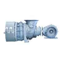
Advertisement

ABB Power2 850-M16 Operation Manual (106 pages)
High-pressure stage PT004087
Brand: ABB
|
Category: Industrial Equipment
|
Size: 14 MB
Table of Contents
-
-
Safety16
-
Introduction16
-
Intended Use18
-
Oil Supply35
-
Service Work48
-
Introduction68
-
General91
-
Spare Parts94
-
Table 5295
-
Table 5396
-
Table 5497
-
Table 5598
-
Table 5699
-
Figures
104

ABB Power2 850-M16 Operation Manual (178 pages)
Brand: ABB
|
Category: Industrial Equipment
|
Size: 25 MB
Table of Contents
-
Safety
11-
Introduction12
-
Intended Use14
-
-
Spare Parts87
-
Figures89
-
Tables91
-
-
-
-
Introduction103
-
-
6 Spare Parts
135
-
-
-
Introduction150
-
-
6 Spare Parts
173

ABB Power2 850-M16 Operation Instructions Manual (172 pages)
Brand: ABB
|
Category: Industrial Equipment
|
Size: 34 MB
Table of Contents
-
-
Introduction98
-
Spare Parts126
-
Tools131
-
Figures132
-
Tables133
-
-
Introduction142
-
Spare Parts165
-
Tools169
-
Figures170
-
Tables171
Advertisement