Sign In
Upload
Manuals
Brands
ABB Manuals
Industrial Equipment
Power2 650-M
ABB Power2 650-M Transformer protection Manuals
Manuals and User Guides for ABB Power2 650-M Transformer protection. We have
2
ABB Power2 650-M Transformer protection manuals available for free PDF download: Operation Manual
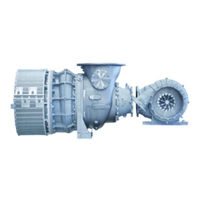
ABB Power2 650-M Operation Manual (119 pages)
Low-pressure stage
Brand:
ABB
| Category:
Industrial Equipment
| Size: 17 MB
Table of Contents
Table of Contents
1
Introduction
4
Purpose of the Manual
4
Contact Information
4
Essential Information
5
Power2 Layout and Function
7
Fig. 1: Power2 with Bellows Layout and Function
7
Layout and Function of the Low-Pressure Stage
8
Fig. 2: Layout and Function of the Low-Pressure Stage
8
Fig. 3: Function of the Low-Pressure Stage
9
Symbols, Definitions
10
Registered Trademarks
11
Table 1: Definition of Pictograms
11
Fig. 4: Volatile Corrosion Inhibitor (VCI)
12
Storage of New Low-Pressure and High-Pressure Stages
12
Fig. 5: Package with Hygrometer
13
Safety
14
Introduction
14
CE Conformity
14
Definition of Mandatory Signs
15
Definition of Safety Instructions
15
Table 2: Personal Protective Equipment to be Worn at All Times
15
Table 3: Personal Protective Equipment to be Worn Specific to the Respective Task
15
Intended Use
16
Deflagration on Gas Engines
17
Warning Plates on the Low-Pressure Stage
18
Fig. 6: Location of Power2 LP Warning Plates
18
Table 5: Recommended Replacement Intervals
19
Table 6: Further Data
19
Rating Plate of the Low-Pressure Stage
19
Table 4: Operating Limits
19
Fig. 7: Rating Plate
19
Periodic Check of the Pressure Vessels
20
Fig. 8: Location of Power2 LP Rating Plate
20
Lifting of Loads
21
Fig. 9: Attachment of Loads on the Crane Hook
21
Fig. 10: Attachment Angle
21
Prerequisites for Operation and Maintenance
22
Hazards During Operation and Maintenance
23
Safe Operation
25
Safe Maintenance
26
Table 8: Transporting the Low-Pressure Stage
30
Transport / Weight
30
Table 7: Swivel Lifting Eyes to be Used
30
Removal and Installation
30
Removing the Low-Pressure Stage
31
Fig. 11: Suspension of Complete Low-Pressure Stage
31
Installing the Low-Pressure Stage
32
Fig. 12: Suspension of Complete Low-Pressure Stage
32
Commissioning
33
Oil Supply
33
Table 9: Pre-Lubrication Time
33
Table 10: Post-Lubrication Time
33
Table 11: Filter Mesh Width
34
Inspection Procedures
35
Commissioning after Taking out of Operation
37
Monitoring During Operation
38
Lubricating Oil Pressure
38
Lubricating Oil Temperature
39
Table 12: Oil Pressure Range
39
Table 13: Lubricating Oil Temperature
39
Speed Measurement
40
Fig. 13: Functional Principle
40
Fig. 14: Dimension X
41
Fig. 15: Removing the Speed Measurement System
42
Fig. 16: Setting Dimension X
42
Fig. 17: Control Dimension S
43
Operation and Service
45
Noise Emission
45
Service Work
46
Expected Replacement Intervals
48
Table 14: Expected Replacement Intervals [H]
48
Stopping the Engine
49
Periodic Maintenance
50
Foreword to Maintenance
50
Table 15: Maintenance Intervals
50
Cleaning the Compressor During Operation
51
Table 16: Cleaning Parameters Power2 LP
53
Table 17: Cleaning Parameters Power2 HP
53
Cleaning Turbine and Nozzle Ring During Operation
54
Cleaning the Filter Silencer
54
Fig. 18: Cleaning the Filter Silencer
54
Table 19: Tightening Torque (81273)
56
Fig. 19: Cleaning the Filter Silencer (2)
56
Table 18: Tightening Torque (81272)
56
Fig. 20: Cleaning the Filter Silencer
57
Troubleshooting
59
Malfunctions When Starting
59
Table 20: Malfunctions When Starting - Delayed Start-Up
59
Table 21: Malfunctions When Starting - Vibrations
59
Table 22: Malfunctions When Starting - Rubbing of Rotating Parts
59
Malfunctions During Operation
60
Table 23: Malfunctions During Operation - Lubricating Oil Pressure too Low
60
Table 24: Malfunctions During Operation - Power2 LP Speed Reductions
60
Table 25: Malfunctions During Operation - Power2 HP Speed Reductions
60
Table 26: Malfunctions During Operation - Power2 LP Speed Increases
60
Table 27: Malfunctions During Operation - Power2 HP Speed Increases
61
Table 28: Malfunctions During Operation - Exhaust Gas Temperature too High
61
Table 29: Malfunctions During Operation - Charge Air Pressure too Low
62
Table 30: Malfunctions During Operation - Charge Air Pressure too High
62
Table 31: Malfunctions During Operation - Compressor 1 Contamination
63
Table 32: Malfunctions During Operation - Compressor 2 Contamination
63
Surging of the Low-Pressure or High-Pressure Stage
64
Table 33: Surging of the Low-Pressure or High-Pressure Stage
64
Malfunctions When Stopping
65
Speed Measurement System
65
Table 34: Malfunctions When Stopping - Runout Noises
65
Table 35: Malfunctions When Stopping - Runout Time too Short
65
Table 36: Measured Speed Incorrect
65
Disassembly and Assembly
66
Introduction
66
Material Required
67
Weights of Assemblies
68
Fig. 21: Overview of Assemblies
68
Table 37: Weights of the Assemblies
68
Removing the Filter Silencer and Injection Ring
69
Fig. 22: Removing the Filter Silencer and Injection Ring
69
Removing the Air Suction Branch and Injection Ring
70
Fig. 23: Removing Air Suction Branch and Injection Ring
70
Axial Clearance a Prior to Disassembly
71
Fig. 24: Measuring Axial Clearance a
71
Table 38: Axial Clearance a
71
Removing the Wall Insert
72
Fig. 25: Removing Wall Insert 1
72
Fig. 26: Removing Wall Insert 2
73
Fig. 27: Removing Wall Insert 3
73
Removing the Compressor Casing
74
Fig. 28: Removing the Compressor Casing 1
74
Fig. 29: Removing the Compressor Casing 2
74
Removing the Cartridge Group
75
Fig. 30: Moving out Cartridge Group 1
75
Fig. 31: Moving out Cartridge Group 2
76
Fig. 32: Putting down Cartridge Group Onto Cover
76
Removing Turbine Diffuser and Nozzle Ring
77
Fig. 33: Removing Turbine Diffuser and Nozzle Ring 1
77
Fig. 34: Removing Turbine Diffuser and Nozzle Ring 2
77
Fig. 36: Removing Turbine Diffuser and Nozzle Ring 4
78
Fig. 35: Removing Turbine Diffuser and Nozzle Ring 3
78
Installing Turbine Diffuser and Nozzle Ring
79
Fig. 37: Installing the Nozzle Ring and Turbine Dif
79
Table 39: Tightening Torque (56017)
79
Fig. 38: Installing the Nozzle Ring and Turbine Dif
80
Table 40: Tightening Torque (61056)
80
Installing the Cartridge Group
81
Fig. 39: Installing O-Rings
81
Fig. 40: Installing the Cartridge Group 1
81
Fig. 41: Inserting the Cartridge Group
82
Table 41: Tightening Torque (42087)
82
Fig. 42: Measuring Control Dimension X
83
Table 42: Control Dimension X
83
Table 43: Tightening Torque (61037 / 72021)
84
Fig. 43: Installing the Compressor Casing
84
Installing the Compressor Casing
84
Installing the Wall Insert
85
Fig. 44: Installing the Wall Insert 1
85
Table 44: Tightening Torque (77016)
85
Fig. 45: Installing the Wall Insert 2
86
Table 45: Tightening Torque (72002)
86
Axial Clearance a after Assembly
87
Fig. 46: Measuring Axial Clearance a
87
Table 46: Axial Clearance a
87
Installing the Air Suction Branch and Injection Ring
88
Fig. 47: Installing the Air Suction Branch
88
Table 47: Tightening Torque (72004)
88
Table 48: Tightening Torque (72004 / 77022)
89
Installing the Filter Silencer and Injection Ring
89
Fig. 48: Installing the Injection Ring and Filter Silencer
89
Table of Tightening Torques
90
Fig. 49: Overview of Tightening Torques
90
Table 49: Tightening Torques
90
Taking out of Operation at Short Notice
91
Possible Emergency Repairs
91
Fig. 50: Cover Plate / Gasket, Sleeves and Screws
92
Table 50: Cover Plate / Gasket
92
Fig. 51: Fitting the Cover Plate
93
Fig. 52: Installing the Casing
93
Table 51: Tightening Torque (42087)
93
Process for Taking out of Operation
94
Lubricating Oil
94
General
94
Taking out of Operation for a Long Period
94
Material and Disposal
95
REACH and Rohs Compliance Declaration for Products
95
Disposing of Low-Pressure and High-Pressure Stage Components
96
Spare Parts
97
Ordering Spare Parts
97
Table 52: Customer Spare Part Set (97070)
98
Spare Part - Illustrations
99
Table 53
99
Table 54
100
Table 55
101
Table 56
102
Table 57
103
Table 58
104
Table 59
105
Table 60
106
Table 61
107
Table 62
108
Table 63
109
Table 64
110
Tools
111
Table 65: Customer Tool Set 90000
111
Table 66: Expected Replacement Interval
112
Table 67: Maintenance Interval
112
Periodic Maintenance
112
Commissioning and Operating
112
Gas Piping (Option)
112
Removal and Installation
113
Fig. 53: Removing Gas Piping
113
Table 68: Weight
113
Fig. 54: Installing Gas Piping
114
Table 69: Tightening Torque (51011 / 51013 / 61072)
114
Storage and Disposal
115
Spare Parts
115
Table 70: Customer Spare Part Set (97150)
115
Fig. 55: Gas Piping with Part Numbers (GEJ920 / Power2 650)
116
Table 71: Gas Piping with Part Numbers
116
Figures
117
Tables
118
Advertisement
ABB Power2 650-M Operation Manual (106 pages)
High-pressure stage
Brand:
ABB
| Category:
Industrial Equipment
| Size: 11 MB
Table of Contents
Table of Contents
1
Contact Information
4
Introduction
4
Purpose of the Manual
4
Essential Information
5
Power2 Layout and Function
7
Fig. 1: Power2 with Bellows Layout and Function
7
Layout and Function of the High-Pressure Stage
8
Fig. 2: Layout of the High-Pressure Stage
8
Fig. 3: Function of the High-Pressure Stage
9
Symbols, Definitions
10
Table 1: Definition of Pictograms
11
Registered Trademarks
11
Storage of New Low-Pressure and High-Pressure Stages
12
Fig. 4: Volatile Corrosion Inhibitor (VCI)
12
Fig. 5: Package with Hygrometer
13
Safety
14
Introduction
14
CE Conformity
14
Table 3: Personal Protective Equipment to be Worn Specific to the Respective Task
15
Table 2: Personal Protective Equipment to be Worn at All Times
15
Definition of Safety Instructions
15
Definition of Mandatory Signs
15
Intended Use
16
Deflagration on Gas Engines
17
Warning Plates on the High-Pressure Stage
18
Fig. 6 High-Pressure Stage
18
Rating Plate of the High-Pressure Stage
19
Fig. 7: Rating Plate
19
Table 4: Operating Limits
19
Table 5: Recommended Inspection and Replacement Intervals
19
Table 6: Further Data
19
Periodic Check of the Pressure Vessels
20
Fig. 8: Location of Power2 HP Rating Plate
20
Lifting of Loads
21
Fig. 9: Attachment of Loads on the Crane Hook
21
Fig. 10: Attachment Angle
21
Prerequisites for Operation and Maintenance
22
Hazards During Operation and Maintenance
23
Safe Operation
25
Safe Maintenance
26
Table 8: Weight of Complete High-Pressure Stage
30
Table 7: Swivel Lifting Eyes
30
Transport / Weight
30
Fig. 12: Transport
30
Fig. 11: Swivel Lifting Eye (Example)
30
Removal and Installation
30
Removing the High-Pressure Stage
31
Fig. 13: Removing the High-Pressure Stage
31
Fig. 14: Loosening the Clamping Nut
32
Fig. 15: Removing the High-Pressure Stage
33
Installing the High-Pressure Stage
34
Fig. 16: Gaskets in the Slots of the Bearing Casing
34
Fig. 17: Preparing the Fastening Elements of the High-Pressure Stage
35
Fig. 18: Placing the High-Pressure Stage on the Bracket
36
Table 9: Values X and L
36
Fig. 19: Steps for Fastening the High-Pressure Stage
37
Fig. 20: Preparing the Clamping Nut for the Tightening Procedure
38
Fig. 21: Tightening Pressure Screws
39
Table 10
39
Commissioning
40
Oil Supply
40
Table 11: Pre-Lubrication Time
40
Table 12: Post-Lubrication Time
40
Table 13: Filter Mesh Width
41
Inspection Procedures
42
Commissioning after Taking out of Operation
44
Monitoring During Operation
45
Lubricating Oil Pressure
45
Lubricating Oil Temperature
46
Table 14: Oil Pressure Range
46
Table 15: Lubricating Oil Temperature
46
Speed Measurement
47
Fig. 22: Layout and Overview
47
Noise Emission
50
Operation and Service
50
Service Work
51
Expected Replacement Intervals
53
Table 16: Expected Replacement Intervals [H]
53
Stopping the Engine
54
Periodic Maintenance
55
Foreword to Maintenance
55
Table 17: Maintenance Intervals
55
Cleaning the Compressor During Operation
56
Table 19: Cleaning Parameters Power2 HP
58
Table 18: Cleaning Parameters Power2 LP
58
Cleaning Turbine and Nozzle Ring During Operation
58
Table 21: Malfunctions When Starting - Vibrations
59
Table 22: Malfunctions When Starting - Rubbing of Rotating Parts
59
Troubleshooting
59
Table 20: Malfunctions When Starting - Delayed Start-Up
59
Malfunctions When Starting
59
Table 25: Malfunctions During Operation - Power2 HP Speed Reductions
60
Table 26: Malfunctions During Operation - Power2 LP Speed Increases
60
Table 24: Malfunctions During Operation - Power2 LP Speed Reductions
60
Table 23: Malfunctions During Operation - Lubricating Oil Pressure too Low
60
Malfunctions During Operation
60
Table 27: Malfunctions During Operation - Power2 HP Speed Increases
61
Table 28: Malfunctions During Operation - Exhaust Gas Temperature too High
61
Table 29: Malfunctions During Operation - Charge Air Pressure too Low
62
Table 30: Malfunctions During Operation - Charge Air Pressure too High
62
Table 31: Malfunctions During Operation - Compressor 1 Contamination
63
Table 32: Malfunctions During Operation - Compressor 2 Contamination
63
Surging of the Low-Pressure or High-Pressure Stage
64
Table 33: Surging of the Low-Pressure or High-Pressure Stage
64
Table 35: Malfunctions When Stopping - Runout Time too Short
65
Table 36: Measured Speed Incorrect
65
Speed Measurement System
65
Table 34: Malfunctions When Stopping - Runout Noises
65
Malfunctions When Stopping
65
Disassembly and Assembly
66
Introduction
66
Material Required
67
Fig. 23: Swivel Lifting Eye (Example)
68
Table 37: Swivel Lifting Eyes
68
Table 38: Weights of the Assemblies
69
Fig. 24: Weights of the Assemblies
69
Weights of Assemblies
69
Removing the Compressor Casing
70
Fig. 25: Removing the Compressor Casing
70
Removing the Cartridge Group
71
Fig. 26: Removing the Cartridge Group
72
Fig. 27: Removing the Nozzle Ring
73
Installing the Cartridge Group
74
Fig. 28: Nozzle Ring Compression PD
74
Table 39: Nozzle Ring Compression PD
74
Fig. 29: Installing the Nozzle Ring
75
Table 40: Tightening Torque (51007)
76
Fig. 30: Installing the Cartridge Group
76
Installing the Compressor Casing
77
Fig. 31: Installing the Compressor Casing
77
Table 41: Tightening Torques (42007, 72011, 77022)
77
Measuring Radial Clearances N and R
78
Fig. 32: Measuring Clearances N and R
78
Table 42: Permissible Clearances N and R
78
Table 43: Permissible Clearances a and B
79
Fig. 33: Measuring Clearance a and B
79
Measuring Clearance a and B
79
Table of Tightening Torques
80
Fig. 34: Overview of Tightening Torques
80
Table 44: Tightening Torques [Nm]
80
Taking out of Operation at Short Notice
81
Possible Emergency Repairs
81
Installing a Replacement Cartridge Group
82
Fitting the Cover Plate
83
Fig. 35: Attaching a Cover Plate
83
Table 45: Tightening Torque (51007)
83
Table 46: Cover Plate Dimensions [MM]
84
Fig. 36: Cover Plate Drawing
84
Cover Plate Drawing
84
Fig. 37: Figure for Cover Plate, Slots for O-Rings
85
Table 47: Dimensions of Cover Plate, Slots for O-Rings [MM]
85
Taking out of Operation for a Long Period
86
General
86
Lubricating Oil
86
Process for Taking out of Operation
86
Material and Disposal
87
REACH and Rohs Compliance Declaration for Products
87
Disposing of Low-Pressure and High-Pressure Stage Components
88
Spare Parts
89
Ordering Spare Parts
89
Table 48: Customer Spare Part Set (97070)
90
Spare Part - Illustrations
91
Table 49
91
Table 50
92
Table 51
93
Table 52
94
Table 53
95
Table 54
96
Table 55
97
Tools
102
Figures
104
Advertisement
Related Products
ABB Power2 650-M46
ABB Power2 850-M16
ABB Power2 Series
ABB Power2 550-M
ABB Power2 850-M46
ABB Power2 340-H
ABB Power2 850 HP
ABB Power2 340-H44
ABB Power2 845-M46
ABB Power2 550-M44
ABB Categories
Industrial Equipment
Controller
Measuring Instruments
Battery Charger
DC Drives
More ABB Manuals
Login
Sign In
OR
Sign in with Facebook
Sign in with Google
Upload manual
Upload from disk
Upload from URL