Sign In
Upload
Manuals
Brands
ABB Manuals
DC Drives
ACS5000
ABB ACS5000 Manuals
Manuals and User Guides for ABB ACS5000. We have
3
ABB ACS5000 manuals available for free PDF download: User Manual
ABB ACS5000 User Manual (180 pages)
Water-cooled system drives
Brand:
ABB
| Category:
DC Drives
| Size: 15.18 MB
Table of Contents
Table of Contents
3
1 About this Manual
15
Equipment Covered by this Manual
15
Structure of the User Documentation
15
Related Documents
16
Table 1-1 Maintenance
16
Table 1-2 Technical Data
16
Table 1-3 Schematics
16
Table 1-4 Specifications and Guidelines
16
Table 1-5 Manuals
16
Table 1-6 I/O Interface
16
Terms and Abbreviations
17
Table 1-8 Terms and Abbreviations
17
Table 1-7 Serial Communications Interfaces
17
Target Groups and Required Qualification
19
Handling
19
Mechanical Installation
19
Electrical Installation
19
Operation
19
Maintenance
20
User's Responsibilities
20
Intended Use of Equipment
20
Quality Certificates and Applicable Standards
21
Table 1-9 Standards that Are Referred to in this Document
21
Items Covered by Delivery
22
Identifying the Delivery
22
Tools
22
Figure 1-1 Typical Delivery
22
2 Important Safety Information
23
Safety Standards
23
Safety Messages
23
Product Safety Labels
24
Figure 2-1 Product Warning Label Examples (Label Placement Depends on the Drive)
24
General Safety Instructions
25
The 7 Steps that Save Lives
26
Possible Residual Risks
28
Important Note - Main Circuit Breaker
29
Figure 2-2 Drive System Overview
29
Maintenance Recommendation
30
Safety and Protection Requirements
30
3 Power Electronics and Cabinet Features
31
Main Features of the Drive
31
Figure 3-1 Typical Block Diagram of the Drive
31
Figure 3-2 Switching Levels
32
Figure 3-3 Principle of 9-Level Topology
32
Figure 3-4 IGCT
33
Frame Sizes
34
Figure 3-5 Frame Sizes 1 - 4
34
Table 3-1 Line-Up Specifications by Frame Size
34
Phase Converter Unit (PCU)
35
Primary Phase Converter Unit (1700 MM and 2100 MM)
36
Figure 3-6 Primary PCU, 1700 MM
36
Figure 3-7 Primary PCU, 1700 MM: Side View Left (A) and Side View Right (B)
37
Figure 3-8 Primary PCU, 2100 MM
38
Figure 3-9 Primary PCU, 2100 MM: Side View Left (A) and Side View Right (B)
39
Secondary Phase Converter Unit (1700 MM and 2100 MM)
40
Figure 3-10 Secondary PCU, 1700 MM (A) and 2100 MM (B)
40
Control Unit (COU)
41
Figure 3-11 Block Diagram of Control System
41
Main Components
42
Figure 3-12 COU Control Section
42
AMC Circuit Board
43
Figure 3-13 DTC Torque Control
44
Figure 3-14 Local Control Panel
46
Figure 3-15 COU Customer Interface Section
47
Transformer and Motor Cable Terminals
48
Transformer Cable Terminals
48
Motor Cable Terminals
48
Figure 3-16 Motor Terminal Section of Frame Size 1 and 2: Top Entry (A) and Bottom Entry (B)
48
Figure 3-17 Motor Terminal Section of Frame Size 3 and 4: Top Entry (A) and Bottom Entry (B)
49
Water Cooling Unit (WCU)
50
Figure 3-18 WCU (1400 MM), Frame Size 3
50
EXU - Excitation Unit (Optional)
51
Figure 3-19 EXU
51
Figure 3-20 EXU Control Panel
52
Door Interlocking System
53
Figure 3-21 Location of Protection Features and Lights
53
Grounding Switches
54
Locking Bars
54
Figure 3-22 Grounding Switch
54
Figure 3-23 Locking Bar and White Lamp
55
Grounding Studs
56
Grounding Set
56
Figure 3-24 Grounding Stud
56
Figure 3-25 4-Way Grounding Set
56
Output Grounding Studs in COU
57
Figure 3-26 Connection Studs for the 4-Way Grounding Set in the COU
57
Input Grounding Studs in a PCU
58
Figure 3-27 Connection Studs for the 4-Way Grounding Set in an 18-Pulse ACS5000WPCU (A) and a 36-Pulse ACS5000W PCU (B)
58
4 Transportation, Storage and Disposal
59
Safety
59
Transport Conditions
59
Unpacking and Inspection
59
Identifying Drive Units
59
Packing List
60
Packing Label
60
Lifting and Transportation
61
Using a Crane to Lift a Transport Unit or the Drive by the Base Frame
62
Figure 4-1 Lifting Bracket on Base Frame of a Drive and Safety Hook
62
Figure 4-2 Lift Frame and Lift Spreader
63
Storage
64
Storage Conditions
64
Storage and Handling of Spare Parts
65
Warranty Information
65
Disposal of Packaging Materials and Components
66
5 Mechanical Installation
67
Safety
67
Overview of Installation Work
67
General Notes on Installation
68
Dimensions and Clearances
68
Rear and Top Access to the Cabinet
68
Cabinet Roof
68
Fire Protection
68
Cable Duct Material
68
Installation Material
68
Tools
68
Preparing the Installation Site
69
Figure 5-1 Floor Inclination
69
Aligning Transport Units
70
Joining Transport Units
71
Figure 5-2 Connection Points on Side of Transport Units (PCU Example)
71
Applying Silicone
72
Installing Roof Joints
72
Figure 5-3 Applying Silicone
72
Figure 5-4 Roof Joint
72
Table 5-1 Installation Material Per Roof Joint
72
Installing Roof-Mounted Cooling Units
73
Lifting a Unit with a Crane
73
Figure 5-5 Lifting a Cooling Unit (Example with IP54 Unit)
73
Installing IP42 Roof-Mounted Cooling Units
74
Table 5-2 Installation Material Per IP42 Unit
74
Figure 5-6 Cable Duct Openings (Example with 1700 MM PCU)
75
Installing IP54 Roof-Mounted Cooling Units
76
Table 5-3 Installation Material Per IP54 Unit
76
Figure 5-7 Water Inlet / Outlet and Drain Outlet (Back View)
77
Installing Roof Attachments
78
Figure 5-8 Roof Attachment
78
Figure 5-9 Recommended Ceiling and Wall Fixings
79
Joining Water Pipes
80
Removing a Pipe Joint
80
Joining Busbars
81
Figure 5-10 Busbar Connections
81
Figure 5-11 AC Busbar Connection
82
Figure 5-12 PE Ground Busbar Connection
82
Figure 5-13 DC Busbar Connection
82
Connecting the Heating Cable
83
Figure 5-14 Heating Cable Connection
83
Connecting Raw Water Pipes
84
Fixing the Drive to the Floor
84
6 Electrical Installation
85
Safety
85
Overview
85
Cable Requirements
85
Power Cables
85
Auxiliary and Control Cables
85
Grounding
86
Grounding the Transformer and an 18-Pulse Drive
86
Figure 6-1 Grounding the Transformer and an 18-Pulse Drive (in PCU)
86
Grounding the Transformer and a 36-Pulse Drive
87
Figure 6-2 Grounding the Transformer and a 36-Pulse Drive (in PCU)
87
Grounding the Drive and the Motor (Multi-Point Bonding)
88
Figure 6-3 Grounding the Drive and the Motor (Multi-Point Bonding)
88
Grounding the Drive and the Motor (Single-Point Bonding)
89
Figure 6-4 Grounding the Drive and the Motor (Single-Point Bonding)
89
Ground Cable Connection
90
Figure 6-5 PE Ground Busbar in a COU
90
Figure 6-6 PE Ground Busbar in a PCU Frame Size 1 (A) and Frame Size
90
Internal Wiring
91
Optical Fibers
92
Figure 6-7 Wiring Across Shipping Splits, Frame Size 1 (A) and 2 (B)
93
Figure 6-8 Wiring Across Shipping Splits, Frame Size 3 and 4
94
Cable Entries
95
Cable Entry with Sealing Modules, Type 1
95
Figure 6-9 Cable Entry with Sealing Modules - Type 1
95
Figure 6-10 Cable Entry Frame Sizes (Top) for Type 1 Sealing Modules (Bottom)
96
Table 6-1 Type 1 Sealing Modules and Cables Per Frame Opening
96
Table 6-2 Maximum Number of Type 1 Sealing Modules Per Frame Opening
96
Table 6-3 Maximum Number of Cables Per Frame Opening - 3 Core
96
Table 6-4 Maximum Number of Cables Per Frame Opening - Single Core
96
Cable Entry with Sealing Modules, Type 2
97
Cable Entry with Cable Glands
97
Figure 6-11 Cable Entry with Sealing Modules - Type 1
97
Figure 6-12 Cable Entry with Cable Gland
97
Cable Entry with EMC Plates
98
Figure 6-13 Cable Entry with EMC Plates
98
Power Cables, Ground Cables, Equipotential Bonding Conductor
99
Preparing the Cable Entry and the Cables
99
Determining the Cable Length
99
Preparing Cables for Cable Entries with Cable Glands
100
Figure 6-14 Preparing Power Cables for Cable Glands
100
Preparing Cables for Cable Entries with Sealing Modules
101
Figure 6-15 Preparing Power Cables for Sealing Modules
101
Connecting the Cables
102
Checking the Cable Insulation
102
Figure 6-16 PCU 36-Pulse Top and Bottom Entry (Back View)
103
Figure 6-17 PCU 18-Pulse Top and Bottom Entry (Back View)
103
Figure 6-18 COU Cable Terminals, Top and Bottom Entry (Back View)
104
Bolted Connections
105
Figure 6-19 Bolted Busbar Connection
105
Auxiliary Power Cables and Control Cables
106
Preparing the Cable Entry and the Cables
106
Figure 6-20 Preparing Control Cables for EMC Plates
107
Figure 6-21 Preparing Control Cables for Sealing Modules
108
Preparing Cables for Cable Entries with Sealing Modules
108
Preparing Cables for Cable Entries with Cable Glands
109
Connecting the Cables
109
Figure 6-22 Preparing Control Cables for Cable Glands
109
Connecting Auxiliary Power Cables and Space Heater Cables in WCU
110
Figure 6-23 Cable Routing in WCU800 (A) and WCU1400 (B) Cabinets
110
Connecting Cables in COU
111
Figure 6-24 Shield Grounding Clamp
111
Figure 6-25 COU Customer Interface Section
111
7 Commissioning
113
Required Qualification
113
Commissioning Procedure
113
Commissioning Checklist
113
Customer Assistance
113
Customer Acceptance
113
Commissioning Checklists
114
Mechanical Installation Checklist
114
Electrical Installation Checklist
114
Door Interlocking Checklist
115
Main Circuit Breaker (MCB)
115
Input Transformer Checklist
115
Motor Checklist
116
Insulation Tests Checklist
116
Power Checklist
116
Miscellaneous Checklist
116
8 Operation
117
Operating Conditions
117
Safety
117
Overview
117
Local Operator Panel
118
Figure 8-1 Local Operator Panel
118
Lamp-Test Function
119
Status Messages
119
Start Sequence of the Drive
121
Stop Sequence of the Drive
122
Emergency-Off Sequence
122
Starting the Drive
123
Checks before Starting the Drive
124
Starting the Drive from Remote
124
Starting the Drive Locally
124
Stopping the Drive
127
Emergency-Off
128
Initiating an Emergency off
128
Starting the Drive System after an Emergency-Off
129
Arc Resistant Design
130
Internal Arc Classification (IAC)
130
Figure 8-2 IAC Label Example
130
Table 8-1 ABB Arc Resistant Classes
130
Arc Detection with the Arc Guard System
131
Action after the Arc Guard System™ Has Been Triggered
131
Figure 8-3 Arc Guard™ System with HMI Panel
131
Figure 8-4 HMI Panel
131
Energizing and Grounding the Drive
132
Opening the Doors
132
9 CDP Control Panel
133
Overview
133
Display and Keypad
133
Figure 9-1 CDP Control Panel
133
Functions
134
Modes
134
Identification Mode
134
Actual Signals Mode
136
Overview
136
Figure 9-2 Control Panel Functions for Actual Signals Mode
136
Selecting the Actual Signals Display
137
Toggling between Actual Signals Display and Fault Memory
138
Displaying Three Actual Signals
138
Selecting Actual Signals
138
Displaying a Fault and Resetting the Fault Memory
141
Displaying and Resetting an Active Fault
142
Parameters Mode
143
Figure 9-3 Control Panel Functions for Parameters Mode
143
Overview
144
Changing a Parameter Setting
145
User Lock
147
Functions Mode
148
Adjusting the Display Contrast
148
Figure 9-4 Control Panel Functions for Functions Mode
148
Local and Remote Control Mode
150
Local Control
150
Disabling / Enabling Local Lock Function
150
Enabling the Local Lock
151
Remote Control
151
Operational Commands
152
Setting the Direction of Rotation
152
Entering a Reference Value
153
10 Preventive and Corrective Maintenance
155
General Information
155
Required Qualification
155
Maintenance Schedule
155
Logbook
155
Spare Parts
155
Identifying Electrical Equipment
156
Device Designation
156
Cables and Wires
156
Understanding Wiring Diagrams
156
Figure 10-1 Device Identification
156
Figure 10-2 Cable and Wire Designation
156
Alarm / Fault Indications
157
Messages
157
Error Message Levels
157
Alarm
157
Fault
158
Alarm / Fault Messages
158
Fault Handling
158
Standard Troubleshooting Procedure
159
Removing the CDP Control Panel
160
Leds and Switches on Circuit Boards and I/O Devices
161
AMC Circuit Board
161
Figure 10-3 Leds of AMC Circuit Board
161
S800 I/O Bus Modem TB820
162
Bus Modem Address
162
Figure 10-4 TB820 Bus Modem
162
S800 I/O Modules
163
Figure 10-5 Example of S800 I/O Station
163
Corrective Maintenance
164
Safety
164
Energizing the Drive
165
Stopping the Motor
165
Energizing the Drive
166
Opening and Closing the Doors
167
Grounding Switch Is Not Released
169
Emergency Release of a Door Safety Switch
170
Location of Safety Switches
170
Figure 10-6 Location of Safety Switches
170
Safety-Switch Settings
171
Figure 10-7 Safety Switch
171
Visual Checks on the Drive
173
Cleaning
173
Cleaning the Drive Cabinet
173
Checking Wire and Cable Connections
174
Checking and Replacing Filter Mats
174
Location
174
Replacing Filter Mats
174
Table 10-1 Filter Mat Specifications
174
Replacing a Door-Mounted Fan
175
Figure 10-8 Filter Mat Replacement for PCU (A) and WCU (B)
175
Replacing a Fan of an IP42 Roof-Mounted Cooling Unit
176
Replacing a Fan
176
Figure 10-9 Roof-Mounted Cooling Unit (IP42)
176
Replacing a Fan of an IP54 Roof-Mounted Cooling Unit
177
Replacing a Fan
177
Figure 10-10 Roof-Mounted Cooling Unit (IP54)
177
Advertisement
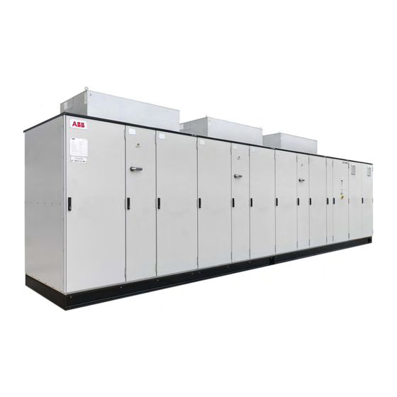
ABB ACS5000 User Manual (186 pages)
Water-cooled
Brand:
ABB
| Category:
DC Drives
| Size: 4.57 MB
Table of Contents
Cable Entry with Sealing Modules, Type
2
Table of Contents
3
About this Manual
19
Equipment Covered by this Manual
19
Structure of the User Documentation
19
Related Documents
20
Terms and Abbreviations
21
Trademarks
23
Electrical Installation
24
Handling
24
Mechanical Installation
24
Operation
24
Target Groups and Required Qualification
24
Maintenance
25
User's Responsibilities
25
Intended Use of Equipment
25
Cyber Security Disclaimer
25
Quality Certificates and Applicable Standards
27
Identifying the Delivery
28
Items Covered by Delivery
28
Tools
28
Important Safety Information
29
Safety Messages
29
Safety Standards
29
Product Safety Labels
30
General Safety Instructions
31
The 7 Steps that Save Lives
32
Possible Residual Risks
34
Important Note - Main Circuit Breaker
35
Maintenance Recommendation
36
Power Electronics and Cabinet Features
37
Safety and Protection Requirements
36
Main Features of the Drive
37
Frame Sizes
40
Phase Converter Unit (PCU)
41
Primary Phase Converter Unit (1700 MM and 2100 MM)
41
Secondary Phase Converter Unit (1700 MM and 2100 MM)
46
Control Unit (COU)
47
Main Components
48
AMC Circuit Board
49
Transformer and Motor Cable Terminals
54
Motor Cable Terminals
54
Water Cooling Unit (WCU)
56
EXU - Excitation Unit (Optional)
57
Door Interlocking System
59
Grounding Switches
60
Transformer Cable Terminals
54
Locking Bars
61
Grounding Set
62
Grounding Studs
62
Output Grounding Studs in COU
63
Input Grounding Studs in a PCU
64
Transportation, Storage and Disposal
65
Safety
65
Transport Conditions
65
Unpacking and Inspection
65
Identifying Drive Units
66
Packing List
66
Packing Label
67
Lifting and Transportation
67
Using a Crane to Lift a Transport Unit or the Drive by the Base Frame
68
Storage
70
Storage Conditions
70
Storage and Handling of Spare Parts
71
Warranty Information
71
Disposal of Packaging Materials and Components
72
Mechanical Installation
73
Overview on Installation Work
73
Safety
73
Cabinet Roof
74
Cable Duct Material
74
Dimensions and Clearances
74
Fire Protection
74
General Notes on Installation
74
Installation Material
74
Rear and Top Access to the Cabinet
74
Tools
74
Preparing the Installation Site
75
Aligning Transport Units
75
Joining Transport Units
77
Applying Silicone
78
Installing Roof Joints
78
Installing Roof-Mounted Cooling Units" on Page 79 (Option)
79
Lifting a Unit with a Crane
79
Installing IP42 Roof-Mounted Cooling Units
80
Installing IP54 Roof-Mounted Cooling Units
82
Installing Roof Attachments" on Page 84 (Option)
84
Joining Water Pipes
86
Removing a Pipe Joint
86
Joining Busbars
87
Connecting the Heating Cable" on Page 89 (Option)
89
Connecting Raw Water Pipes
90
Fixing the Drive to the Floor
90
Electrical Installation
91
Overview
91
Safety
91
Auxiliary and Control Cables
92
Grounding
93
Cable Requirements
92
Power Cables
92
Grounding the Transformer and the Drive
93
Grounding the Drive and the Motor (Multi-Point Bonding)
94
Grounding the Drive and the Motor (Single-Point Bonding)
95
Ground Cable Connection
96
Internal Wiring
97
Optical Fibers
98
Cable Entries
101
Cable Entry with Cable Glands
103
Cable Entry with Sealing Modules, Type
103
Cable Entry with EMC Plates
104
Power Cables, Ground Cables, Equipotential Bonding Conductor
105
Determining the Cable Length
105
Preparing the Cable Entry and the Cables
105
Preparing Cables for Cable Entries with Cable Glands
106
Preparing Cables for Cable Entries with Sealing Modules
107
Checking the Cable Insulation
108
Connecting the Cables
108
Connecting the Cables
109
Bolted Connections
111
Auxiliary Power Cables and Control Cables
112
Preparing the Cable Entry and the Cables
112
Preparing Cables for Cable Entries with Sealing Modules
114
Connecting the Cables
115
Preparing Cables for Cable Entries with Cable Glands
115
Connecting Auxiliary Power Cables and Space Heater Cables in WCU
116
Connecting Cables in COU
117
Commissioning
119
Commissioning Checklist
119
Commissioning Procedure
119
Customer Acceptance
119
Customer Assistance
119
Required Qualification
119
Commissioning Checklists
120
Electrical Installation Checklist
120
Mechanical Installation Checklist
120
Door Interlocking Checklist
121
Input Transformer Checklist
121
Main Circuit Breaker (MCB)
121
Insulation Tests Checklist
122
Miscellaneous Checklist
122
Operation
123
Motor Checklist
122
Power Checklist
122
Local Operator Panel
123
Operating Conditions
123
Overview
123
Safety
123
Lamp-Test Function
125
Status Messages
125
Start Sequence of the Drive
127
Stop Sequence of the Drive
128
Emergency-Off Sequence
129
Starting the Drive
129
Checks before Starting the Drive
130
Starting the Drive from Remote
130
Starting the Drive Locally
130
Stopping the Drive
133
Emergency-Off
134
Initiating an Emergency off
134
Starting the Drive System after an Emergency-Off
134
Arc Resistant Design
136
Internal Arc Classification (IAC)
136
Action after the Arc Guard System™ Has Been Triggered
137
Arc Detection with the Arc Guard System
137
Energizing and Grounding the Drive
138
Opening the Doors
138
CDP Control Panel
139
Display and Keypad
139
Overview
139
Functions
140
Modes
140
Identification Mode
140
Actual Signals Mode
142
Overview
142
Selecting the Actual Signals Display
143
Displaying Three Actual Signals
144
Selecting Actual Signals
144
Toggling between Actual Signals Display and Fault Memory
144
Displaying a Fault and Resetting the Fault Memory
146
Displaying and Resetting an Active Fault
148
Parameters Mode
149
Overview
150
Changing a Parameter Setting
151
Enabling / Unlocking a Parameter Lock
153
User Lock
153
Adjusting the Display Contrast
154
Functions Mode
154
Disabling / Enabling Local Lock Function
156
Local and Remote Control Mode
156
Local Control
156
Enabling the Local Lock
157
Remote Control
157
Operational Commands
158
Setting the Direction of Rotation
158
Entering a Reference Value
159
Device Designation
161
General Information
161
Identifying Electrical Equipment
161
Logbook
161
Maintenance Schedule
161
Preventive and Corrective Maintenance
161
Required Qualification
161
Spare Parts
161
Cables and Wires
162
Understanding Wiring Diagrams
162
10.3.2.1 Alarm
163
Alarm / Fault Indications
163
Error Message Levels
163
Fault
163
Messages
163
10.3.2.3 Alarm / Fault Messages
164
Fault Handling
164
Removing the CDP Control Panel
165
Standard Troubleshooting Procedure
165
Leds and Switches on Circuit Boards and I/O Devices
166
AMC Circuit Board
167
10.5.2.1 Bus Modem Address
168
S800 I/O Bus Modem TB820
168
Corrective Maintenance
169
S800 I/O Modules
169
Safety
171
10.6.2.1 Stopping the Motor
172
Energizing the Drive
172
Opening and Closing the Doors
174
Grounding Switch Is Not Released
176
10.6.5.1 Location of Safety Switches
177
Emergency Release of a Door Safety Switch
177
10.6.5.2 Safety-Switch Settings
178
Visual Checks on the Drive
179
Cleaning
180
Cleaning the Drive Cabinet
180
10.6.9.1 Location
181
10.6.9.2 Replacing Filter Mats
181
Checking and Replacing Filter Mats
181
Checking Wire and Cable Connections
181
Replacing a Door-Mounted Fan
182
10.6.11 Replacing a Fan of an IP42 Roof-Mounted Cooling Unit
183
10.6.11.1 Replacing a Fan
183
10.6.12 Replacing a Fan of an IP54 Roof-Mounted Cooling Unit
184
10.6.12.1 Replacing a Fan
184
ABB ACS5000 User Manual (178 pages)
Medium voltage AC drive air-cooled, 2 - 7 MVA
Brand:
ABB
| Category:
Air Conditioner
| Size: 18.71 MB
Table of Contents
Table of Contents
3
Contact Information
13
Copyright Notice
13
Document Identification
13
Equipment Covered by the Manual
13
General Information on Manual and Equipment
13
Structure of the User Documentation
14
Target Groups and Required Qualifications
15
Cyber Security Disclaimer
16
Intended Use of Equipment
16
Quality Certificates and Applicable Standards
16
Responsibilities of the User
16
Fig. 1 Delivered Items
17
Items Covered by Delivery
17
Identifying the Delivery
18
Identifying Transport Units
18
Meaning of Icons
20
Text Conventions
20
Writing Conventions
20
Important Note on Main Circuit Breaker
21
Minimum Requirements for MCB and MCB Control
22
Safety and Protection Requirements
22
Maintenance Recommendation
23
Chapter 1 - Safety
25
Meaning of Safety Instructions
25
General Safety Information
26
Possible Residual Risks
27
Safety Labels and Signs
28
Safety Labels
28
Fig. 1-1 Safety Labels
28
Safety Signs
29
Chapter 2 - Power Electronics and Cabinet Features
31
Overview
31
Power Supply Configurations
32
Main Power Supply with Input Transformer Configurations
32
Fig. 2-1 Drive Overview
32
Auxiliary Power Supply Configurations
33
Drive Topology
34
Fig. 2-2 Overview
34
Front End
35
DC Link
35
Fig. 2-3 DC Link
35
Fig. 2-4 Grounding Switch
36
Fig. 2-5 Grounding the Drive
37
INU - Inverter Unit
38
Terminal Compartment
39
Cable Entry
39
Fig. 2-6 Terminal Compartment
39
Input Transformer
40
Installation Solutions
40
Control Equipment
41
Cabinet Design
42
Fig. 2-7 Control Compartment of the Transformer
42
Door Locking System
43
Fig. 2-8 Door Locks
43
Cooling System
44
Configurations
44
Function
45
Fig. 2-9 Air Flow through the Drive
45
Fig. 2-10 Location of Air Pressure Switch in the Drive
46
Fig. 2-11 Location of Air Pressure Switch in the Transformer
46
Chapter 3 - Control System
47
Overview
47
Fig. 3-1 Block Diagram of Control System
47
Main Components
48
Fig. 3-2 Control Compartment
48
Local Control Panel
49
AMC Circuit Board
49
Fig. 3-3 Location of AMC Circuit Board
49
Fig. 3-4 DTC Torque Control
51
I/O Modules
52
S800 I/O System
52
Fig. 3-5 S800 I/O Stations
55
Fieldbus Communication Interfaces (Option)
57
Pulse Encoder Interface NTAC (Option)
60
Chapter 4 - Transportation, Storage and Disposal
61
Safety
61
Transport Conditions
61
Unpacking and Inspection
62
Lifting and Transportation
62
General Notes on Transportation
62
Using a Crane
63
Storage
64
Storage Conditions
64
Storage and Handling of Spare Parts
65
Storage Place Conditions
65
Handling Precautions
65
Disposal of Packaging Materials and Components
65
Chapter 5 - Mechanical Installation
67
Safety
67
Overview on Installation Work
67
General Notes on Installation
67
Dimensions, Clearances
67
Cabinet Roof
67
Fire Protection
67
Cable Duct Material
68
Preparing the Floor
68
Fixing the Cabinet to the Floor
68
Installing the Cabinet
69
Installing the Fan Units
70
Chapter 6 - Electrical Installation
71
Safety
71
Overview of Installation Work
71
Cables Requirements
71
Ground Cable Connection and Cable Shield Connections
72
Fig. 6-1 Grounding the Drive System
72
Cabling between Drive and Transformer
73
Drive with Integrated Transformer
73
Fig. 6-2 Drive with Integrated Transformer
73
Drive with Non-Integrated Transformer
74
Fig. 6-3 Drive with Non-Integrated Transformer
74
Cable Entries
75
Cable Entry with Sealing Modules, Type 1
75
Cable Entry with Cable Glands
76
Cable Entry with EMC Plates
76
Power Cables, Ground Cables, Equipotential Bonding Conductor
77
Further Information
77
Preparing the Cable Entries and the Cables
77
Fig. 6-4 Preparing Power Cables for Sealing Modules
78
Fig. 6-5 Preparing Power Cables for EMC Plates
80
Fig. 6-6 Preparing Power Cables for Cable Glands
81
Connecting the Cables
82
Fig. 6-8 Cable Connection and Bolt Orientation
83
Fig. 6-9 Cable Connection and Bolt Orientation
83
Auxiliary Power, Control and Serial Communication Cables
86
Further Information
86
Cable Entry
86
Fig. 6-13 Cable Entry for Auxiliary and Control Cables
86
Routing the Cables
87
Determining the Cable Length
87
Preparing the Cable Entry
87
Fig. 6-14 Routing Control Cables
87
Connecting the Cables
88
Final Checks
90
Power Supply Cables for Fan Units
90
Transformer Heating Cable
91
Fig. 6-19 Heating Cable Connection
91
Chapter 7 - Commissioning
93
Required Qualification
93
Commissioning Procedure
93
Commissioning Check List
93
Customer Assistance
93
Customer Acceptance
93
Commissioning Check List
95
Mechanical Installation
95
Electrical Installation
95
Main Circuit Breaker (MCB)
96
Input Transformer (if Applicable)
96
Motor
96
Insulation Tests
97
Power Supply
97
Miscellaneous
97
Chapter 8 - Operation
100
Safety
100
Overview
100
Overview of Local Operator Panel
100
Lamp Test
101
Fig. 8-1 Local Operator Panel
101
Status Messages
102
Overview on Status Messages
102
Start Sequence of the Drive
103
Stop Sequence of the Drive
104
Emergency-Off Sequence of the Drive
105
Starting the Drive
105
Checks before Starting the Drive
106
Starting the Drive from Remote
106
Starting the Drive Locally
107
Stopping the Drive
110
Emergency-Off
111
Function
111
Initiating an Emergency-Off
111
Starting the Drive after an Emergency-Off
112
Chapter 9 - CDP Control Panel
113
Overview
113
Display and Keypad
113
Fig. 9-1 CDP Control Panel
113
CDP Control Panel Functions
114
CDP Control Panel Modes
114
Identification Mode
115
Actual Signals Mode
116
Overview
116
Selecting the Actual Signals Display
118
Toggle between Actual Signals Display and Fault History
118
Displaying Three Actual Signals
118
Selecting Actual Signals
119
Displaying a Fault and Resetting the Fault History
121
Displaying and Resetting an Active Fault
123
Parameters Mode
123
Overview
123
Selecting and Changing Parameters
125
Enabling / Unlocking a Parameter Lock
128
Functions Mode
128
Overview
128
Adjusting the Display Contrast
129
Local and Remote Control
131
Local Control
131
Remote Control
132
Disabling / Enabling Local Lock Function
133
Operational Commands
134
Setting the Direction of Rotation
134
Entering a Reference Value
135
Chapter 10 - Preventive and Corrective Maintenance
137
General Information
137
Required Qualification
137
Maintenance Schedule
137
Logbook
137
Spare Parts
137
Identifying Electrical Equipment
138
Device Identification
138
Cables and Wires
138
Understanding Wiring Diagrams
138
Alarm / Fault Indications
139
Messages
139
Error Message Levels
141
Fault Handling
141
Troubleshooting Procedure
142
Removing the CDP Control Panel
143
Leds and Switches on Circuit Boards and I/O Modules
145
AMC Circuit Board
145
Fig. 10-2 AMC Circuit Board
145
S800 I/O - TB820 Bus Modem
146
S800 I/O Modules
147
Serial Communication Interfaces
148
Corrective Maintenance
155
Overview on Maintenance Tasks
155
Safety
155
De-Energizing the Drive Locally
156
Grounding Switches Are Not Released
158
Connecting a Grounding Set
160
Emergency Release of the Door Safety Switch
161
Door Handles
164
Visual Checks on the Drive
164
Cleaning
165
10.6.10 Checking Wire and Cable Connections
166
10.6.11 Replacing the Filter Mats
167
10.6.12 Replacing a Fan
169
Terms, Trademarks, Related Documentation
173
Terms and Abbreviations
173
Trademarks
175
Related Documentation
176
Advertisement
Advertisement
Related Products
ABB ACS580-0P-06A6-2
ABB ACS580-0P-031A-2
ABB ACS580-0P-059A-2
ABB ACS580-0P-04A8-4
ABB ACS580-0P-014A-4
ABB ACS580-0P-023A-4
ABB ACS580-0P-044A-4
ABB ACS580-0P-022A-6
ABB ACS580-0P
ABB ACS580-0P 3R Series
ABB Categories
Industrial Equipment
Controller
Measuring Instruments
Battery Charger
DC Drives
More ABB Manuals
Login
Sign In
OR
Sign in with Facebook
Sign in with Google
Upload manual
Upload from disk
Upload from URL