Advertisement
Quick Links
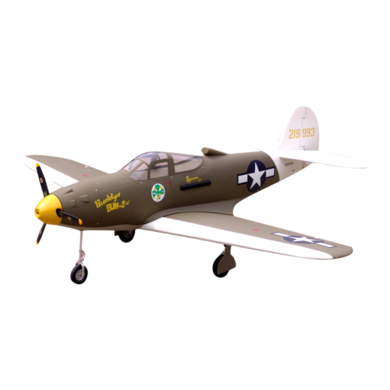
P-39 Airacobra
Specification:
Length:
1788mm(70.4")
Wing span:
2040mm(80.3")
Wing area:
78.5sq.dm(8.5sq.ft)
Wing loading: 93g/sq.dm(30.5oz/sq.ft)
Flying weight: 7.3kg(16.1bs)
Radio:
6ch & 8servos
Engine:
30cc gasoline engine
SAFETY PRECAUTIONS
INSTRUCTION MANUAL
This R/C airplane is not a toy!
(The people under 18 years old is forbidden from flying this model)
First-time builders should seek advice from people having building
experience.If misused or abused,it can cause serious bodily injury
and damage to property.
Fly only in open areas and preferably at a dedicated R/C flying site.
We suggest having a qualified instructor carefully inspect your
airplane before its first flight.Please carefully read and follow all
instructions included with this airplane,your radio control system
and any other components purchased separately.
Advertisement

Related Manuals for Troy Built Models P-39 Airacobra


Summary of Contents for Troy Built Models P-39 Airacobra
- Page 1 P-39 Airacobra Specification: Length: 1788mm(70.4") Wing span: 2040mm(80.3") Wing area: 78.5sq.dm(8.5sq.ft) Wing loading: 93g/sq.dm(30.5oz/sq.ft) Flying weight: 7.3kg(16.1bs) INSTRUCTION MANUAL Radio: 6ch & 8servos Engine: 30cc gasoline engine This R/C airplane is not a toy! (The people under 18 years old is forbidden from flying this model) First-time builders should seek advice from people having building experience.If misused or abused,it can cause serious bodily injury...
- Page 2 6 channel radio for aiplane is highly recommended for this model. 4-cycle .180 Optional parts: rubber wheel with metal hub. Spinner 18″X10 We strongly recommen you use the thread lock for all the screws when you build your model.
- Page 3 Assemble the aileron to main wing with instant type AB glue. Be careful Accessory list for the coming installation steps. to ensure the moving parts of the hinges are able to move freely. Three wheel retract system Clevis Retainer Rod (2x300mm) TP Screw (2.3x12mm) Make sure to assemble retracts as instructed below.
-
Page 4: Accessory List For The Coming Installation Steps
Secure the servo.Install the nylon control horn Keep some space about 1mm width between The centre of the Gravity. and connect the linkage. trailing edge and flap. TP Screw (2.3x12mm) TP Screw (2.3x12mm) Trailing edge 1.5mm Flap Rod (2x300mm) Screw (2x10mm) Lock Nut (3mm ) Washer(3x15mm) 150mm... - Page 5 Install the nylon control horn and connect the linkage. Mount the gear door and the wheel to the retract. Epoxy the landing gear to the wing steadily. Adjustment. Wheel (100mm) Retainer Bushing (8X4mm) Rod (2x300mm) Side View inside LockNut(4mm) Clevis RUDDER Screw (2x10mm) 40mm...
- Page 6 According to the rib template drill holes in one wing and Epoxy the exhaust to appropriate position in the Epoxy plies to relevant position inside the fuselage as Epoxy the wheel house to the wings carefully. epoxy wood dowel in them. fuselage as illustration.
- Page 7 Install the servo. Assemble the wings to the fuselage with screw The servos installation finished sketch map. Epoxy the main wing hardly together with wing joiner. and blind nut as below. Washer(2x5mm) Screw (2x10mm) Throttle servo Ball joint Elevator servo Lock Nut (2mm ) 6.2mm Copper joiner...
- Page 8 Install the rudder servo to appropriate position Assemble the wheel and oleo strut to The side sketch map of the engine installation finished. in the fuselage. Assemble the accelerator push rod to the engine. the retract as illustration. Linkage Stopper Set Screw (3x4mm) Aluminum shaft Screw (4x25mm)
- Page 9 Keep some space about 1mm width between Mount the fuel tank to the fuselage. Accessory list for the coming installation steps. The sketch map after the rudder shaft assemble finished. the tailing edge and the rudder. Pin hinge(24x24mm) Tailing U-style wire (150x25mm) edge Steel wire (0.5x3000mm) Cut away the rubber tube when...
- Page 10 According to the rib template drill holes to the tail of Trim slot to appropriate position in the stabilizer . Glue the elevator to the stabilizer by CA and epoxy. Connect the elevator and the serer via the steel wire. fuselage and assemble the "U"style wire as illustration.
Need help?
Do you have a question about the P-39 Airacobra and is the answer not in the manual?
Questions and answers