Advertisement
Quick Links
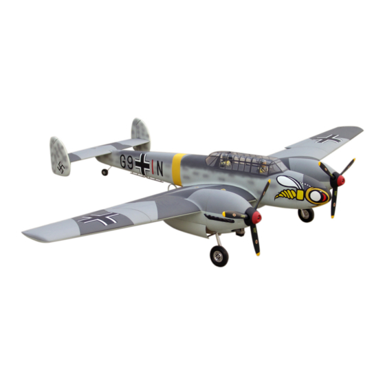
BF-110C ZERSTORER
Specification:
Length
:1817 mm(71.5")
Wing Span
:2413 mm(95")
Wing Area
:86.79/sq. dm
9.33/sq.ft
Wing Loading :103.78g/sq. dm
34.0oz/sq. ft
Flying Weight :9.0kg(19.8 lbs)
Radio
:6ch&11 servos(including two small one)
Engine(a pair) :91 4-cycle
SAFETY PRECAUTIONS
INSTRUCTION MANUAL
This R/C airplane is not a toy!
(The people under 18 years old is forbidden from flying this model)
First-time builders should seek advice from people having building
experience.If misused or abused,it can cause serious bodily injury
and damage to property.
Fly only in open areas and preferably at a dedicated R/C flying site.
We suggest having a qualified instructor carefully inspect your
airplane before its first flight.Please carefully read and follow all
instructions included with this airplane,your radio control system
and any other components purchased separately.
Advertisement

Related Manuals for Troy Built Models BF-110C ZERSTORER


Summary of Contents for Troy Built Models BF-110C ZERSTORER
-
Page 1: Instruction Manual
BF-110C ZERSTORER Specification: Length :1817 mm(71.5") Wing Span :2413 mm(95") Wing Area :86.79/sq. dm 9.33/sq.ft Wing Loading :103.78g/sq. dm 34.0oz/sq. ft Flying Weight :9.0kg(19.8 lbs) Radio :6ch&11 servos(including two small one) Engine(a pair) :91 4-cycle INSTRUCTION MANUAL This R/C airplane is not a toy! - Page 2 Mark the position in the landing gear cover and side Trim the shaded portion so that the bend cutting not fuselage for hatch hinges mount and hatch hinges. be blocked when the landing gear down. 150mm 40mm (with 13 servos), 155mm 6 channel radio for aiplane is highly recommended for this model.
- Page 3 Assemdle the pin hinge to appropriate position from Trim the shaded portions from side fuslage. Accessory list for the coming installation steps. Assemble the engine as below. inner landing gear corers. Nut (2mm ) Entad Washer (2x5mm) Screw (4x35mm) Washer (2x5mm) Screw (4x35mm) Ply (90x80x2mm) 21mm...
- Page 4 Move the bend cutting to appropriate position Recommend option gear doors installation step. Assembly of the fuel tank Assemble the throttle servos in the fuselage. and fix to landing gear. Thank you for purchasing ESM'S products. When we designed this model we have fore considered some of our customers who loves fly it with scale.
- Page 5 According to the rib template drill holes in the According to the rib template drill holes in the side-wings. Adjustment. Centre of Gravity. side-fuselages and epoxy the wood dowels in them. Wood dowel (4x30mm) Side View AILERON 20mm 20mm FLAP 40mm FLAP AILERON...
- Page 6 Epoxy the scale decorator parts to Install the servo as the illustration below Epoxy the pin hinges to the flap. Epoxy the main landing gear to the side fuselage. relevant position as below. Nut (3mm) Aluminum mounting Washer(3x6mm) Washer(3x6mm) Screw (3x20mm) Washer(3x6mm) Screw (3x20mm) Pin hinge (36x20x1mm)
- Page 7 Epoxy plies to relevant position inside the fuselage under Secure the servo.Install the nylon control horn Epoxy the decoration PVC parts to the relevant position. Trim the shade section of the belly pant for landing gear. the canopy and assemble the canopy with TP screw. and connect the linkage.
- Page 8 The illustration of the steel wire for tail wheel Fix the battery and receiver in the fuselage. Apply instant type CA glue to aileron and pin hinge. Epoxy the exhaust to the cowling from inner of the cowing. in the fuselage. Pin hinge(24x24mm) The openning direction of exhaust Steel wire (0.5x1200mm)
- Page 9 Secure the servo.Install the nylon control horn and Assemble the stabilizer to the fuselage and drill a hole in appropriate Install the servo as the illustration below Accessory list for the coming installation steps. connect the linkage. position through the stabilizer into the tail fuselage,set a blind nut in it. Steel wire (0.5x1200mm) 4.2mm TP Screw (2.3x12mm)
- Page 10 Fix the ply by the collars and notice the distance Join the detachable diddle wings together tightly Assemble the tail wheel to the tail landing gear. Assemble the outer-wing to side-wing tightly by the hook. between the ply and the steering arms. with the main wing joiner.
- Page 11 Trim the edge of the opening in the fuselage where According to the reinforcement drill holes under the Install the servo as the illustration below. Accessory list for the coming installation steps. the stabilizer be. back of middle wings and set blind nut in them. Clevis Reinforcement Retainer...
- Page 12 Assmble the elevator to the stabilizer with CA gule and The standard sketch map will be as below when The position of the control horn in the rudder. Assemble the rudder to the vertical tail with CA glue. the metal wire with epoxy glue. the horizontal tail install completion.
Need help?
Do you have a question about the BF-110C ZERSTORER and is the answer not in the manual?
Questions and answers