Advertisement
Quick Links
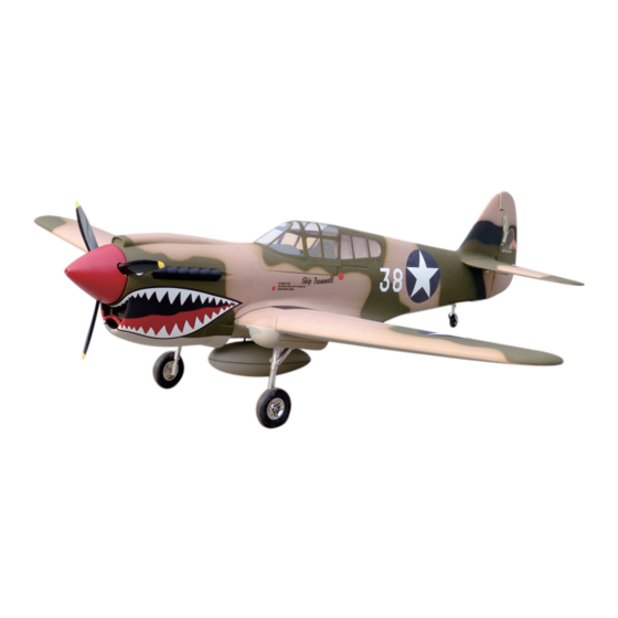
P-40 warhawk (50cc)
Specification:
Length:
1860mm(73.2")
Wing span:
2210mm(87")
Wing area:
74.75sq.dm(8.06sq.ft)
Wing loading: 140.5g/sq.dm(46.1oz/sq.ft)
Flying weight: 10.5kg(23lbs)
Radio:
6ch & 9servos
Engine:
50cc gasoline engine
SAFETY PRECAUTIONS
INSTRUCTION MANUAL
This R/C airplane is not a toy!
(The people under 18 years old is forbidden from flying this model)
First-time builders should seek advice from people having building
experience.If misused or abused,it can cause serious bodily injury
and damage to property.
Fly only in open areas and preferably at a dedicated R/C flying site.
We suggest having a qualified instructor carefully inspect your
airplane before its first flight.Please carefully read and follow all
instructions included with this airplane,your radio control system
and any other components purchased separately.
Advertisement

Subscribe to Our Youtube Channel
Related Manuals for Troy Built Models P-40 warhawk


Summary of Contents for Troy Built Models P-40 warhawk
- Page 1 P-40 warhawk (50cc) Specification: Length: 1860mm(73.2") Wing span: 2210mm(87") Wing area: 74.75sq.dm(8.06sq.ft) Wing loading: 140.5g/sq.dm(46.1oz/sq.ft) Flying weight: 10.5kg(23lbs) Radio: 6ch & 9servos INSTRUCTION MANUAL Engine: 50cc gasoline engine This R/C airplane is not a toy! (The people under 18 years old is forbidden from flying this model) First-time builders should seek advice from people having building experience.If misused or abused,it can cause serious bodily injury...
- Page 2 Gasoline tube Gasoline 6 channel radio for aiplane is highly recommended for this model. 50cc gas engine Optional parts: rubber wheel with metal hub. 6.25 in Spinner 22″X8-10 We strongly recommen you use the thread lock for all the screws when you build your model.
- Page 3 Assemble the aileron to main wing with instant type AB glue. Be careful Two wheel retract system Accessory list for the coming installation steps. to ensure the moving parts of the hinges are able to move freely. Clevis Make sure to assemble retracts as instructed below. Clevis Collar (3mm) Rod (2.5x300mm)
- Page 4 Keep some space about 1mm width between trailing Secure the servo.Install the nylon control horn and Adjustment. Adjustment. edge and flap. connect the linkage. TP Screw (2.3x12mm) Trailing edge Side View AILERON 30mm Rod (2.5x300mm) 1.5mm Flap Top view ELEVATOR 30mm Nut (3mm ) FLAP...
-
Page 5: Accessory List For The Coming Installation Steps
The sketch map when assemble the tail landing Accessory list for the coming installation steps. Install the nylon control horn and connect the linkage. Assembly of the main wings. gear to the wheel steeling mount. Tail wheel (45mm) Collar (3mm) Tail gear mount Wheel (115mm) Rod (2.5x300mm) - Page 6 Epoxy plies appropriate position inside the Epoxy the wheel cover to appropriate position Epoxy two parts and the plastic tubes in the holes. fuselage as below and assemble the cowling. Assemble the wheels to the retracts. around the retract as illustration. TP Screw (2.3x8mm) 1.5mm LockNut(4mm)
- Page 7 Epoxy plies to relevant position below the breaches Drill holes in the elevator and epoxy the pin Epoxy the wooden block to the breaches. Fix the wings to the fuselage. in the fuselage. hinges to them. Stab joiner (30x680mm) Pin hinge(4.5x67mm) Wooden Block (9mm) ply(3mm) Securely glue together.
- Page 8 Mounting the receiver and battery to appropriate According to the location wooden block and mark in the Install the nylon control horn and connect the linkage. Drill two holes in the stab root base on the rib template. position in the fuselage. cockpit through the holes in the location wooden block.
- Page 9 Epoxy the fuel tank in the fuselage. keep some space about 1mm width between Install the switch and the throttle servo Accessory list for the coming installation steps. Notice the position of the fuel tank in the fuselage. the vertical fin and rudder. Set screw (3x4mm) Vertical Clevis...
- Page 10 The side view when the engine install completion, Trim the surplus parts off the tail wheel cover carefully Drill a small hole to appropriate possition in the The sketch map of the steel wire for the rudder. and make sure the tail retract can get into the tail customers can adjust the engine to a appropriate fuselage for installing the plastical tube.
Need help?
Do you have a question about the P-40 warhawk and is the answer not in the manual?
Questions and answers