Advertisement
Quick Links
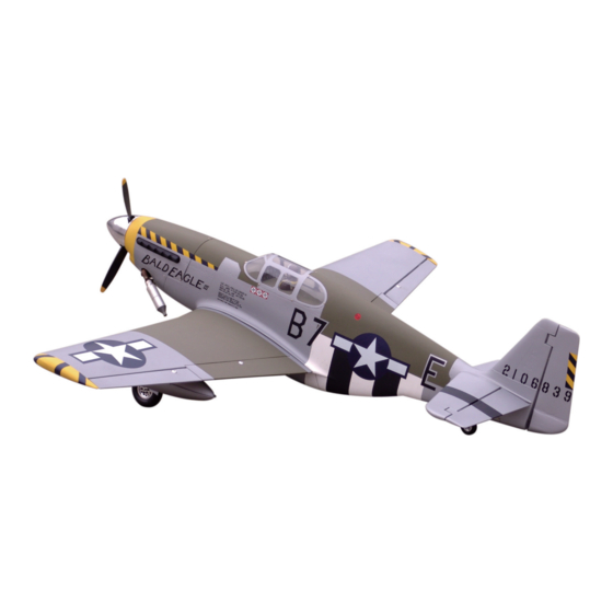
P-51B Mustang
Specification:
Length
:1583 mm(62.3")
Wing Span
:1800 mm(71")
Wing Area
:56.7 sq. dm
6.11 sq. ft
Wing Loading :100.5 g/sq. dm
33 oz/sq. ft
Flying Weight :5.7 kg(11.46 lbs)
Radio
:6ch&8 servos
Engine
:108 2-cycle
120 4-cycle
SAFETY PRECAUTIONS
INSTRUCTION MANUAL
This R/C airplane is not a toy!
(The people under 18 years old is forbidden from flying this model)
First-time builders should seek advice from people having building
experience.If misused or abused,it can cause serious bodily injury
and damage to property.
Fly only in open areas and preferably at a dedicated R/C flying site.
We suggest having a qualified instructor carefully inspect your
airplane before its first flight.Please carefully read and follow all
instructions included with this airplane,your radio control system
and any other components purchased separately.
Advertisement

Subscribe to Our Youtube Channel
Related Manuals for Troy Built Models P-51B Mustang


Summary of Contents for Troy Built Models P-51B Mustang
-
Page 1: Instruction Manual
P-51B Mustang Specification: Length :1583 mm(62.3") Wing Span :1800 mm(71") Wing Area :56.7 sq. dm 6.11 sq. ft Wing Loading :100.5 g/sq. dm 33 oz/sq. ft Flying Weight :5.7 kg(11.46 lbs) INSTRUCTION MANUAL Radio :6ch&8 servos Engine :108 2-cycle 120 4-cycle... - Page 2 (with 8 servos), 6 channel radio for aiplane is highly recommended for this model. : 4-cycle .120 Spinner nut " Pre-cover the covering with clean cloth! Warning Start at low setting. Increase the setting if Remove the covering with proper necessary.If it is too high,you may damage pressure to cut through only the covering itself.Otherwise, the film.
- Page 3 Assemble the aileron to main wing with instant type Accessory list for the coming installation steps. CA glue. Two wheel retract system Clevis Retainer Make sure to assemble retracts as instructed below. Rod (2x300mm) TP Screw (2.3x12mm) Screw (3x35mm) Servo tray(68.5x56.5x2mm) Wooden Block(20x20x8mm) Pin hinge(24x24mm) Washer(3x15mm)
- Page 4 Keep some space about 1mm width between trailing Secure the servo.Install the nylon control horn and Epoxy the wheels to the wings steadily. Adjustment. edge and flap. connect the linkage. TP Screw (2.3x12mm) Trailing edge Side View AILERON Rod (2x300mm) 1.5mm 20mm Flap...
-
Page 5: Accessory List For The Coming Installation Steps
Epoxy the drop tank to the bottom cover. Epoxy the too parts of the drop tank together. Install the nylon control horn and connect the linkage. Assembly of the main wings. Retainer Rod (2x300mm) A’ Clevis A=A’ Screw (2x10mm) B=B’ B’... - Page 6 According to the rib template drill holes in one wing and Trim the cowling for engine and muffler Cut off the surplus portion from the canopy carefully. Assemble the gear doors and the wheels to the retracts. epoxy wood dowel in them. LockNut(4mm) Bushing (8x4mm) Wooden Block...
- Page 7 Assemble the wheel steeling mounts to appropriate Drill holes to appropiate position in the wings and Epoxy the belly pants to main wing and drill holes to Connect the nose arm to the horn in the rudder. position. epoxy wood dowels in them relevant position on the belly pants Retainer 80 mm...
- Page 8 keep some space 1mm width between the vertical fin Keep some space about 1mm width between the The sketh amp of the steel wires in the fuselage Assemble the switch servo to the fuselage. and rudder elevator and horizontal tail edge. Tailing Vertical edge...
- Page 9 Set the U-style wire through the tail of fuselage as Drill holes to appropriate position in the stabilizer and Install the rudder servo. The position of the control horn in the rudder. below. epoxy it to the fuselahe as below. Washer(2x5mm) Screw (2x10mm) Ball joint...
- Page 10 Drill four holes at the diameters as shown for engine Accessory list for the coming installation steps. The sketch map when the engine install completion. Install the switch and the throttle servo mount. Set screw (3x4mm) Washer(2x5mm) Blind Nut (4mm) Clevis Clevis 5.2mm...
Need help?
Do you have a question about the P-51B Mustang and is the answer not in the manual?
Questions and answers