Table of Contents
Advertisement
Quick Links
72
Adjustment.
Top view
ELEVATOR
20mm
20mm
Position for
right diagram.
Two wheel retract system
Make sure to assemble retracts as instructed below.
3-way
pressure inlet
Strut
3-way
pressure inlet
Quick release connector
Pressure reduction inlet
Ø1.7mm
Please insure the sealing of the retract
system before flight .
Pleas notice the inner diameter for each
side of the pressure reduction inlet.
Switch
( 90 )
Strut
1
2
Air line (3000mm)
1
Retainer
3-way pressure inlet
1
3
Air tank
Clevis
1
Air valve
1
Air inlet
1
Rod (2X300mm)
Quick release connector
1
2
The status when the
Pressure reduction inlet
TP Screw(2x14mm)
gear up
2
1
73
The centre of the Gravity.
Never fly before checking CG's required position.
In order to obtain the CG specified reposition the
receiver and battery.
130mm
3-way
pressure inlet
Strut
Air inlet
Air tank
Quick release connector
Ø0.2mm
Sw i tch
Air valve
Pull out length of 8mm
to make gear down
14
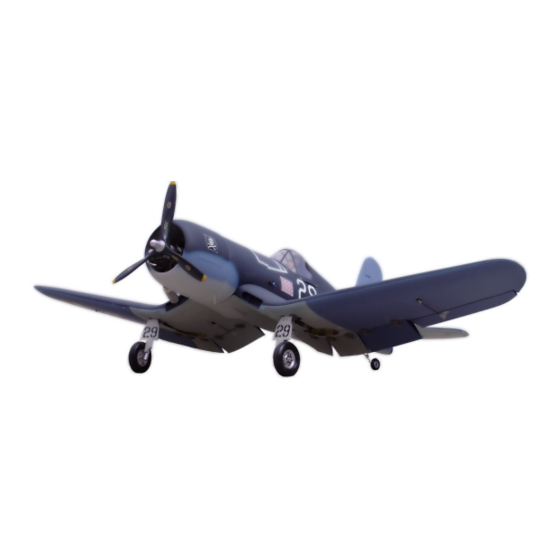
F - 4u Corsair
Specification:
Length
:1470 mm(57.9")
Wing Span
:1885 mm(74.2")
Wing Area
:62.13 sq. dm
6.7 sq. ft
Wing Loading :107.8 g/sq. dm
35.3 oz/sq. ft
Flying Weight :6.7 kg(14.7 lbs)
Radio
:6ch&8 servos
Engine
:120 4-cycle
SAFETY PRECAUTIONS
INSTRUCTION MANUAL
This R/C airplane is not a toy!
(The people under 18 years old is forbidden from flying this model)
First-time builders should seek advice from people having building
experience.If misused or abused,it can cause serious bodily injury
and damage to property.
Fly only in open areas and preferably at a dedicated R/C flying site.
We suggest having a qualified instructor carefully inspect your
airplane before its first flight.Please carefully read and follow all
instructions included with this airplane,your radio control system
and any other components purchased separately.
Advertisement
Table of Contents

Related Manuals for Troy Built Models F-4u Corsair


Summary of Contents for Troy Built Models F-4u Corsair
- Page 1 The centre of the Gravity. Adjustment. Never fly before checking CG’s required position. In order to obtain the CG specified reposition the receiver and battery. F - 4u Corsair Top view ELEVATOR 20mm 130mm 20mm Position for Side View right diagram. Two wheel retract system Make sure to assemble retracts as instructed below.
- Page 2 Epoxy plies under the canopy and assemble the Epoxy the fixed landing gear to the main wing. canopy to fuselage with screw. (with 8 servos), 6 channel radio for aiplane is highly recommended for this model. 1.5mm TP Screw (2.3x6mm) Ply (15x15x6mm) Accessory list for the coming installation steps.
- Page 3 Assemble the aileron to main wing with instant type Trim the cowling and canopy along the shaded line. Accessory list for the coming installation steps. Accessory list for the coming installation steps. CA glue. Clevis TP Screw (2.3x12mm) Retainer Rod (2x300mm) Canopy TP Screw (2.3x12mm) Screw (3x35mm)
- Page 4 Secure the servo.Install the nylon control horn and Assemble the elevator servo to appropriate position in Accessory list for the coming installation steps. Install the servo of switch in the fuselage. connect the linkage. the fuselage. Copper joiner TP Screw (2.3x12mm) Clevis Retainer 1.5mm...
- Page 5 Secure the servo.Install the nylon control horn and Pleas notice the position before assemble each hatch Install the switch and the throttle servo Install the rudder servo. connect the linkage. hinges. Washer(2x5mm) Screw (2x10mm) Set screw (3x4mm) 1.5mm Ball joint Add a rubber ring to the clevis for Lock Nut (2mm )
- Page 6 Drill four holes at the diameters as shown for engine Assembly of the main wings The sketch map when the engine install completion. Assemble the gear doors and the wheels to the retracts. mount. Bushing (8X4mm) LockNut(4mm) TP Screw (2.x10mm) A’...
- Page 7 Drill holes to appropriate position in the stabilizer and Drill two holes to the appropriate in the middle wing Accessory list for the coming installation steps. Accessory list for the coming installation steps. epoxy it to the fuselahe as below. and mount the dowels in them .
- Page 8 Epoxy the ply to appropriate position inside the tail of Keep some space about 1mm width between the Keep some space about 1mm width between the The sketh map of the steel wires in the fuselage fuselage vertical fin and rudder. elevator and horizontal tail edge.
Need help?
Do you have a question about the F-4u Corsair and is the answer not in the manual?
Questions and answers