Advertisement
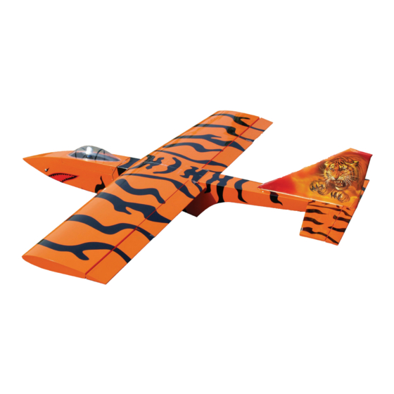
SHOCKJET ASSEMBLY MANUAL
MF MODELS 6/18/09
Specs........................................................................................................................ 1
Parts Needed........................................................................................................ 2, 3
Nosewheel Installation.......................................................................................... 3, 4
Turbine Installation................................................................................................ 5, 6
Tail............................................................................................................................ 7
Wing................................................................................................................... 7, 8, 9
Important Notes....................................................................................................... 10
Radio Setup............................................................................................................ 11
Turbine Starts........................................................................................................... 12
Wingspan
Length
Weight
Turbine
80.5"
73"
13 lbs
Super Bee 14 lb thrust
turbine or equivalent
1
Advertisement
Table of Contents

Summary of Contents for Troy Built Models SHOCKJET MF 6
-
Page 1: Table Of Contents
SHOCKJET ASSEMBLY MANUAL MF MODELS 6/18/09 Wingspan 80.5” Length 73” Weight 13 lbs Super Bee 14 lb thrust Turbine turbine or equivalent Table of Contents Specs........................1 Parts Needed......................2, 3 Nosewheel Installation..................3, 4 Turbine Installation....................5, 6 Tail..........................7 Wing........................ -
Page 2: Parts Needed
Models USA. If this is your first turbine powered aircraft and you need basic information, please see the Troy Built Models website and review the turbine overview webpage. This will provide you with a quick overview to make your turbine flying experience more enjoyable. -
Page 3: Nosewheel Installation
48” servo wire, 1-elevator 12” Y-harness, 1-flaps in fuse, 1-ailerons in fuse, 1-rudder/steering Battery: There are many options, the safest being 2 batteries and 2 switches, though this is generally the heaviest option. 4000 mah is necessary for 8-10 flights including start up and cool down. We recommend only the safest option which is a 4000+ mah battery with two switch leads which has sufficient burst to power the turbine start motor (Lipoly of Li Phos is better than Li Ion). - Page 4 Due to the low landing speeds achievable with this plane, a brake is not necessary, but it is a requirement by AMA, and it is very handy! Use the hole in the servo arm which is the closest to the servo shaft. Very little movement is required, and this puts less strain on the servo and battery.
-
Page 5: Turbine Installation
Turbine Installation Please see Page 6 for pictures referenced in this section. 1) Install the battery as shown under the front hatch. Route the wires forward to- wards the switch. 2) Install the components in the front of the fuselage. We suggest keeping the wiring neat by running as many wires as possible under the floor as shown. -
Page 7: Tail
Tail Section Tail Section: 1) Installing the fin and elevator is a simple matter of applying epoxy to the surfaces and gluing them in place. Before gluing, be sure that the fin is exactly centered in the fuselage. Use a square to ensure that the fin is perpendicular to the stab. - Page 8 INSTALL FRONT WING BOLT REINFORCEMENTS 1) The existing mounts can crush if the front wing bolts are over-tightened. The addition of the dowel eliminates this issue. Please do not over tighten the wing bolts. The front wing bolts are recessed into the wing .700”. These holes in the top of the wing are 3/8”...
- Page 9 Dry fit the wing halves together using the spar. When satisfied, apply Hysol to the wing joiner and mating surfaces. Be sure that the entire spar is covered with Hysol. It is especially important to get glue on the edges of the spar, not just the sides.
-
Page 10: Important Notes
Important! Before your first flight, and before the first flight after and changes or repairs, be sure that there are no loose foreign objects in the fuselage which can be sucked into the turbine. Hold the fuselage without the wing upside down and at various angles and shake it to remove any foreign debris. -
Page 11: Radio Setup
Radio Setup Following is the set up used in our JR radio. Rudder to Aileron and Elevator Mix: Due to the high stab, high rudder and high wing, the plane has proverse roll and pitch- es up with rudder. This can be easily mixed out. Please do so as soon as possible and leave these mixes on at all times. Trimming for pitch: The top of the fuselage and stab are defined to be 0 degrees. -
Page 12: Turbine Starts
More battery is used during shut down than at any other time. The battery cycles the starter motor for several minutes to cool the turbine. Hot fueling eliminates this cycling of the starter motor. Good Luck and be safe!! TROY BUILT MODELS 1650 Honore Ave. - Sarasota, FL 34232 941-342-8685...


Need help?
Do you have a question about the SHOCKJET MF 6 and is the answer not in the manual?
Questions and answers