Advertisement
Quick Links
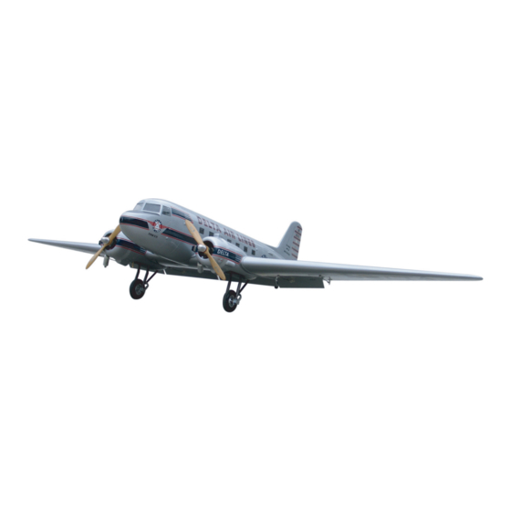
DC-3
Specification:
Length
:1790 mm(70.5")
Wing Span
:2640 mm(103.9")
Wing Area
:77.39 sq. dm
8.33 sq. ft
Wing Loading :116.3 g/sq. dm
38.1 oz/sq. ft
Flying Weight :9 kg(19.8 lbs)
Radio
:6ch&12 servos
Engine
:70 2-cycle
91 4-cycle
This R/C airplane is not a toy!
(The people under 18 years old is forbidden from flying this model)
First-time builders should seek advice from people having building
experience.If misused or abused,it can cause serious bodily injury
and damage to property.
Fly only in open areas and preferably at a dedicated R/C flying site.
SAFETY PRECAUTIONS
We suggest having a qualified instructor carefully inspect your
airplane before its first flight.Please carefully read and follow all
instructions included with this airplane,your radio control system
and any other components purchased separately.
INSTRUCTION MANUAL
Advertisement

Related Manuals for Troy Built Models DC-3


Summary of Contents for Troy Built Models DC-3
- Page 1 DC-3 Specification: Length :1790 mm(70.5") Wing Span :2640 mm(103.9") Wing Area :77.39 sq. dm 8.33 sq. ft Wing Loading :116.3 g/sq. dm 38.1 oz/sq. ft Flying Weight :9 kg(19.8 lbs) Radio :6ch&12 servos INSTRUCTION MANUAL Engine :70 2-cycle 91 4-cycle...
- Page 2 (with 12 servos), 6 channel radio for aiplane is highly recommended for this model. : 2-cycle .90-160 For float plane.160 size engine(2C)is highly recommended Spinner nut " Pre-cover the covering with clean cloth! Warning Start at low setting. Increase the setting if Remove the covering with proper necessary.If it is too high,you may damage pressure to cut through only the covering itself.Otherwise,...
- Page 3 Assemble the aileron to main wing with instant Accessory list for the coming installation steps. type CA glue. Clevis Retainer Rod (2x300mm) TP Screw (2.3x12mm) Screw (3x35mm) Servo tray(68.5x56.5x2mm) Wooden Block(20x20x8mm) Pin hinge(24x24mm) Washer(3x15mm) Lock Nut (3mm ) Washer(3x15mm) Securely glue together. If coming off during flights, you 'll lose control of your airplane which leads to accidents! Install the servo as the illustration below Apply instant type CA glue to aileron and pin hinge.
- Page 4 Leave some space with width of 1mm between Secure the servo.Install the nylon control horn and Centre of Gravity. Adjustment. connect the linkage. trailing edge and flap. TP Screw (2.3x12mm) 1.5mm Trailing edge Side View 120mm Flap Rod (2x300mm) RUDDER 25mm Screw (2x10mm) Lock Nut (3mm )
- Page 5 Mount the receiver and the battery to the fuselage. Epoxy the flap to the main wings. Accessory list for the coming installation steps. Install the nylon control horn and connect the linkage. PVC Part Retainer Rod (2x300mm) PVC Part Clevis Screw (2x10mm) PVC Part PVC Part...
- Page 6 Accessory list for the coming installation steps. Connect the linkage rod to the horn. Accessory list for the coming installation steps. Install the servo as the illustration below Screw (4x40mm) Screw (4x35mm) Rod (2x300mm) Screw (4x30mm) Wheel (100 mm) Washer(4x8mm) Spring Washer (4mm) Landing gear(5mm) Nut (4mm)
- Page 7 The sketch map of the the push rod assemble Assemble the rudder to the vertical tail with AB glue. Drill seven holes as show for engine mount. The sketch map of the elevator servo. completion Washer(2x5mm) Screw (2x10mm) Ball joint 2.5mm Lock Nut (2mm ) 5.2mm...
- Page 8 The sketch map of the the tail wheel install completion. Assemble the throttle servos in the fuselage. Accessory list for the coming installation steps. Cut off the shaded portion in the Mid wing. Retainer Copper joiner Washer(2x5mm) Clevis Fiber glass pushr od (3x890mm) Copper joiner TP Screw (2.3x8mm)
- Page 9 Make sure the horizontal tail are cleanly before epoxy it to Assemble the tail landing gear The working sketch map of the retract. Trim the cowling for engine and muffler. fuselage and make sure it be assemble to the right position . Stab Joiner(16x300mm) Tail landing gear Collar...
- Page 10 Assemble the elevator to the horizontal tail by CA glue. Drill holes to relevant position in the fuselage as below. According to the rib template drill holes to the mid wing. The standard sketch map when the horizonal install completion. Make sure to glue securely.
Need help?
Do you have a question about the DC-3 and is the answer not in the manual?
Questions and answers