Advertisement
Quick Links
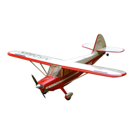
Stinson 108
Specification:
Length
:1689 mm(66.5")
Wing Span
:2311 mm(91")
Wing Area
:72sq.dm
7.7sq.ft
Wing Loading :81.9g/sq.dm
26.9oz/sq.ft
Flying Weight :5.9kg(13.1lbs)
Radio
:6ch & 8servos
Engine:
:26cc-30cc
SAFETY PRECAUTIONS
INSTRUCTION MANUAL
This R/C airplane is not a toy!
(The people under 18 years old is forbidden from flying this model)
First-time builders should seek advice from people having building
experience.If misused or abused,it can cause serious bodily injury
and damage to property.
Fly only in open areas and preferably at a dedicated R/C flying site.
We suggest having a qualified instructor carefully inspect your
airplane before its first flight.Please carefully read and follow all
instructions included with this airplane,your radio control system
and any other components purchased separately.
Advertisement

Related Manuals for Troy Built Models Stinson 108


Summary of Contents for Troy Built Models Stinson 108
-
Page 1: Instruction Manual
Stinson 108 Specification: Length :1689 mm(66.5") Wing Span :2311 mm(91") Wing Area :72sq.dm 7.7sq.ft Wing Loading :81.9g/sq.dm 26.9oz/sq.ft Flying Weight :5.9kg(13.1lbs) INSTRUCTION MANUAL Radio :6ch & 8servos Engine: :26cc-30cc This R/C airplane is not a toy! (The people under 18 years old is forbidden from flying this model) First-time builders should seek advice from people having building experience.If misused or abused,it can cause serious bodily injury... - Page 2 (with 8 servos), 6 channel radio for aiplane is highly recommended for this model. : 4-cycle .120 2.5 in Spinner " Pre-cover the covering with clean cloth! Warning Start at low setting. Increase the setting if Remove the covering with proper necessary.If it is too high,you may damage pressure to cut through only the covering itself.Otherwise, the film.
- Page 3 .Assemble the door window with instant style glue. Adjustment of the rudder, be sure it can work perfectly. Apply instant type AB glue to appropriate position in the Accessory list for the coming installation steps. trailing edge and assemble the ailerons to them. Rod (2.5x300mm) TP Screw (2.3x12mm) Servo tray(70x58x2mm)
- Page 4 Assemble the landing gears cover to the fuselage with Assemble the cowling carefully to the head of fuselage Apply instant type AB glue to the control horn and the slots in Keep about 1mm width space between trailing edge TP screws. with TP screws.
-
Page 5: Accessory List For The Coming Installation Steps
Drill holes to appropriate position in the wheel pants, Accessory list for the coming installation steps. Install the control horn and connect the linkage. The standard sketch map when the kit install completion. fixing the wheel pants to the landing gear with screws. Make sure to glue securely. - Page 6 Fix the wing to fuselage with screws throught the holes Keep about 1mm width space between elevator The sketch map when the engine install completion. Assembly of the fuel tank. and trailing edge. applied in the wings and fuselage. Screw Tailing edge Spring Washer...
- Page 7 Install the engine mount tubes to the fuselage,lock them The front view once the engine install completion. Assemble the servo of elevator to the servo mount. Fix the stabilizers to the tail fuselage via screws. from inside of the fuselage. Washer(3x6mm) Screw (4x45mm) Washer(4x8mm)
- Page 8 Lock the linkage to the control horn with screws and nuts According to the illustration below bend the tail landing Epoxy the rudder to the vertical fin.. The sketch map of how the steel wires works for the rudder. gear wire and cut off the surplus part. as below.
Need help?
Do you have a question about the Stinson 108 and is the answer not in the manual?
Questions and answers