Advertisement
Quick Links
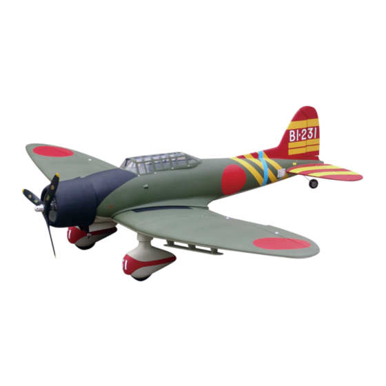
Aichi D3A1
Specification:
Length:
1540mm(60.6")
Wing span:
2057mm(81")
Wing area:
76.1sq.dm(8.2sq.ft)
Wing loading: 99.9g/sq.dm(32.8oz/sq.ft)
Flying weight: 7.6kg(16.7lbs)
Radio:
6ch & 7servos
Engine:
120 4-cycle
C.G:
135mm
This R/C airplane is not a toy!
(The people under 18 years old is forbidden from flying this model)
First-time builders should seek advice from people having building
experience.If misused or abused,it can cause serious bodily injury
and damage to property.
Fly only in open areas and preferably at a dedicated R/C flying site.
SAFETY PRECAUTIONS
We suggest having a qualified instructor carefully inspect your
airplane before its first flight.Please carefully read and follow all
instructions included with this airplane,your radio control system
and any other components purchased separately.
INSTRUCTION MANUAL
Advertisement

Related Manuals for Troy Built Models Aichi D3A1


Summary of Contents for Troy Built Models Aichi D3A1
- Page 1 Aichi D3A1 Specification: Length: 1540mm(60.6") Wing span: 2057mm(81") Wing area: 76.1sq.dm(8.2sq.ft) Wing loading: 99.9g/sq.dm(32.8oz/sq.ft) Flying weight: 7.6kg(16.7lbs) Radio: 6ch & 7servos INSTRUCTION MANUAL Engine: 120 4-cycle C.G: 135mm This R/C airplane is not a toy! (The people under 18 years old is forbidden from flying this model) First-time builders should seek advice from people having building experience.If misused or abused,it can cause serious bodily injury...
- Page 2 6 channel radio for aiplane is highly recommended for this model. 4-cycle .180 Optional parts: rubber wheel with metal hub. 15″X7 Spinner nut We strongly recommen you use the thread lock for all the screws when you build your model.
-
Page 3: Accessory List For The Coming Installation Steps
Apply instand type CA glue to appropriate position of Accessory list for the coming installation steps. trailing edge and pin hinge. Clevis Retainer Rod (2x300mm) TP Screw (2.3x12mm) Screw (3x40mm) Pin hinge(24x24mm) Washer(3x15mm) Lock Nut (3mm ) Washer(3x15mm) Securely glue together. If coming off during flights, you 'll lose control of your airplane which leads to accidents! Apply instant type CA glue to appropriate position of Fix the aileron servo to the serve tray with epoxy. - Page 4 Secure the servo.Install the nylon control horn Adjustment. Adjustment. Assemble the flap servo to the main wing with screws. and connect the linkage. TP Screw (2.3x12mm) TP Screw (2.3x12mm) Side View AILERON Rod (2x300mm) 20mm Side View 20mm 1.5mm FLAP RUDDER Lock Nut (3mm ) 30mm...
- Page 5 Connect the two flaps with metal wire,keep some space Epoxy main wings to the centre wing by main wing Fix the fairing part to the fuselage with screw. Drill holes to relevant pesition in the centet wing. between them and epoxy the pinned hinges to the flaps joiners.
- Page 6 Epoxy plies under the canopy and assemble the Epoxy the dummy parts to the appropriate position Assemble the arms in the flaps the servo arms to them Drill holes in the fuselage for installing the wings. canopy to fuselage with screw. in the mid wing.
- Page 7 Epoxy the wooden form to appropriate in the cowling. Assembly of the switch servo. Accessory list for the coming installation steps. Mount wheel pant and tire. Wooden Block(110x82x9mm) Wheel (140mm) Wheel pants 15mm Former Wheel (140mm) Collar (6mm) Collar (6mm) 10mm Wooden Block(110x82x9mm) 147mm...
- Page 8 Set the U-style wire through the tail of fuselage as Accessory list for the coming installation steps. Mount the fuel tank into the fuselage. Assemble the throttle linkage. below. Linkage Stopper Stab joiner (12x280mm) Steel wire (0.5x3000mm) Set Screw (3x4mm) U-style wire (150x3mm) Wood dowel (4x30mm) Washer (2mm)
- Page 9 Epoxy plies to appropriate position in the fuselage. Keep some space about 1mm width between the Install the nylon control ring for switch and The side view of the engine install completion. Then assemble the wheel as illustration. elevator and horizontal tail edge. connect the linkage.
- Page 10 Epoxy a wooden block to inner fuse tail for helping Accessory list for the coming installation steps. Epoxy pin hinges to rudder. Install the rudder servo. fix the landing gear mount. Tail landing gear mount Washer(2x5mm) Screw (2x10mm) Ball joint Wooden Block (3mm Ply) Tail landing gear(3mm) 2.5mm...
Need help?
Do you have a question about the Aichi D3A1 and is the answer not in the manual?
Questions and answers