Table of Contents
Advertisement
Quick Links
graphic
graphic
70
Stick the graphic to appropriate position on the fuselage.
71
Stick the graphic to appropriate position on the fuselage.
69
The step once you stick the graphic on fuselage completion.
Clear the surface of the fuselage with clear white
cloth once you stick the grasphics on the plane.
1
1
14
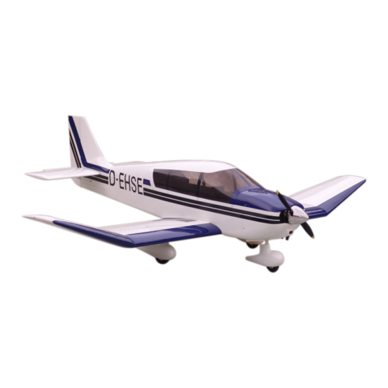
ROBIN DR400
Specification:
(ITEM NO: WO34A)
Length
:2170 mm(85.5")
Wing Span
:2577 mm(101")
Wing Area
:113 sq. dm
12.15 sq. ft
Wing Loading :113.6 g/sq. dm
37.2oz/sq. ft
Flying Weight :12500 g(27.5 lbs)
Radio
:6ch & 8 servos
Engine
:80—100CC Gasoline engine
SAFETY PRECAUTIONS
INSTRUCTION MANUAL
This R/C airplane is not a toy!
(The people under 18 years old is forbidden from flying this model)
First-time builders should seek advice from people having building
experience.If misused or abused,it can cause serious bodily injury
and damage to property.
Fly only in open areas and preferably at a dedicated R/C flying site.
We suggest having a qualified instructor carefully inspect your
airplane before its first flight.Please carefully read and follow all
instructions included with this airplane,your radio control system
and any other components purchased separately.
Advertisement
Table of Contents

Related Manuals for Troy Built Models ROBIN DR400


Summary of Contents for Troy Built Models ROBIN DR400
- Page 1 Accessory list for the coming installation steps. The step once you stick the graphic on fuselage completion. ROBIN DR400 Clear the surface of the fuselage with clear white graphic cloth once you stick the grasphics on the plane. graphic Stick the graphic to appropriate position on the fuselage.
- Page 2 Epoxy plies to appropriate position on the fuselage which under the canopy and assemble the canopy to fuselage Adjustment. with TP screws. TP Screw (2.3x8mm) AILERON (with 8 servos), 20mm 20mm FLAP 6 channel radio for aiplane is highly recommended for this model. 30mm 1.5mm TP Screw (2.3x8mm)
- Page 3 Assemble the aileron to main wing with instant type CA glue.Be careful Accessory list for the coming installation steps. The sketch map when the servos install completion. Trim the cowling for engine and muffler. to ensure the moving parts of the hinges are able to move freely. Clevis Rudder servo Retainer...
- Page 4 Secure the servo.Install the nylon control horn and Keep some space about 1mm width between Drill a hole and slot to the rod and glue the wire to Accessory list for the coming installation steps. connect the linkage. trailing edge and flap. them and wrap it with tape.
- Page 5 Keep some space about 1mm width between Epoxy the plastical tubes to the holes as illustration. Install the nylon control horn and connect the linkage. The sketch map when the wings assemble completion. the tailing edge and the rudder. Make sure to glue securely. If not properly glued, a failure in flight may occur.
- Page 6 Put the metal arms,wheel adapters & wood mount in the Assemble the side wing to the main wing and fix them Assemble the wings to the fuselage and fix it with Fix the wheel adapters with set screw and wood tail fuselage,let the stab tube through all these parts.
- Page 7 According to the rib template drill a hole one the Accessory list for the coming installation steps. Accessory list for the coming installation steps. Assemble the throttle servo in the fuselage. main wheel pants. Pin hinge(2.5x48mm) Clevis Stab tube(16x690mm) TP Screw (2.3x8mm) Wheel (100mm) Aluminum tube(3x6mm) wheel adapters...
- Page 8 Drill 4 holes to appropriate position in the head According to the rib template drill a hole to the nose Drill two holes to appropriate position in the firewall Accessory list for the coming installation steps. fuselage and set blind nut in them.. wheel pants.
Need help?
Do you have a question about the ROBIN DR400 and is the answer not in the manual?
Questions and answers