Table of Contents
Advertisement
Quick Links
Repair
™
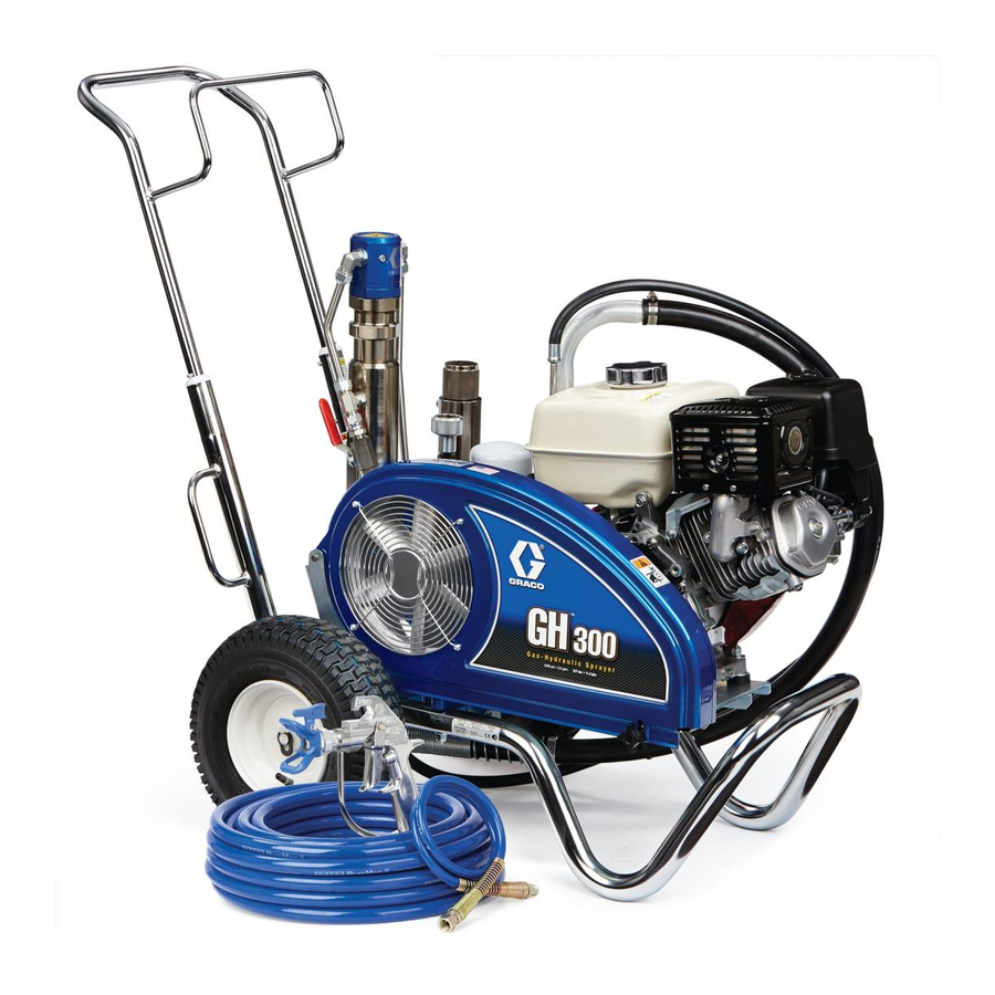
DutyMax
- Not approved for use in European explosive atmosphere locations -
Models: 24M054 (EH200DI), 24M055 (GH200DI), 24M056 (EH300DI), 24M057 (GH300DI)
3300 psi (22.8 MPa, 228 bar) Maximum Working Pressure
Important Safety Instructions
Read all warnings and instructions in this
manual. Save these instructions.
See page 3 for model information.
3A2246
311845
3A2248
308491 - Blue Texture Gun
309495 - Inline Texture Gun
Hydraulic Sprayers
- For professional use only -
3A2247A
EN
ti18188a
Advertisement
Table of Contents

Related Manuals for Graco DutyMax 24M054


Summary of Contents for Graco DutyMax 24M054
- Page 1 Repair ™ 3A2247A DutyMax Hydraulic Sprayers - For professional use only - - Not approved for use in European explosive atmosphere locations - Models: 24M054 (EH200DI), 24M055 (GH200DI), 24M056 (EH300DI), 24M057 (GH300DI) 3300 psi (22.8 MPa, 228 bar) Maximum Working Pressure Important Safety Instructions Read all warnings and instructions in this manual.
-
Page 2: Table Of Contents
Installation ......20 Graco Standard Warranty ....32... -
Page 3: Models
Models Models EH300DI GH200DI GH300DI EH200DI INLINE GUN 240 VAC BLUE GUN 3/8 in. x 12 in. WHIP 400VAC 50 Hz 1/4 in. x 3 ft WHIP 1/2 in. x 50 ft HOSE 50 Hz 1 Phase 3/8 in. x 50 ft HOSE 3 Phase ✔... - Page 4 Models Warnings The following warnings are for the setup, use, grounding, maintenance, and repair of this equipment. The exclama- tion point symbol alerts you to a general warning and the hazard symbols refer to procedure-specific risks. When these symbols appear in the body of this manual or on warning labels, refer back to these Warnings. Product-specific hazard symbols and warnings not covered in this section may appear throughout the body of this manual where applicable.
- Page 5 • Check hoses and parts for signs of damage. Replace any damaged hoses or parts. • This system is capable of producing 3300 psi. Use Graco replacement parts or accessories that are rated a minimum of 3300 psi. • Always engage the trigger lock when not spraying. Verify the trigger lock is functioning properly.
- Page 6 Models WARNING MOVING PARTS HAZARD Moving parts can pinch, cut or amputate fingers and other body parts. • Keep clear of moving parts. • Do not operate equipment with protective guards or covers removed. • Pressurized equipment can start without warning. Before checking, moving, or servicing equipment, follow the Pressure Relief Procedure and disconnect all power sources.
- Page 7 Models WARNING TOXIC FLUID OR FUMES HAZARD Toxic fluids or fumes can cause serious injury or death if splashed in the eyes or on skin, inhaled, or swallowed. • Read MSDSs to know the specific hazards of the fluids you are using. •...
-
Page 8: General Repair Information
General Repair Information General Repair Information Grounding Ground sprayer with grounding clamp to earth ground for safe sprayer operation. DANGER HIGH VOLTAGE ELECTRIC SHOCK HAZARD This equipment uses high voltage power. Improper contact with high voltage equipment will cause death or serious injury. -
Page 9: Pressure Relief Procedure
SEMI-ANNUALLY: Check belt wear, replace if necessary. YEARLY OR 2000 HOURS: Replace belt. Replace hydraulic oil and filter with Graco hydraulic oil 169236 (5 gallon/20 liter) or 207428 (1 gallon/3.8 liter) and filter 116909. SPARK PLUG: Use only BPRGES or W20EPR-U (NIPPONDENSO) plugs. -
Page 10: Troubleshooting
1 phase motors: Turn on/off switch to ON. 3 phase motors: Push ON switch. Incorrect power source Have a certified electrician or authorized Graco Repair Center evaluate and repair. See Technical Data, page 30. NOTE: If using the EH300DI (24M056) sprayer, the generator must be sized for 15 kW output minimum. - Page 11 Excessive hydraulic pump noise Low hydraulic fluid level Turn sprayer OFF. Add fluid*. Air in hydraulic lines Bleed lines. See Repair manual. *Check hydraulic fluid level often. Do not allow it to become too low. Use only Graco approved hydraulic fluid. 3A2247A...
-
Page 12: Hydraulic Pump
Hydraulic Pump Hydraulic Pump Removal 5. Raise electric motor (or gas engine) and remove belt (44). This equipment stays pressurized until pressure is manually relieved. To help prevent serious injury from pressurized fluid, such as skin injection, splashing fluid and moving parts, follow the Pressure Relief Procedure when you stop spraying and before cleaning, checking, or servicing the equipment. -
Page 13: Installation
(173). 10. Install drain plug (202). Install oil filter (227); tighten 3/4 turn after gasket contacts base. Fill hydraulic pump with Graco hydraulic oil, page 6, through elbow (221) port until full. Fill reservoir with remain- ti18356a ing hydraulic oil. -
Page 14: Fan Belt
Fan Belt Fan Belt Removal 4. Lift electric motor or gas engine up to remove ten- sion on belt (44). 5. Remove belt from pulley (43) and fan pulley (96). Installation This equipment stays pressurized until pressure is manually relieved. To help prevent serious injury from 1. -
Page 15: Electric Motor Starter
Electric Motor Starter Electric Motor Starter Removal DANGER 3 Phase, 400 VAC, 50 Hz, Electric Motor Starter HIGH VOLTAGE ELECTRIC SHOCK HAZARD This equipment uses high voltage power. Improper contact with high voltage equipment will cause death or serious injury. •... -
Page 16: Installation
Electric Motor Starter 5. Remove motor junction box cover (J). Installation 6. Tilt motor junction box cover back and disconnect 3 Phase, 400 VAC, 50 Hz, Electric Motor Starter three power leads (brown, black, and grey wires) and the yellow and green ground wire (see Wiring Diagram, page 29). - Page 17 Electric Motor Starter 7. Be sure gasket is in position on motor junction box 10. Swing electric motor retainer bracket (204) in. cover. Connect yellow and green ground wire to Tighten electric motor nut (205). motor junction box ground connection. Connect power leads as follows: •...
-
Page 18: Electric Motor
Electric Motor Electric Motor Removal 1 Phase, 240 VAC, 50 Hz Electric Motor DANGER HIGH VOLTAGE ELECTRIC SHOCK HAZARD This equipment uses high voltage power. Improper contact with high voltage equipment will cause death or serious injury. • Turn off and disconnect power cord before servicing equipment. - Page 19 Electric Motor 3 Phase, 400 VAC, 50 Hz, Electric Motor 3. Loosen electric motor nut (205). Swing motor retainer bracket (204) out. ti5384a 4. Remove motor assembly from sprayer. ti18617a ti18749a 5. Remove motor junction box cover (J). 6. Tilt motor junction box cover back and disconnect three power leads (brown, black, and grey wires) 1.
-
Page 20: Installation
Electric Motor Installation 3. Install motor assembly on sprayer. 1 Phase, 240 VAC, 50 Hz Electric Motor ti18193a 4. Swing electric motor retainer bracket (204) in. Tighten electric motor nut (205). ti18343a ti5387a 5. Install Fan Belt, page 14. 6. Check to make sure fan pulley and motor pulley are in line. - Page 21 Electric Motor 3 Phase, 400 VAC, 50 Hz, Electric Motor 6. Slide strain relief fitting (S) over motor cable power leads. 7. Screw strain relief fitting (5) into motor junction box cover (J). ti18700a 8. Be sure gasket is in position on motor junction box cover.
- Page 22 Electric Motor 11. Swing electric motor retainer bracket (204) in. Tighten electric motor nut (205). Motor Pulley (133) FLUSH (Motor pulley to end of motor shaft) ti5387a Motor Shaft 12. Install Fan Belt, page 14. Parallel 13. Check to make sure fan pulley and motor pulley are in line.
-
Page 23: Hydraulic Motor Rebuild
40 ft-lb (54.2 N•m). 5. Do Displacement Pump, Installation, page 27. 6. Start engine and operate pump for 30 seconds. Turn engine OFF. Check hydraulic oil level and fill with Graco hydraulic oil, page 25. 3A2247A... -
Page 24: Hydraulic Motor
Hydraulic Motor Rebuild Hydraulic Motor test hole ti8817A ti8818a 3A2247A... -
Page 25: Hydraulic Oil/Filter Change
1. Install drain plug (202) and oil filter (227). Tighten oil ti18348a filter 3/4 turn after gasket contacts base. 2. Fill with five quarts of Graco hydraulic oil 169236 (5 gallon/20 liter) or 207428 (1 gallon/3.8 liter). 3. Check oil level. -
Page 26: Displacement Pump
Displacement Pump Displacement Pump NOTE: It is recommended that the check valve be 6. Open clamp (247). repaired at the same time as the pump. For check valve repair, see manual 3A2338. Removal ti8833b 7. Slide coupler cover (180) up to fully expose rod cou- This equipment stays pressurized until pressure is plers (179). -
Page 27: Installation
Displacement Pump Installation 1. If needed, place pump rod in adjustment casting 5. Slide coupler cover (180) up to expose pump rod. and pull pump to lengthen rod. Install rod couplers (179) over rod. ti8834b 2. Install pump (111) in sprayer. ti8956b 6. -
Page 28: Check Valve Repair
Check Valve Repair Check Valve Repair 2. Use 1.5 in. (38 mm) wrench to securely tighten check valve to pump. This equipment stays pressurized until pressure is manually relieved. To help prevent serious injury from pressurized fluid, such as skin injection, splashing fluid and moving parts, follow the Pressure Relief Proce- dure when you stop spraying and before cleaning, checking, or servicing the equipment. -
Page 29: Wiring Diagram
Wiring Diagram Wiring Diagram EH300 Models (3 Phase Motor) ti18616a 3A2247A... -
Page 30: Notes
Technical Data Technical Data EH200DI U.S. Metric Maximum Pressure psi (bar) 3300 Hydraulic Reservoir Capacity Gallons (Liters) 1.25 4.75 Motor HP (kW) 220 VAC, 15.0 220 VAC, 15.0 Voltage, Amperage Frequency Phase A, 50 Hz, A, 50 Hz, 1 Phase 1 Phase Maximum Tip size (paint) 0.039... -
Page 31: Technical Data
Technical Data GH200DI U.S. Metric Maximum Pressure psi (bar) 3300 Hydraulic Reservoir Capacity Gallons (Liters) 1.25 4.75 Motor HP (kW) Maximum Tip size (paint) 0.047 0.047 Maximum Delivery (paint) gpm (lpm) 2.15 Fluid Inlet in. [npsm (m)] Fluid Outlet in. [npsm (m)] Hose Connection [npt (f)] Cycles per gallon (l) (paint) 21.1... - Page 32 Technical Data EH300DI U.S. Metric Maximum Pressure psi (bar) 3300 Hydraulic Reservoir Capacity Gallons (Liters) 1.25 4.75 Motor HP (kW) 400 VAC, 400 VAC, 11.0 A, 11.0 A, Voltage, Amperage Frequency Phase 50 Hz, 50 Hz, 3 Phase 3 Phase Maximum Tip size (paint) 0.057 0.057...
- Page 33 Technical Data GH300DI U.S. Metric Maximum Pressure psi (bar) 3300 Hydraulic Reservoir Capacity Gallons (Liters) 1.25 4.75 Motor HP (kW) Maximum Tip size (paint) 0.057 0.057 Maximum Delivery (paint) gpm (lpm) 11.3 Fluid Inlet in. [npsm (m)] Fluid Outlet in. [npsm (m)] Hose Connection [npt (f)] Cycles per gallon (l) (paint) 13.7...
-
Page 34: Graco Standard Warranty
With the exception of any special, extended, or limited warranty published by Graco, Graco will, for a period of twelve months from the date of sale, repair or replace any part of the equipment determined by Graco to be defective.
Need help?
Do you have a question about the DutyMax 24M054 and is the answer not in the manual?
Questions and answers