Table of Contents
Advertisement
Quick Links
Instructions - Parts
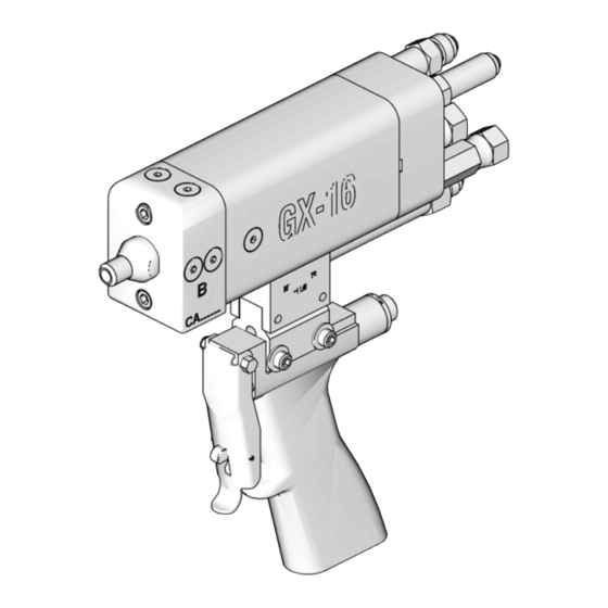
GX-16
For dispensing polyol and isocyanate materials only. For indoor use only. Not for use in
explosive atmospheres. For professional use only.
2000 psi (14 MPa, 138 bar) Maximum Fluid Working Pressure
2500 psi (17 MPa, 172 bar) Maximum Hydraulic Working Pressure
180°F (82°C) Maximum Fluid Temperature
Important Safety Instructions
Read all warnings and instructions in this
manual. Save these instructions.
Model 257496 shown
313536A
ENG
ti12896a
Advertisement
Table of Contents

Related Manuals for Graco GX-16


Summary of Contents for Graco GX-16
- Page 1 Instructions - Parts GX-16 313536A For dispensing polyol and isocyanate materials only. For indoor use only. Not for use in explosive atmospheres. For professional use only. 2000 psi (14 MPa, 138 bar) Maximum Fluid Working Pressure 2500 psi (17 MPa, 172 bar) Maximum Hydraulic Working Pressure 180°F (82°C) Maximum Fluid Temperature...
-
Page 2: Table Of Contents
Graco Standard Warranty ....34 Graco Information ......34... -
Page 3: Models
GX-16 Pour Gun, 24:1, Pour Handle, Left Side Chemical Tubes, Star-Shaped Trigger Switch Connector 257494 GX-16 Pour Gun, 24:1, Pour Handle, Right Side Chemical Tubes, Cir- cular Trigger Switch Connector 257495 GX-16 Pour Gun, 24:1, Pour Handle, Left Side Chemical Tubes, Circu-... -
Page 4: Warnings
Warnings Warnings The following warnings are for the setup, use, grounding, maintenance, and repair of this equipment. The exclama- tion point symbol alerts you to a general warning and the hazard symbol refers to procedure-specific risk. Refer back to these warnings. Additional, product-specific warnings may be found throughout the body of this manual where applicable. - Page 5 Warnings WARNING EQUIPMENT MISUSE HAZARD Misuse can cause death or serious injury. • Do not operate the unit when fatigued or under the influence of drugs or alcohol. • Do not exceed the maximum working pressure or temperature rating of the lowest rated system component.
-
Page 6: Important Two-Component Material Information
Keep the ISO lube pump reservoir (if installed) filled impermeable gloves, boots, aprons, and goggles, is with Graco Throat Seal Liquid (TSL), Part 206995. also required for everyone in the work area. The lubricant creates a barrier between the ISO and the atmosphere. -
Page 7: Changing Materials
Important Two-Component Material Information Changing Materials • When changing materials, flush the equipment mul- tiple times to ensure it is thoroughly clean. • Always clean the fluid inlet strainers after flushing. • Check with your material manufacturer for chemical compatibility. •... -
Page 8: Grounding
Grounding Grounding Fluid supply container: follow local code. Solvent pails used when flushing: follow local code. Use only conductive metal pails, placed on a grounded surface. Do not place the pail on a non-conductive sur- The equipment must be grounded. Grounding reduces face, such as paper or cardboard, which interrupts the risk of static and electric shock by providing an grounding continuity. -
Page 9: Setup
Setup Setup Gun Connections ti12897a Description Tape Color Fitting Size 7/16 ORG x A Pressure Line #6 JIC Female 7/16 ORG x A Return Line Red and White #6 JIC Male 7/16 ORG x B Pressure Line Blue #5 JIC Female 7/16 ORG x B Return Line Blue and White... -
Page 10: Fluid Line
Setup Fluid Line NOTE: Pressure should not increase while air is purged from hoses. Fluid Filter: Use a 25 micron stainless steel element to 5. Turn off power pack. Verify no pressure exists in filter particles from the fluid as it leaves the pump. hoses. -
Page 11: Coupling Block Setup
12. Install chemical hoses to gun. See F . 3 on page 9 Mounting and F . 7. Use the following mounting dimensions to mount the GX-16 gun body. ti14494a ti14493a A Width: 1.125 in. (28.58 mm) Coupling Block Setup B Diameter: 0.159 in. -
Page 12: Startup
Startup Startup 1. If your setup uses the optional coupling block 8. Dispense a test shot into a waste container. assembly, use a 3/8 in. wrench to set the coupling 9. Clean any residual material from the tip of the gun. block valves to the “open”... -
Page 13: Operation
Operation Operation Theory of Operation Dispense Circulation Key: A Pressure Line Key: A Return Line A Pressure Line B Pressure Line A Return Line B Return Line B Pressure Line Hydraulic Open Line B Return Line Hydraulic Close Line Hydraulic Open Line Piston Rod Hydraulic Close Line Hydraulic Piston... -
Page 14: Pressure Relief Procedure
Pressure Relief Procedure Pressure Relief Shutdown Procedure 1. Perform Pressure Relief Procedure. 2. Perform any required maintenance. See Mainte- 1. If your setup uses the optional coupling block nance on page 15. assembly, use a 3/8 in. wrench to set the coupling block valves to the “open”... -
Page 15: Maintenance
Maintenance Maintenance Procedure Frequency Inspect the gun, fluid lines, trigger switch cable Daily and, if installed, the proximity switch cable for wear or damage Grease the gun Weekly Clean and service the orifices and filters As Needed Recommended Tools 3. Use a grease gun, part 117792, with the required synthetic grease, part 117773, to purge the gun body until grease exits the weep hole without evi- •... -
Page 16: Clean And Service The Orifices And Filters
Maintenance Clean and Service the Orifices 2. If your setup uses the optional coupling block assembly, use 3/8 in. wrench to close the coupling and Filters block manual valves. 3. Use a 7/16 in. wrench to remove the orifice. 4. Use a 1/8 in. allen key to remove the cleanout plug next to the orifice. -
Page 17: Proximity Switch Replacement Procedure
Maintenance Proximity Switch Replacement Procedure 1. Perform pressure relief procedure. See Pressure Relief Procedure on page 14. 2. Remove proximity switch cable attached to proximity switch. 3. Remove proximity switch from rear of gun body. ti12897a . 16 4. Install new proximity switch. 5. -
Page 18: Troubleshooting
Faulty proximity switch Replace proximity switch Damaged piston u-cup seals Send gun to Graco for repair Chemical crossover Seal failure on piston rod Send gun to Graco for repair Hydraulic leak into divorce chamber... - Page 19 Troubleshooting 313536A...
-
Page 20: Parts
Parts Parts Gun Models 257496, 257498, 257499, 257505, 257506, 257507 101a, c 101b, d ti12900a Model 257496 shown 313536A... - Page 21 257496 257498 257499 257505 257506 257507 257513 DISPENSER, GX-16, 1:1, pre-assy 257514 DISPENSER, GX-16, 24:1, pre-assy 257515 DISPENSER, GX-16, rev block, pre-assy . 101a◆ . 122685 . PLUG, sae02, socket head, m, ms, 6k . 101b◆ . 261500 . O-RING, #902, fluoroelastomer .
-
Page 22: Gun Models 257492, 257493, 257494, 257495
Parts Gun Models 257492, 257493, 257494, 257495 216 215 201a, c 201b, d ti12901a Model 257492 shown 313536A... - Page 23 257492 257493 257494 257495 Part Description 257514 DISPENSER, GX-16, 24:1, pre-assy . 201a◆ . 122685 . PLUG, sae02, socket head, m, ms, 6k . 201b◆ . 261500 . O-RING, #902, fluoroelastomer . 201c◆ . 122687 . PLUG, sae02, 316 ss .
-
Page 24: Gun Models 257497, 257502, 257503, 257504
Parts Gun Models 257497, 257502, 257503, 257504 301a, c 301b, d Model 257504 shown ti13381a 313536A... - Page 25 Quantity by Model Part Description 257497 257502 257503 257504 257513 DISPENSER, GX-16, 1:1, pre-assy 257514 DISPENSER, GX-16, 24:1, pre-assy . 301a◆ . 122685 . PLUG, sae02, socket head, m, ms, 6k . 301b◆ . 261500 . O-RING, #902, fluoroelastomer . 301c◆...
- Page 26 Parts Dispenser Models 257513, 257514, 257515 ti14490a Model 257513 shown 313536A...
-
Page 27: Dispenser Models 257513, 257514, 257515
Parts Quantity 257515, Dispenser, 257513; 257514; 24:1, Dispenser, Dispenser, Reverse Part Description 24:1 Block 295229 FITTING, grease, 1/4-28 420* 122685 PLUG, sae02, skt hd, m, ms, 6k 261500 O-RING, #902, fluoroelastomer 422* 122687 PLUG, sae02, 316 ss 122685 PLUG, sae02, skt hd, m, ms, 6k 122679 O-RING, epr, #902 261500... -
Page 28: Gun Handle Models 257509, 257510
Parts Gun Handle Models 257509, 257510 ti13383a Model 257510 shown Part Description 257576 HANDLE 112095 SCREW, set 257578 SWITCH, trigger 299650 SPRING 257577 PLUNGER, spring 15Y159 NUT, retainer 257579 TRIGGER, safety, gun 295671 SCREW, mounting, trigger 295438 NUT, stop, elastic, 5-40 15Y160 ISOLATOR, handle (Model 257510 only) -
Page 29: Pour Handle Models 257594, 257596
Parts Pour Handle Models 257594, 257596 Model 257594 shown ti14499a Part Description 295438 NUT, stop, elastic, 5-40 122746 SCREW, shc, 10-32x.375, ms, nyloc 257595 CONTROL, circular connector/led (assembly 257594 only) 257597 CONTROL, star-shaped connector/led (assembly 257596 only) 295671 SCREW, mounting, trigger 15Y276 CLIP, expander, female 257593... -
Page 30: Optional Coupling Block, 257912
Parts Optional Coupling Block, 257912 ti14489a Part Description 122987 O-RING, #012, EPR, 90D 122959 O-RING, #P-5, EPR, 90D 106555 PACKING, O-RING 299286 O-RING, #P-5 15Y808 PLUG, valve rod 15Y793 BLOCK, coupling, remote 15Y235 BLOCK, coupling, base, remote 15Y764 PLATE, block 113008 PIN, downl, 0.125 dia. -
Page 31: Accessories
Accessories Accessories Description Part Hose Kit 24C999 Gun Cover, straight fittings 123694 Gun Cover, 90 deg. fittings 124226 Hose Cover, 12 ft 123698 313536A... -
Page 32: Technical Data
Technical Data Technical Data Maximum Fluid Working Pressure ....2000 psi (14 MPa, 138 bar) Maximum Hydraulic Working Pressure ....2500 psi (17 MPa, 172 bar) Maximum Fluid Temperature . -
Page 33: Dimensions
Technical Data Dimensions ti12896a Model 257496 shown Dimension Model 257492, 257493, 15.1 (383) 9.6 (244) 7.9 (201) 257494, 257495 257497, 257502, 257503, 257504 10.3 (262) 3.6 (91) 3.7 (94) (no hoses) 257496, 257507 9.3 (236) 3.0 (76) 8.9 (226) 257505, 257506 9.3 (236) 3.0 (76) 8.1 (206) -
Page 34: Graco Standard Warranty
With the exception of any special, extended, or limited warranty published by Graco, Graco will, for a period of twelve months from the date of sale, repair or replace any part of the equipment determined by Graco to be defective.
Need help?
Do you have a question about the GX-16 and is the answer not in the manual?
Questions and answers