Page 1
Repair 
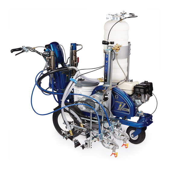
Compressor Replacement for 3A7388B ™ ™ LineLazer 200 and LineLazer For use on LineLazer Line Stripers to replace compressor used with Pressurized Bead System. For professional use only. Model for LL200: 25R271 Model for LL250: 25R272 Important Safety Instructions Read all warnings and instructions in this manual and in your Complete Pressurized Bead System Installation manual before using the equipment.
Warnings Warnings The following warnings are for the setup, use, grounding, maintenance, and repair of this equipment. The exclamation point symbol alerts you to a general warning and the hazard symbols refer to procedure-specific risks. When these symbols appear in the body of this manual or on warning labels, refer back to these Warnings.
Page 4
Warnings WARNING BURN HAZARD Equipment surfaces and fluid that is heated can become very hot during operation. To avoid severe burns: • Do not touch hot fluid or equipment. PERSONAL PROTECTIVE EQUIPMENT Wear appropriate protective equipment when in the work area to help prevent serious injury, including eye injury, hearing loss, inhalation of toxic fumes, and burns.
Pressure Relief Procedure Pressure Relief Procedure 3. Loosen wing nut (2) until it reaches end of threads. Follow the Pressure Relief Procedure whenever If any remaining pressure is in bead tank, it will be you see this symbol. released through seal while wing nut secures lid to hopper.
LL200 Compressor Removal LL200 Compressor Removal Tools Needed: 1/8 in. Allen wrench, 9/16 in. wrench. 6. Using a 9/16 in. wrench, remove four screws between compressor bracket and frame. Remove compressor. To prevent injuries from burns, let unit cool prior to working on it.
LL200 Compressor Installation LL200 Compressor Installation Tools Needed: 2.5 mm Allen wrench, 4.0 mm Allen 5. Using same bolts (bb) and lock nuts (22), install air wrench, 1/4 in. Allen wrench, 7/16 in. wrench, 9/16 in. tank bracket (3). wrench, 11/16 in. wrench, T-20 star bit, rubber mallet, Phillips screwdriver.
Page 8
LL200 Compressor Installation 6. With a 9/16 in. wrench, mount air tank to air tank 8. Remove hopper. Locate belt shroud. Loosen knob bracket with screws. When correctly installed, air and rotate shroud. tank will sit farther forward than the previous installation.
Page 9
LL200 Compressor Installation 13. Torque pulley set screws to 58-62 in-lb (6.6-7 N•m) 16. Use existing screws to install fan grill (FF) back onto belt shroud. Do not over-tighten screws. Make sure 14. Install belt on pulley. Refer to Ground Drive Belt fan grill protrudes out;...
Page 10
LL200 Compressor Installation 17. Position compressor bracket (4) with three tabs 19. Slowly pull the starter rope to rotate shaft so that the facing towards the fan grill. Center shaft coupler shaft keyway (5) faces up. Place the key (2) into the both vertically and horizontally in slot.
Page 11
LL200 Compressor Installation 20. Slide compressor onto the shaft coupler mounting 21. Use two carriage bolts, two washers, and two nuts plate until the face of the compressor is flush with in opposing holes (180 degrees apart) to tighten the compressor bracket.
Page 12
LL200 Compressor Installation 22. Slowly pull the starter rope to rotate shaft until the 24. With the compressor secured to the coupler two M8x10 set screws appear in the set screw mounting plate, slightly loosen the four mounting access. Torque the set screws to 150-160 in-lb screws (20).
Page 13
LL200 Compressor Installation 26. Apply thread sealant paste to threads of tee fitting 29. If unit is equipped with a drain plug, remove drain (6). Install tee fitting with safety valve (7) into plug and verify oil is visible on threads of drain port. compressor output.
LL250 Compressor Removal LL250 Compressor Removal Tools Needed: 1/8 in. Allen wrench, 9/16 in. wrench. 6. Using a 9/16 in. wrench, remove three screws (VV) on the compressor bracket. To prevent injuries from burns, let unit cool prior to working on it. 1.
LL250 Compressor Installation LL250 Compressor Installation Tools Needed: 2.5 mm Allen wrench, 4.0 mm Allen 5. Using a 9/16 in. wrench and screws, mount the air wrench, 1/4 in. Allen wrench, 7/16 in. wrench, 9/16 in. tank to the new air tank bracket. wrench, 11/16 in.
Page 16
LL250 Compressor Installation 7. Remove hopper. Locate belt shroud. Loosen screw NOTE: Before performing step 14, secure nuts to back (A) and lift belt shroud (B). of pulley with piece of duct tape to assist with installation. 14. Put belt shroud down. Install coupler mounting plate (5) onto pulley with two shoulder screws (18) and serrated nuts (19).
Page 17
LL250 Compressor Installation 15. Use existing screws, nuts, and washers to install fan 16. Remove two existing bolts and washers from striper grill (FF) back onto bet shroud. Do not over-tighten frame. Install compressor bracket with three tabs screws. Make sure fan grill protrudes out; not into facing towards fan grill using existing washers and the belt shroud.
Page 18
LL250 Compressor Installation 17. Place drop of medium strength thread locker on the threads of each set screw. Using a 2.5 mm and a NOTICE 4.0 mm Allen wrench, screw the set screws into the Performing steps 19 through 23 out of order, or shaft collar far enough so that the shaft collar can incorrectly, may cause excessive side loading on the slide on the compressor shaft sleeve.
Page 19
LL250 Compressor Installation 20. Use two carriage bolts (8), two washers (9), and two 21. Using a long screw driver, slowly rotate the fan nuts (16) in opposing holes (180 degrees apart) to pulley until the two M8x10 set screws appear in the tighten the compressor to the compressor bracket.
Page 20
LL250 Compressor Installation 23. With the compressor secured to the coupler 25. Apply thread sealer to threads of tee fitting (6). mounting plate, slightly loosen the two mounting Install tee fitting with safety valve (7) into screws between the frame and bracket. Install all compressor output.
Page 21
LL250 Compressor Installation 27. Install air filter. Hand tighten. 28. If unit is equipped with a drain plug, remove drain plug and verify oil is visible on threads of drain port. If not full, fill with included oil through drain port until visible on threads.
Maintenance Maintenance Routine maintenance is important to ensure proper operation of your compressor. Maintenance includes performing routine actions to keep your compressor in operation and prevent trouble in the future. Activity Interval Replace air filter Every 200 hours, or as needed Change oil* After first 50 hours, then every 200 hours or three months * Drain oil by siphoning from fill port.
With the exception of any special, extended, or limited warranty published by Graco, Graco will, for a period of twelve months from the date of sale, repair or replace any part of the equipment determined by Graco to be defective.
Page 29
Graco Standard Warranty Graco Information For the latest information about Graco products, visit www.graco.com. For patent information, see www.graco.com/patents. TO PLACE AN ORDER, contact your Graco distributor or call 1-800-690-2894 to identify the nearest distributor. 3A7388B...
Page 30
Original instructions. This manual contains English. MM 3A788 Graco Headquarters: Minneapolis International Offices: Belgium, China, Japan, Korea GRACO INC. AND SUBSIDIARIES • P.O. BOX 1441 • MINNEAPOLIS MN 55440-1441 • USA Copyright 2018, Graco Inc. All Graco manufacturing locations are registered to ISO 9001. www.graco.com...
Need help?
Do you have a question about the LineLazer 200 and is the answer not in the manual?
Questions and answers