Graco SD Series Repair And Parts Manual
Hide thumbs
Also See for SD Series:
- Instructions manual (60 pages) ,
- Installation and operation instructions manual (36 pages) ,
- Repair and parts manual (36 pages)
Table of Contents
Advertisement
Repair and Parts
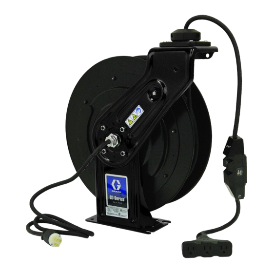
SD Series
and Light Reel
For storing electric cord used to provide electricity and/or light. For indoor and dry
location use only.
Not approved for use in explosive atmospheres or hazardous locations.
Models: pages 3 and 4
X
Important Safety Instructions
Read all warnings and instructions in this
manual and in SD Series Cord and Light Reel
Installation manual. Save all instructions
Size 5 Model
™
Cord
.
Size 10 Model
3A2826E
EN
Advertisement
Table of Contents

Related Manuals for Graco SD Series


Summary of Contents for Graco SD Series
- Page 1 Not approved for use in explosive atmospheres or hazardous locations. Models: pages 3 and 4 Important Safety Instructions Read all warnings and instructions in this manual and in SD Series Cord and Light Reel Installation manual. Save all instructions Size 10 Model Size 5 Model...
-
Page 2: Table Of Contents
Notes ........35 Graco SD Series™ Cord and Light Reel Warranty 36... -
Page 3: 120 Volt Models
120 Volt Models 120 Volt Models Power Cord Cord Model Description Size Length Insulation Connect Accessory Wire Gauge Current Blue Black (AWG) (Amperes) Size 5 Size 10 50 feet NEMA SJTOW 24M510 24Y858 15 meters 5-15P 95 feet NEMA SJTOW 24M511... -
Page 4: 230 Volt Models
230 Volt Models 230 Volt Models Cord Power Cord Model Description Size Length Insulation Connect Accessory Current Blue Black Wire Gauge (Amperes) Size 5 Size 10 24M514 24Y873 10 meters H05RR-F 1,5 mm Cord, No 24M515 24Y874 15 meters H05RR-F 1,5 mm Accessory ... -
Page 5: Warnings
Warnings Warnings The following warnings are for the setup, use, grounding, maintenance, and repair of this equipment. The exclama- tion point symbol alerts you to a general warning and the hazard symbols refer to procedure-specific risks. When these symbols appear in the body of this manual or on warning labels, refer back to these Warnings. Product-specific hazard symbols and warnings not covered in this section may appear throughout the body of this manual where applicable. - Page 6 Warnings FIRE AND EXPLOSION HAZARD When flammable fluids are present in the work area, such as gasoline and windshield wiper fluid, be aware that flammable fumes can ignite or explode. To help prevent fire and explosion: • When installing a cord reel above a hazardous location the reel must be mounted at such a height that the lamp guard cannot reach within 18 inches of the floor.
-
Page 7: Component Identification
Component Identification Component Identification Key: Spool Power Cord Accessory Cord Cord Stop Base Plate Support Arm cutaway view - part is located behind support arm) Pawl ( 3A2826E... -
Page 8: Adjusting Spring Tension
Component Identification Adjusting Spring Tension Table 1: Recommended Number of Pre-Turns Model Blue Black No. of Turns • Never allow reel to spin freely. Doing so could 24M510 24M858 cause serious injury if you are hit by the plug, 24M511 24M879 accessories, or other moving parts. -
Page 9: Troubleshooting
Troubleshooting Troubleshooting Problem Cause Solution Outlet attachment is too heavy Increase spring tension. See Increasing Spring Tension, page 8. Spring lost tension Cord will not retract fully Replace spring. See Replacing Spring is broken Spring Cassette instructions, page Replace spring. See Replacing Spring is broken Spring Cassette, page 11. - Page 10 Troubleshooting Problem Cause Solution Check electrical rating on reel label. Application does not conform to the Do not attempt to use a reel that is electrical rating of the reel Breaker or fuse trip out (GFCI not rated for the application. accessory or European models Wires are broken or shorted Replace all damaged wires.
-
Page 11: Repair
Repair Repair Replacing the Spring Cassette the hub (b) must maintain the direction as shown in . 3. Kits: 24M452, 24M453, 24M454, 24M455, 24M460, 24M462, 24M463 Reference letters used in the following procedure refer to the kit parts table below and Parts page 26. See Parts pages for additional information regarding kits and their related models. -
Page 12: Replacing The Accessory Cord
Repair Replacing the Accessory Cord ELECTRIC SHOCK HAZARD All electrical wiring must be done by a qualified electri- cian and comply with all local codes and regulations. Kits†: 24N882, 24N885, 24N886, 24N887, 24N888, 24N889, 24N890, 24N891, 24N892, 24N893, 243N894, 24N895, 24N896 Reference letters used in the following procedure refer to the kit parts table below and Parts page 26. - Page 13 Repair Take special care not to damage power cord when loosening hex nut. A damaged power cord presents a threat of electric shock and a fire hazard. 8. Pull spool assembly away from arm and pedestal. 9. For Size 5 models: Loosen six 10 mm hex nuts Top View (20) and remove cover (36).
- Page 14 Repair 12. For 230V models only disconnect the brown wire (A) from the over current protection device (47). Remove wire from “LOAD” side of device. (F . 8) 13. Loosen 10 mm hex nut (20) to relieve tension on cord clamp (33) (F .
- Page 15 Repair Reassembly 1. Route new cord (101a) through grommet (44) and cord clamp (33). Tighten 10 mm hex nut to 6 in-lbs (3 N.m) on cord clamp (33) to hold the cord in place securely (F . 7, page 13). NOTE: Ensure there is enough extra cord between cord clamp and slip ring before securing cord clamp (33).
- Page 16 Repair 10. Mount spool assembly into arm and pedestal taking care to ensure keyed shaft aligns with arm and ped- estal. Ensure washer is in place as shown in F Incorrect washer (8) keyed Correct shaft . 12 . 13 11.
-
Page 17: Electrical Power Cords
Repair Electrical Power Cords ELECTRIC SHOCK HAZARD All electrical wiring must be done by a qualified electri- cian and comply with all local codes and regulations. Kits: 24N866, 24N867, 24N868, 24N869, 24N870 Reference letters used in the following procedure refer to the kit parts table below and Parts page 26. - Page 18 Repair Reassembly NOTE: Test each crimp by performing a pull test on each conductor to ensure proper crimp. 1. Route power cord (102a) through strain relief nut (5), cord stop (102d), 34 mm hex nut (4), star 4. Mount terminal rings (102c) to appropriate mounting washer (27) through pedestal arm, washer (8), and stud as shown in F .
-
Page 19: Slip Ring Replacement
Repair 6. Continue reassembly procedure for Replacing the Slip Ring Cord Instructions, Steps 7 - 18, page 15. 4. In order to remove slip ring (21), disassembly of spring cassette is required. Remove spring cas- Slip Ring Replacement sette. Continue Disassembly with Steps 1-3 of the Replacing the Spring Cassette section on page 11 of this manual. - Page 20 Repair 2. Align set screw holes (A) on shaft (7) with proper 7. Remove tool (103c) from assembly (F . 25). holes on new slip ring. Tighten set screw to hand tight. 3. Re-install ground lug and wire between position 1 on slip ring and ground lug on shaft (7).
-
Page 21: Single Industrial Receptacle
Repair Single Industrial Receptacle 120V Models NEMA 5-20R (24N871) . 27: Viewed from the back 5. Slide receptacle into housing. 6. Replace and tighten 3 screws on front of receptacle. 7. Install strain relief and tighten screws. . 26 8. Plug reel back in and test. Disassembly 230 Models CEE 7/7 16 Receptacle (24N872) 1. -
Page 22: Fluorescent Light (16N223)
Repair 4. Loosen two phillips screws for strain relief. Fluorescent Light with Tool Tap 5. Loosen three screws to wire terminals. Remove (16N224) wire. For repair instructions, see instructions provided with Reassembly light. 1. Route wire through protective shell. 2. Install brown wire in left wiring terminal and tighten screw. -
Page 23: Led Light 120V (127088)
Repair LED Light 120V (127088) LED Light 230V (16N225) For repair instructions, see instructions provided with For repair instructions, see instructions provided with light. light. . 31 . 33 Tool Tap 120V (16N226) For repair instructions, see instructions provided with light. -
Page 24: Tri-Plug Gfci Industrial Receptacle(24N880)
Repair Tri-Plug GFCI Industrial Receptacle(24N880) Disassembly Reassembly 1. Disconnect cord reel from power source by unplug- 1. Route cord through enclosure panel and through ging main supply plug from outlet. opening in roller guide. 2. Loosen two Phillips #2 screws (A) on GFCI cover 2. -
Page 25: Replacement Bulbs
Repair Replacement Bulbs For 230V LED Lights - 16P1696 For Fluorescent Lights - 16P697 Assembly Disassembly . 37 . 36 Disassembly Disassembly 1. Disconnect cord reel from power source by unplug- 1. Disconnect cord reel from power source by unplug- ging main supply plug from outlet. -
Page 26: Parts Size 5 Shown
Parts Size 5 shown Parts Size 5 shown 12 9 3A2826E... -
Page 27: Size 5 And Size 10 Models
Parts Size 5 shown Size 5 and Size 10 Models See page 29 for a complete list of kits referenced in the following parts table. REF Kit No. Description REF Kit No. Description 105a SPRING, ratchet pawl BASE, welded, Size 5 models 105b BOLT, M10 x 25 lg w patch BASE, welded, Size 10 models... - Page 28 Parts Size 5 shown REF Kit No. Description REF Kit No. Description RIVET, aluminum, 4mm, not shown GROMMET, diaphragm, 12 AWG, 106e 2.5 mm , not shown, models HUB, cord reel, 3550, Size 5 mod- 107e 24M512, 24M513 24M516, 24M521, 24M522, 24M523, HUB, cord reel, 7500, Size 10 mod- 24M524, 54M525, 24M526, 24M544, 24Y859,...
-
Page 29: Kits
Parts Size 5 shown Kits REF Kit No. Description 24N871 SOCKET, single, NEMA, 5-20R, Part No. Description not shown, models 24M521-24M524, 24Y862, KIT, spring cassette, Size 5, mod- 24M452 24Y863, 24Y881, 24Y882 els 24M518, 24Y861 CORD, protector-to-carbon brush, KIT, spring cassette, Size 5 mod- not shown, models els 24M514, 24M517, 24M527, 24M514-24M516,... - Page 30 Parts Size 5 shown Part No. Description Part No. Description 101a CORD 24N882 KIT, cord, 1.5 mm , 25 M, models 101b TERMINAL, ring 24M541, 24Y890 101c TERMINAL, insulated 24N885 KIT, cord, 50 feet, 16 AWG, SJTOW, models 24M510, 24N866 KIT, power cord, NEMA 5-15P, 16 24M528, 24M531, 24M534, AWG, models 24M510, 24M511, 24M537, 24Y858, 24Y866,...
- Page 31 Parts Size 5 shown Part No. Description Part No. Description 105c BUSHING, pawl CLAMP, wire, 16 AWG, 1.5 mm models 24M510, 24M514, 105d PAWL, ratchet 106h 24M515, 24M517, 24M518, 105e NUT, lock 24M527, 24M528, 24M530, 24M531, 24M533, 24M534, 24M536, 24M537, 24M539, 24N540 KIT, seal and wire clamping, 24M540, 24M542, 24M543, Size-5...
- Page 32 Parts Size 5 shown Part No. Description 108d SCREW, M6 x 16 222225 KIT, repair, ball stop, 12 AWG and 2.5 mm cord 24N539 KIT, repair, ball stop, 16AWG cord 24N538 KIT, repair, ball stop, 1.5 mm cord 109a NUT, hex 109b SCREW, mach.
-
Page 33: Technical Data
Technical Data Technical Data ™ Size 5 and Size 10 SD Series Cord and Light Reel 120V Models 230V Models Voltage 120VAC 230VAC Maximum Current See Models, page 3 See Models, page 4 Wire Gauge See Models, page 3 See Models, page 4... -
Page 34: Dimensions - Size 5 And Size 10 Models
Technical Data Dimensions - Size 5 and Size 10 Models Size E† F G 3.5 inches 6.38 inches 4.7 inches 7.48 inches 14.8 inches 6.6 inches 13.84 inches Size 5 (89 mm) (162 mm) (120 mm) (190 mm) (376 mm) (168 mm) (352mm) 3.5 inches... -
Page 35: Notes
Notes Notes 3A2826E... -
Page 36: Graco Sd Series™ Cord And Light Reel Warranty
Graco warrants all equipment referenced in this document which is manufactured by Graco and bearing its name to be free from defects in material and workmanship on the date of sale to the original purchaser for use. Graco will, for a period of two (2) years from the date of sale, repair or replace any non-electrical components of the equipment determined by Graco to be defective, and Graco will for a period of one (1) year from the date of sale, repair or replace any electrical components of the equipment determined by Graco to be defective.
Need help?
Do you have a question about the SD Series and is the answer not in the manual?
Questions and answers