Table of Contents
Advertisement
Quick Links
KS150/190/215-SD Installation Guide
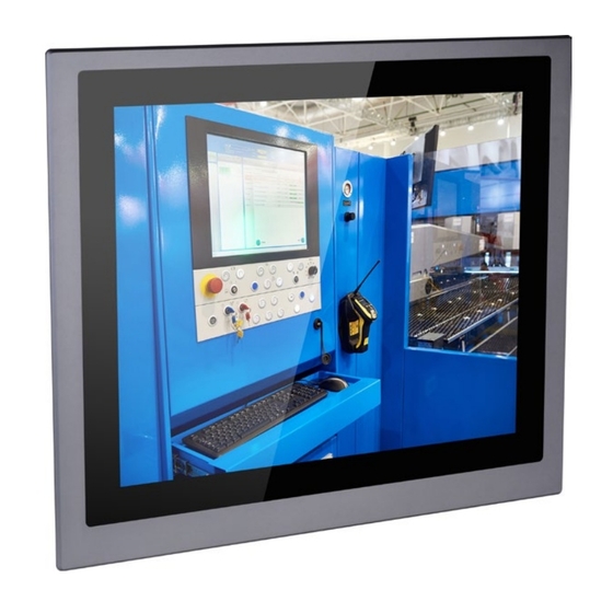
• One 15", 19", or 21.5" Modular Touch Panel PC
• 3-pin Terminal Blcok Connector
• SATA and Mini PCIe Installation Screws
DFI reserves the right to change the specifications at any time prior to the
product's release. For the latest revision and more details of the installation
procedure, please refer to the user's manual on the website.
Package Contents
www.dfi.com
1
Advertisement
Table of Contents

Related Manuals for DFI KS150


Summary of Contents for DFI KS150
-
Page 1: Package Contents
• 3-pin Terminal Blcok Connector • SATA and Mini PCIe Installation Screws DFI reserves the right to change the specifications at any time prior to the product's release. For the latest revision and more details of the installation procedure, please refer to the user's manual on the website. - Page 2 Panel Bottom View Status LED (Orange) HDD LED (Red) COM 2 COM 1 Power Button Remote Power Switch COM 3 COM 4 Reset Button Top View DVI-D LAN 1 LAN 2 (DVI-I connector) USB 3.0 DC-in Front OSD Functions (only for models with front OSD) Power HDD Alarm LED Backlight or Power Brightness...
-
Page 3: Removing The Chassis Cover
Removing the Chassis Cover 1. Make sure the system and all other peripheral devices connected to it have been powered-off. 2. Disconnect all power cords and cables. 3. The 6 mounting screws on the rear side of the system are used to secure the cover to the chassis. -
Page 4: Installing A Sata Drive
Installing a SATA Drive The system can accommodate one SATA drive. Please use the following procedure to install a SATA drive in the system. 1. Before installing the SATA drive, connect the SATA data/power cable to the SATA data connector of the SATA drive. Then install the SATA drive onto the HDD bracket with the provided mounting screws. - Page 5 3. Connect the other end of the SATA data/power cable to the SATA data and power connectors on the system board respectively. SATA data connector SATA power connector...
-
Page 6: Installing A Sodimm
Installing a SODIMM The system supports two DDR4 SODIMM socket. To install a memory mod- ule, grasp the memory module by its edges and align the module’s notch with the socket’s notch; then insert the memory into the socket at an angle and push it down until you feel a click. - Page 7 Installing a Mini PCIe or mSATA Card The system board is equipped with 2 Mini PCIe slots: one full-size and (PCIe/USB signals) and one half-size slot (USB/mSATA signals). Here we will demonstrate the installation of a full-size Mini PCIe card. 1.
- Page 8 Important: The bottom side of a full-size Mini PCIe module should have a component height restriction of 0.82 mm and will sit flush against the connected half-size Mini PCIe module if such a component is used and the half-size slot is connected with a module.
- Page 9 Assemble the Modular Panel PC The modular panel PC comprises two parts: a box module and a panel module. 1. Take off the cover of the ADP connector. Hold the box module with its ADP connector (female) in line with the ADP connector (male) of the panel module.
- Page 10 3. Seat the box module on top of the panel module with the alignment post effortlessly sliping into the designated holes on the box module. Press to install these two modules and secure the installation with 8 mouting screws. Mounting Screw Alignment Post Mounting Screw...
-
Page 11: Mounting Options
Mounting Options VESA mount The VESA-mount specifications for this device is 100 x 100 (mm). Please use a compatible VESA mount kit that can sustain the weight and size of this device. The VESA mount kit includes the following: • 2 VESA mount brackets •... - Page 12 4. The system has designed Attach the other bracket (VESA mount bracket 2) to the rear of the Panel PC. Thumb screw Hooks VESA mount bracket 2 Mounting screw 5. Slide the Panel PC to "wall mount bracket 1" to attach the two brackets with the hooks.
-
Page 13: Panel Mount
Panel mount The panel mounting kit includes the following: • 10 mounting clamps 1. Before starting any installation procedures, attach the poron foam to the Panel PC. 2. Select a place on the panel (or wall) where you will mount the Panel PC. 3. - Page 14 Mounting clamp Slit for mounting the clamp 6. The first and second clamps must be positioned and secured diagonally prior to mounting the rest of the clamps. Tighten the clamp’s screw using an electric screwdriver by pressing the flat cap onto the back of the panel.
-
Page 15: Communication Port Pin Assignments
Communication Port Pin Assignments The system is equipped with 4 COM ports that enable serial communication. The COM 1 and COM 2 ports can be switched between typical RS232 or RS232 with power on its Pin NO.1 (12V) and Pin No.9 (5V). COM 2 COM 1 COM 3... -
Page 16: Board Layout And Jumper Settings
Board Layout and Jumper Settings Parallel Front Audio Buzzer S/PDIF Auto Power-on Front Select (JP11) DIO Power Panel USB 2.0 Power Button USB 2.0 13-14 DDR4_1 SODIMM Power LED HDD LED DDR4_2 SODIMM System Reset LAN 2 (JP4) (JP10) Fan 1 USB 11-12 USB 2.0 Clear CMOS...
Need help?
Do you have a question about the KS150 and is the answer not in the manual?
Questions and answers