
Related Manuals for JTS US-902D Pro


Summary of Contents for JTS US-902D Pro
- Page 1 US-902D Pro Instruction Manual US-903DC Pro DUAL CHANNEL PLL DIVERSITY WIRELESS SYSTEM...
- Page 2 JTS wireless system. In order to obtain the best e ciency from the system, you are recommended to read this instruction manual carefully.
-
Page 3: Table Of Contents
TABLE CONTENTS 1. Important Cautions 2. Features 3. Specification 3-1 Overall System 3-2 Receiver 3-3 Transmi er 3-4 Optional Condenser Microphone 4. Parts Identification & Accessories 4-1 Receiver 4-2 Handheld Transmi er 4-3 Body-pack Transmi er 4-4 Condenser Microphones 5. Preparing procedures & basic operation 5-1 Receiver 5-2 Handheld Transmi er 5-3 Body-pack Transmi er... -
Page 4: Important Cautions
Important Cautions Always makes all connections before plugging the unit into an AC power outlet. Do not leave the device in a place neither with high temperature nor high humidity. Always do not handle the power cord with wet hands! Keep the devices away from re and heat sources. -
Page 5: Specification
Specification 3-1 Overall System RF Frequency Range 494 MHz~870 MHz Oscillation Type PLL Synthesized Control OSC Channels 16 Channels (US-902D Pro) / 64 Channel (US-903DC Pro) Audio Frequency Response 50 Hz~18KHz Band-width 24 Mhz Operation Range 100M 3-2 Receiver Receiver Model... -
Page 6: Transmi Er
3-3 Transmitter Model No. Mh-8800 / Mh-8016 Mh-8800G/ Mh-8064 Channel Type Handheld Handheld Ball Grille Shape Flat top Flat top Spurious Rejection <-60dBc <-60dBc Stability ±10KHz ±10KHz Frequency Deviation ±48 KHz ±48 KHz S/N Ratio >100 dB (1 KHz-A) >100 dB (1 KHz-A) Current Consumption 100 mA 100 mA... -
Page 7: Optional Condenser Microphone
3-4 Optional Condenser Microphone Lavaliere Microphone Model No. CM-501 CX-201 CM-125 Frequency Range 100Hz~15,000Hz 60Hz~15,000Hz 50Hz~18,000Hz Polar Pa ern Cardioid Omini-directional Omini-directional Sensitivity @ 1 KHz -60dB±3dB -60dB±3dB -53dB±3dB Impedance 2.2k±30% 2.2k±30% 4.4k±30% max. SPL for 1% T.H.D. 130dB 130dB 130dB Connector Type 4 Pin Mini XLR... - Page 8 Ear-hook Microphone Model No. CM-802/CM-804 CM-815/CM-825 Frequency Response 60 ~ 15,000Hz 50 ~ 18,000Hz Polar Pa ern Omni-directional Omni-directional Sensitivity (at 1KHz) -66±3 dB* (0.5mV)*0dB -53±3 dB* (2.24mV)*0dB Impedance =1V/ bar,1KHz =1V/ bar,1KHz Rated impedance 2.2k Rated impedance 4.4k Max. SPL for 1% THD 130dB 130dB Connector...
-
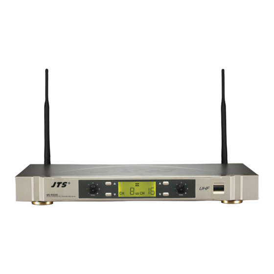
Page 9: Parts Identification & Accessories
Parts Identification & Accessories 4-1 Receiver US-902D Pro Dual Channel PLL Diversity Receiver Power Switch Channel Selector (Up/Down) LCD panel Volume control Antenna Squelch level adjustor DCV Input (12-18V DC/600mA) ∅ Unbalanced 6.3mm jack socket Balanced XLR socket Accessories Screwdriver ∅... - Page 10 US-903DC Pro Dual Channel PLL Diversity Receiver Power Switch Channel Selector (Up/Down/Set) LCD panel Volume control Antenna Charger Squelch level adjustor DCV Input (12-18V DC/1000mA) ∅ Unbalanced 6.3mm jack socket Balanced XLR socket Accessories Screwdriver ∅ AF output cable (With unbalanced 6.3 plug) AC/DC adaptor DUAL CHANNEL PLL DIVERSITY WIRELESS SYSTEM...
-
Page 11: Handheld Transmi Er
4-2 Handheld Transmitter Mh-8800(Mh-8800G) Handheld Transmitter Interchangeable capsule module LCD display Down bu on Up bu on Set bu on Ba ery tray Power On/O switch Mute On/O switch Mh-8016(Mh-8064) Handheld Transmitter Interchangeable capsule module Power On/O switch Channel Selection Gain Level Group Se ing Ba ery tray... -
Page 12: Body-Pack Transmi Er
4-3 Body-pack Transmitter PT-920B(PT-920BG) Mic. input (4 pin mini XLR socket) Power On/O switch Antenna LCD display Up bu on Down bu on Gain adjust Ba ery tray cover Screwdriver Carry case Ba ery tray Set bu on Belt-loop PT-920Bmi(PT-920BGmi) Mic. -
Page 13: Condenser Microphones
4-4 Condenser Microphones CM-501 Lavaliere Microphone Clip CM-201 Mini XLR Windscreen CM-125 Headset Microphone CM-204U Gooseneck CM-204 Headband 4 Pin Mini XLR Windscreen CM-225 CX-504 Instrument Microphone Gooseneck Clip 4 Pin Mini XLR Windscreen CX-508W CX-516W... - Page 14 Ear-hook Microphone Boom Adjustable Handband Adjustable ear hook 4 Pin Mini XLR Cable clip Windscreen Detachable Cable CM-804 CM-802 CM-825 CM-815 DUAL CHANNEL PLL DIVERSITY WIRELESS SYSTEM...
-
Page 15: Preparing Procedures & Basic Operation
Preparing procedures & basic operation 5-1Receiver (2) Audio Output Connector Connect one end of the AF output cable to the AF output socket in the rear panel, then plug another end to the “MIC IN” input socket of a mixer or ampli er. (Step 1 of Figure 1) ∅... - Page 16 (5) LCD Panel US-902D Pro RF incoming signal level of RX1 RF incoming signal level of RX2 AF incoming signal level of RX1 AF incoming signal level of RX2 Diversity of RX1 (Antenna A or B active) Diversity of RX2 (Antenna A or B active)
- Page 17 US-903DC Pro RF incoming signal level of RX1 RF incoming signal level of RX2 AF incoming signal level of RX1 AF incoming signal level of RX2 Diversity of RX1 (Antenna A or B active) Diversity of RX2 (Antenna A or B active) Group &...
- Page 18 (6) Basic Operation US-902D Pro Selecting channel Press the Up or Down bu on till the RX1 starts ashing, and again press the Up / Down bu on to select a suitable channel from the pre-set 16 channels. Later the RX1 stop ashing, the receiver will store the channel automatically meanwhile presenting the channel number.
- Page 19 US-903DC Pro Selecting group channel: Group set up: Step 1 Press “SET” bu on two sec. till the “SETUP” show up, then “A-1” starts ashing, press the Up or Down bu on to select a suitable group from the pre-set four group of A,B,C,D. en, press “SET”...
- Page 20 Using the ba ery charge of US-903DC Pro Push the charger’ s cover and put 4 pcs of rechargeable ba eries into the ba ery tray. Please match the correct polarity (+ and -) (Figure 1), then return the cover for charging the ba eries.
-
Page 21: Handheld Transmitter
5-2 Handheld Transmitter Mh-8800/Mh-8800G (1) Ba ery Insertion Insert 2 pcs 1.5V ba eries into the ba ery tray. (Figure 3) A er pu ing into the ba ery, switch on the power switch. (Figure 4) (Figure 3) (Figure 4) (2) LCD Operation Up bu on Down bu on... - Page 22 Mh-8016/Mh-8064 (1) Ba ery Insertion Insert 2 pcs 1.5V AA ba eries into the ba ery tray. (Figure 1) A er pu ing into the ba ery, switch on the power switch. (Figure 2) (Figure 1) Mh-8016 Mh-8064 (Figure 2) (2) Channel Selecting 2.1 Mh-8016 Screw o the outer body.
-
Page 23: Body-Pack Transmi Er
5-3 Body-pack Transmitter PT-920B(PT-920BG) Body-pack transmitter 1. LCD panel Main display Ba ery indictor 2. Basic operation (1) Slide the ba ery tray cover in the direction of the arrow to open it, insert two 1.5V ba eries according the correct polarity, and return the cover (Figure 3) DOWN (Figure 3) (2) Turning the transmi er On. -
Page 24: Installation Of Condenser Microphones
5-4 Installation of Condenser Microphones 1. Lavaliere microphone A ach lavaliere microphone to a tie, lapel, where is suitable for sound pick-up. Plug the connector into input socket on the body-pack transmi er. (Figure 1) (Figure 1) 2. Headset microphone Put the headband behind your head, and x the temples on your ears as (Figure 2) shows, then adjust the gooseneck to have best miking. -
Page 25: System Operation
System operation Be sure to mute the audio signal of mixer or ampli er before turning on the receiver and transmi er. 6-1 Power on Turn AF level on the receiver completely counter-clockwise to the minimum level, and switch on the receiver. As soon as you turn power on of receiver, LCD lights on, meanwhile the RF signal and AF level indicate the transmission status, and receiver is ready for operating. -
Page 26: Recommendations
6-3 Wearing the Body-pack transmitter e carry case allows body-pack transmi er to be a ached on performer’ s belt, place the antenna towards the back of his body. e Velcro tag around the belt and x it. (Figure 1) (Figure 1) Recommendations 1. - Page 27 US-902D Pro / US-903DC Pro 59508-002-03...
Need help?
Do you have a question about the US-902D Pro and is the answer not in the manual?
Questions and answers