Table of Contents
Advertisement
Quick Links
Advertisement
Table of Contents

Related Manuals for JTS US-36G2


Summary of Contents for JTS US-36G2
- Page 1 US-36G2 / Mh-36G2 / PT-B36G2 1856 59508-043-01...
- Page 2 US-36G2 UHF PLL TRue DIversity WIRELESS SYSTEMS Instruction Manual...
- Page 3 Thank you for choosing the JTS wireless system. In order to obtain the best efficiency from the system, you are recommended to take few minutes to read this instruction manual carefully.
-
Page 4: Table Of Contents
3-1 Receiver// US-36G2 3-2 Handheld Transmitter // Mh-36G2 3-3 Body-pack Transmitter // PT-36BG2 3-4 Optional Condenser Microphone 4. Part Identification & Accessories 4-1 Receiver // US-36G2 4-2 Handheld Transmitter // Mh-36G2 4-3 Body-pack Transmitter // PT-36BG2 4-4 Optional Condenser Microphone 4-5 Accessories 5. - Page 5 1. Important Caution • Always make all connections before plugging the unit into an AC power outlet. • Do not leave the devices in a place neither with high temperature nor high humidity. • Always do not handle the power cord with wet hands ! •...
-
Page 6: Receiver// Us-36G2
3. Specification 3-1 Receiver // US-36G2 Frequency Preparation..PLL Synthesized Control Carrier Frequency Range.. 502~960 MHz S/N Ratio........> 105dB T.H.D..........<0.6%@1KHz Display..........LCD / LED Display Contents..... Frequency, Antenna A/B, Mute Display, LED Meter, Battery Fuel Gauge Controls......... Power On/Off, Frequency Up/Down, Frequency Scan, Audio Level, Lock-on Audio Output Level.... -
Page 7: Body-Pack Transmitter // Pt-36Bg2
3-3 Body-pack Transmitter // PT-36BG2 Frequency Preparation....PLL Synthesized Control Carrier Frequency Range..502~960 MHz RF Outputs........10mW / 50mW (Depend on Local Regulation) Stability..........±10KHz Frequency Deviation....±48KHz LCD Display........Frequency, Battery Fuel Gauge Controls..........Power On/Off, AF Level, Frequency Up/Down, Lock-on Mode Output connector...... - Page 8 Headset Microphone Model No....... CM-214 CM-214U CM-214UL Connector....... 801C4 4P Mini XLR 801C3 (3P Mini XLR) (4P Mini XLR) 801C4 (4P Mini XLR) 801CS (3.5 stereo plug) Option Connector... 801C3 (3P Mini XLR) 801CR 801CS (3.5 stereo plug) 801CR Frequency Response..60~15,000 Hz 30~18,000 Hz 100 ~ 18,000Hz...
- Page 9 Ear-hook Microphone Model No....... CM-801/CM-804i CM-8015/CM-825i Connector......801C4 (4P Mini XLR) 801C4 (4P Mini XLR) Option Connector... 801C3 (3P Mini XLR) 801C3 (3P Mini XLR) 801CS (3.5 stereo plug) 801CS (3.5 stereo plug) 801CR 801CR Frequency Response..60~15,000 Hz 50~18,000 Hz Polar Pattern......
-
Page 10: Receiver // Us-36G2
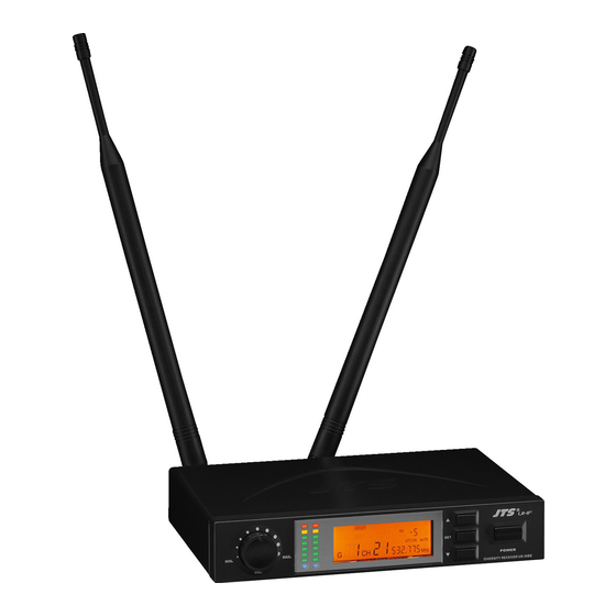
4. Parts Identification & Accessories 4-1 Receiver // US-36G2 Power On/Off switch Up button (frequency adjustment) Down button (frequency adjustment) Set button (frequency adjustment) LCD Display Volume control DC socket for connection of main unit AF output, jack socket (AF UNBAL) -
Page 11: Handheld Transmitter // Mh-36G2
4-2 Handheld Transmitter // Mh-36G2 Interchangeable capsule LCD display Down button UP button Mh-36 Set button Mh-36 Battery tray button Battery tray Power On/Off switch WIRELESS MICROPHONE SYSTEM... -
Page 12: Body-Pack Transmitter // Pt-36Bg2
4-3 Body-pack Transmitter // PT-36BG2 LCD Display Battery Tray Set button: set the configuration of bodypack transmitter Up button: select the settings of transmitter Down button: select the settings of transmitter Power Switch / Mute 4 Pin mini XLR mic. input Antenna Belt Clip LCD Panel of the Body-Pack Transmitter... -
Page 13: Optional Condenser Microphone
4-4 Optional Condenser Microphone Lavaliere Microphone // CM-501 CM-201i CM-125i Clip 4 Pin Mini XLR 3 Pin Mini XLR 3.5 Stereo Plug 4Pin Hirose connecter Windscreen CM-501 CM-201i CM-125i WIRELESS MICROPHONE SYSTEM... - Page 14 Headset Microphone // CM-214 / CM-214U / CM-214UL / CM-235 / CX-504 Gooseneck Adjustable headband Headband 4 Pin Mini XLR Windscreen CM-214 CM-214U CM-214UL Standard : 4 Pin Mini XLR 3 Pin Mini XLR 3.5 Stereo Plug CM-235 CX-504...
- Page 15 Ear-hook Microphone // CM-801 / CM-804i / CM-8015 / CM-825i Boom Adjustable Headband Adjustable ear hook Detchable Cable Cable Clip CM-801 Windscreen 4 Pin Mini XLR Option 3 Pin Mini XLR 3.5 Stereo Plug Option 4Pin Hirose connecter Option CM-804i CM-8015 CM-825i WIRELESS MICROPHONE SYSTEM...
- Page 16 Compatible Instrument Microphone // CX-500 / CX-500F / CX-520 / CX-508W / CX-516W Gooseneck Clip Bracket Volume Control Windscreen 4 Pin Mini XLR CX-500 CX-500F CX-520 CX-508W CX-516W...
- Page 17 4-5 Accessories AC/DC adaptor Switching Power Supply(100V~240V , 50~60Hz) Linear Power Supply (220V , 50Hz) Option Linear Power Supply (220V , 60Hz) Option Screwdriver DR-900 Dual Rack Adaptor Option RP-900 Panel Cover Option AF output cable (with Φ6.3 plug at both ends) GC-80/GC-100 Guitar Cable Option GC-80L/GC-100L Guitar Cable...
-
Page 18: Receiver// Us-36G2
5. Preparing Procedures & Basic Operation 5-1 Receiver // US-36G2 (1) Power output connector Plug in one end of AC/DC adaptor cable to DC input socket in the rear panel of receiver, and plug another end into an AC outlet.(Step 1) - Page 19 (3) LCD panel RF signal level AF signal level Main display LOCK ATT.ON Diversity display (A or B antenna) Battery gauge of the transmitter 60 61 Turning the receive on and off by pressing the POWER button. Press the SET button for 3 seconds to select group/frwquency scan, squelch, and output level.
- Page 20 LOCK ATT.ON MIN. MAX. VOL. DIVERSITY RECEIVER US-36G2 POWER (9) Adjusting the AF output level Use the AF output level control located on the front side of the receiver to adjustthe AF signal level that appears at output. LOCK ATT.ON...
-
Page 21: Handheld Transmitter // Mh-36G2
5-2 Handheld Transmitter // Mh-36G2 (1) Turning the transmitter on/off The on/off switch is located on the bottom of the microphone. (2) Inserting and changing the battery Figure 1 1. Loosen the microphone head counter-clockwise. (Figure 1) 2. Push both battery tray button to release it. (Figure 2) 3. - Page 22 (4) Press the SET button to select between frequency /group/ sensitivity / RF outputs. 1. Frequency adjusting Press the UP or DOWN button to adjust the setting of a menu. 1-1 Hold SET button for 3 seconds to activate frequency. 1-2 Once you see ”MHz”...
- Page 23 5-3 Body-pack Transmitter // PT-36BG2 (1) Press the SET button to select between frequency /group/ sensitivity / RF outputs. (depends on country) 1. Frequency adjusting Press the UP or DOWN button to adjust the setting of a menu. 1-1 Hold SET button for 3 seconds to activate frequency. 1-2 Once you see ”MHz”...
-
Page 24: Installation Of Condenser Microphones
Plug the connector into input socket on the body-pack transmitter. MIC IN (3) Instrument Microphones The system is compatible with JTS various instrument microphones. For detail please refer to user’ s manuals of these microphones. - Page 25 (6) Ear-hook Microphone 1. Lightweight Dual Ear Hook Microphone Try on whether the headset is fit. Adjust the headband to a suitable width. Tighten or loosen the curve of the ear-hook by twisting the loop or expanding it. Curve and bend the boom to fit your face. Attach the detachable cable to a suitable place by a cable clip.
-
Page 26: Important Notice
8. Important Notice (1) JTS offers wireless systems in a selection of bands that conform to the different government regulations of specific nations or geographic regions. These regulations help limit radio frequency (RF) interference among different wireless devices and prevent interference with local public communications channels, such as television and emergency broadcasts.
Need help?
Do you have a question about the US-36G2 and is the answer not in the manual?
Questions and answers