
Related Manuals for JTS US-902D Pro


Summary of Contents for JTS US-902D Pro
- Page 1 Instruction Manual US-902D Pro US-9216 Series US-903DC Pro US-9364 Series DUAL CHANNEL PLL DIVERSITY WIRELESS SYSTEM...
- Page 2 Thank you for choosing the JTS wireless system. In order to obtain the best efficiency from the system, you are recommended to take few minutes to read this instruction manual carefully.
-
Page 3: Table Of Contents
INDEX 1. Important Caution 2. Features 3. Specification 3-1 Overall System 3-2 Receiver 3-3 Handheld Transmitter 3-4 Body-pack Transmitter 3-5 Optional Condenser Microphone 4. Part Identification & Accessories 4-1 Receiver 4-2 Handheld Transmitter 4-3 Body-pack Transmitter 4-4 Optional Condenser Microphone 4-5 Accessories 5. - Page 4 1. Important Caution • Always makes all connections before plugging the unit into an AC power outlet. • Do not leave the device in a place neither with high temperature nor high humidity. • Always do not handle the power cord with wet hands! •...
-
Page 5: Overall System
3. Specification 3-1 Overall System RF Frequency Range....502~960 MHz Oscillation Type......PLL Synthesized Control OSC Channels........... 16 Channels (US-902D Pro / US-9216 Series) 64 Channel (US-903DC Pro / US-9364 Series) Audio Frequency Response 50~18,000Hz Band-width........24 MHz Operation Range...... -
Page 6: Handheld Transmitter
3-3 Handheld Transmitter Model No......... Mh-8800 Series /Mh-8016 Series Mh-8800G Series /Mh-8064 Series Type............Handheld Frequency Preparation.... PLL Synthesized Control Carrier Frequency Range..502~960 MHz RF Outputs........10mW Stability..........±10KHz Frequency Deviation....±48KHz LCD Display........Channel, Battery Fuel Gauge, Sensitivity Controls.......... -
Page 7: Optional Condenser Microphone
3-5 Optional Condenser Microphone Lavaliere Microphone // CM-501 CM-201 CM-125 Model No....... CM-501 CM-201 CM-125 Connector......4P Mini XLR 4P Mini XLR 4P Mini XLR Frequency Response..100~15,000 Hz 60~15,000 Hz 50~18,000 Hz Polar Pattern......Cardioid Omni-directional Omni-directional Sensitivity (at 1000Hz) -60±3 dB -60±3 dB -53±3 dB... - Page 8 Ear-hook Microphone // CM-801 CM-804i CM-8015 CM-825i Model No....... CM-801/CM-804i CM-8015/CM-825i Connector......801C3 (3 pin mini XLR) 801C3 (3 pin mini XLR) 801C4 (4 pin mini XLR) 801C4 (4 pin mini XLR) 801CS (3.5 stereo plug) 801CS (3.5 stereo plug) Frequency Response..
-
Page 9: Receiver
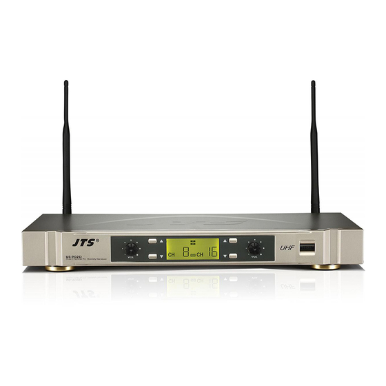
4. Parts Identification & Accessories 4-1 Receiver // US-902D Pro / US-9216 Series Dual Channel PLL Diversity Receiver Power Switch Channel Selector (Up/Down) LCD panel Volume control Antenna Squelch level adjustor DCV Input (12-18V DC/300mA) Unbalanced Ø6.3mm jack socket Balanced XLR socket... -
Page 10: Handheld Transmitter
4-2 Handheld Transmitter // Mh-8800G(i) / Mh-8800(i) Series Interchangeable dynamic capsule LCD display Down button UP button Set button Battery tray Power On/Off switch Mh-8800Gi Mh-8800G Mute On/Off switch Mh-8800Gi Mh-8800Gi Mh-8800G Mh-8800i Mh-8800 Mh-8064 / Mh-8016 Series Interchangeable dynamic capsule Power On/Off switch Channel Selector Gain Level... -
Page 11: Body-Pack Transmitter
4-3 Body-pack Transmitter // PT-920BG(mi) / PT-920B(mi) Mic. input Power On/off switch Antenna LCD display Set button Up button PT-920BG Down button AF level control Gain adjust Battery tray PT-920B PT-920BG Battery tray cover Carry case Belt-loop 4-4 Optional Condenser Microphone Lavaliere Microphone // CM-501 CM-201 CM-125 Clip 4 Pin Mini XLR... - Page 12 Headset Microphone // CM-204 CM-204U CM-204UL CM-225 CX-504 Gooseneck Headband 4 Pin Mini XLR Windscreen CM-204 CM-204U CM-204UL CM-225 CX-504 WIRELESS MICROPHONE SYSTEM...
- Page 13 Ear-hook Microphone // CM-801 CM-804i CM-8015 CM-825i Boom CM-801 Adjustable Headband Adjustable ear hook Detchable Cable Cable Clip Windscreen 4 Pin Mini XLR 3 Pin Mini XLR CM-804i 3.5 Stereo Plug CM-8015 CM-825i Instrument Microphone // CX-508W CX-516W Gooseneck Clip Windscreen 4 Pin Mini XLR CX-508W...
-
Page 14: Accessories
4-5 Accessories AC/DC adaptor Switching Power Supply(100V~240V , 50~60Hz) Linear Power Supply (220V , 50Hz) Linear Power Supply (220V , 60Hz) Screwdriver RM-12 Rack mount kit Option AF output cable (with Ø6.3 plug at both ends) GC-80/GC-100 Guitar Cable Option GC-80L/GC-100L Guitar Cable Option WIRELESS MICROPHONE SYSTEM... -
Page 15: Receiver
5. Preparing Procedures & Basic Operation 5-1 Receiver (1) Audio Output Connector Connect one end of the AF output cable to the AF output socket in the rear panel, then plug another end to the “MIC IN” input socket of a mixer or amplifier. (Step 1) It is equipped with balanced XLR output and unbalanced Φ6.3mm output, choose the proper way for use. - Page 16 (5) LCD Panel US-902D Pro / US-9216 Series RF incoming signal level of RX1 RF incoming signal level of RX2 AF incoming signal level of RX1 AF incoming signal level of RX2 Diversity of RX1 (Antenna A or B active)
- Page 17 (6) Basic Operation US-902D Pro / US-9216 Series 1. Selecting channel Press the Up or Down button till the RX1 starts flashing, and again press the Up / Down button to select a suitable channel from the pre-set 16 channels. Later the RX1 stop flashing, the receiver will store the channel automatically meanwhile presenting the channel number.
- Page 18 US-903DC Pro / US-9364 Series 1. Selecting group channel: Step 1 Group set up: Press “SET” button two sec. till the “ ” show up, then “A-1” starts flashing, press the Up or Down button to select a suitable group from the pre-set four group of “...
- Page 19 Using the battery charger of US-903DC Pro / US-9364 Series(Optional) 1. Push the charger’ s tray and put 4 pcs of rechargeable batteries into the battery tray. Please match the correct polarity (+ and -) , then return the tray for charging the batteries. 2.
-
Page 20: Handheld Transmitter
5-2 Handheld Transmitter // Mh-8800G(i) / Mh-8800(i) Series (1) Battery Insertion 1. Insert 2 pcs 1.5V batteries into the battery tray. 2. After putting into the battery, switch on the power switch. Mh-8800Gi Mh-8800Gi Mh-8800G (2) LCD Operation Down button Battery tray Up button Set button... - Page 21 Mh-8064 / Mh-8016 Series (1) Battery Insertion 1. Insert 2 pcs 1.5V AA batteries into the battery tray. 2. After install batteries, switch on the power switch. Power Power Battery tray Mh-8064 Mh-8016 Series Series (2) Channel Selecting 1. Mh-8016 Series 1-1 Screw off the outer body.
-
Page 22: Body-Pack Transmitter
5-3 Body-pack Transmitter // PT-920BG(mi) / PT-920B(mi) (1) LCD panel Main display Battery indictor (2) Basic operation 1. Slide the battery tray cover in the direction of the arrow to open it, insert two 1.5V batteries according the correct polarity, and return the cover. -
Page 23: Installation Of Condenser Microphones
5-4 Installation of Condenser Microphones (1) Lavaliere microphone Attach lavaliere microphone to a tie, lapel, where is suitable for sound pick-up. Plug the connector into input socket on the body-pack transmitter. PT-920BG (2) Headset microphone Put the headband behind your head, and fix the temples on your ears as shows, then adjust the gooseneck to have best miking. - Page 24 (4) Ear-hook Microphone 1. Lightweight Dual Ear Hook Microphone Try on whether the headset is fit. Adjust the headband to a suitable width. Tighten or loosen the curve of the ear-hook by twisting the loop or expanding it. Curve and bend the boom to fit your face. Attach the detachable cable to a suitable place by a cable clip.
- Page 25 6. System Operation Be sure to mute the audio signal of mixer or amplifier before turning on the receiver and transmitter. 6-1 Power on Turn AF level on the receiver completely counter-clockwise to the minimum level, and switch on the receiver. As soon as you turn power on of receiver, LCD lights on, meanwhile the RF signal and AF level indicate the transmission status, and receiver is ready for operating.
- Page 26 7. Recommendation (1) In order to achieve the optimum reception condition and also extend the operating distance, please leave a “open space” between the receiver and transmitter. (2) Keep the devices away from the metal objects or any interference sources, at least 50 cm. (3) To avoid the feed-back effect, don’t leave the mic.
- Page 27 8. Important notice (1) JTS offers wireless systems in a selection of bands that conform to the different government regulations of specific nations or geographic regions. These regulations help limit radio frequency (RF) interference among different wireless devices and prevent interference with local public communications channels, such as television and emergency broadcasts.
- Page 28 US-902D Pro / US-903DC Pro US-9216 Series / US-9364 Series 1856 59508-002-07...
Need help?
Do you have a question about the US-902D Pro and is the answer not in the manual?
Questions and answers