Sign In
Upload
Download
Add to my manuals
Delete from my manuals
Share
URL of this page:
HTML Link:
Bookmark this page
Add
Manual will be automatically added to "My Manuals"
Print this page
×
Bookmark added
×
Added to my manuals
Manuals
Brands
JTS Manuals
Microphone system
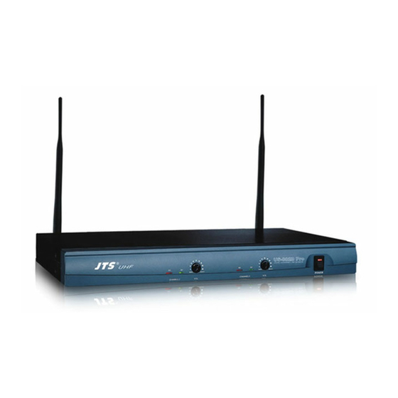
US-802D Pro
Instruction manual
JTS US-802D Pro Instruction Manual
Dual channel diversity wireless system
Hide thumbs
1
2
3
Table Of Contents
4
5
6
7
8
9
10
11
12
13
14
15
16
17
18
19
20
21
22
23
24
25
26
27
28
page
of
28
Go
/
28
Contents
Table of Contents
Bookmarks
Advertisement
Quick Links
1
Table of Contents
2
Receiver
3
Handheld Transmitter
4
Receiver
5
Body-Pack Transmitter
6
Receiver
Download this manual
US-802D Pro / US-822D Pro / US-852D Pro / US-882D Pro
Mh-900 / Mh-910 / Mh-700 / Mh-800 / Mh8000(i) / Mh-D8 / Mh-860 / PT-900B
59506-049-08
Table of
Contents
Previous
Page
Next
Page
1
2
3
4
5
Advertisement
Need help?
Do you have a question about the US-802D Pro and is the answer not in the manual?
Ask a question
Questions and answers
Related Manuals for JTS US-802D Pro
Microphone system JTS US-8010D Instruction Manual
Us-8010d series (12 pages)
Microphone system JTS US-936K Instruction Manual
Dual channel wide bandwindth wireless system (9 pages)
Microphone system JTS US-901D Instruction Manual
Uhf pll wireless systems (28 pages)
Microphone system JTS US-9001D Instruction Manual
(16 pages)
Microphone system JTS US-36G2 Instruction Manual
Uhf pll true diversity wireless systems (28 pages)
Microphone system JTS US-36G2 Instruction Manual
True diversity (32 pages)
Microphone system JTS US-902D Pro Instruction Manual
Dual channel pll diversity wireless system (29 pages)
Microphone system JTS US-902D Pro Instruction Manual
Dual channel pll diversity wireless system (27 pages)
Microphone system JTS US-1000D-TH Instruction Manual
Uhf pll wireless systems (10 pages)
Microphone system JTS US-9020D Pro Instruction Manual
Dual channel pll diversity wireless system (26 pages)
Microphone system JTS US-8001D Instruction Manual
Us-8216d series (12 pages)
Microphone system JTS US-8216D Series Instruction Manual
(25 pages)
Microphone system JTS US-8001D Instruction Manual
Single/dual channel pll diversity wireless system (24 pages)
Microphone system JTS US-902D Instruction Manual
Dual channel pll diversity wireless system (31 pages)
Microphone system JTS MONACOR US-8001DB/5 Instruction Manual
Uhf audio transmission system (21 pages)
Microphone system JTS UF-10R Product Manual
Professional wideband 60-75mhz true diversity system (48 pages)
This manual is also suitable for:
Us-822d pro
Us-852d pro
Us-882d pro
Mh-900
Mh-910
Mh-700
...
Show all
Mh-800
Mh8000i
Mh-d8
Mh-860
Pt-900b
Mh8000
Print
Rename the bookmark
Delete bookmark?
Delete from my manuals?
Login
Sign In
OR
Sign in with Facebook
Sign in with Google
Upload manual
Upload from disk
Upload from URL


Need help?
Do you have a question about the US-802D Pro and is the answer not in the manual?
Questions and answers