JTS US-8001D Instruction Manual
Single/dual channel pll diversity wireless system
Hide thumbs
Also See for US-8001D:
- Instruction manual (7 pages) ,
- Instruction manual (12 pages) ,
- Instruction manual (25 pages)

Related Manuals for JTS US-8001D


Summary of Contents for JTS US-8001D
- Page 1 US-8001D Instruction Manual US-8002D SINGLE / DUAL CHANNEL PLL DIVERSITY WIRELESS SYSTEM...
- Page 2 JTS wireless system. In order to obtain the best e ciency from the system, you are recommended to read this instruction manual carefully.
-
Page 3: Table Of Contents
TABLE CONTENTS 1. Important Cautions 2. Features 3. Specification 3-1 Overall System 3-2 Receiver 3-3 Transmi er 3-4 Optional Condenser Microphone 4. Parts Identification & Accessories 4-1 Receiver 4-2 Handheld Transmi er 4-3 Body-pack Transmi er 4-4 Condenser Microphones 4-5 Optional Accessories 5. -
Page 4: Important Cautions
Important Cautions Always makes all connections before plugging the unit into an AC power outlet. Do not leave the device in a place neither with high temperature nor high humidity. Always do not handle the power cord with wet hands! Keep the devices away from re and heat sources. -
Page 5: Specification
Channels 16 Channels Audio Frequency Response 50 Hz~18KHz Band-width 24 Mhz Operation Range 100M 3-2 Receiver Receiving Mode US-8001D US-8002D Frequency Stability ±0.005% ±0.005% S/N Ratio >100 dB >100 dB RF Sensitivity -107dBm (12DB S/N AD) -107dBm (12DB S/N AD) Image Rejection >60 dB... -
Page 6: Transmi Er
3-3 Transmitter Model No. Mh-850 / Mh-8016 Mh-750 Type Handheld Handheld Ball Grille Shape Flat top Round top Spurious Rejection <-60dBc <-60dBc Stability ±10KHz ±10KHz Frequency Deviation ±48 KHz ±48 KHz S/N Ratio >100 dB (1 KHz-A) >100 dB (1 KHz-A) Current Consumption 100 mA 100 mA... -
Page 7: Optional Condenser Microphone
3-4 Optional Condenser Microphone Lavaliere Microphone Model No. CM-501 CX-201 CM-125 Frequency Range 100Hz~15,000Hz 60Hz~15,000Hz 50Hz~18,000Hz Polar Pa ern Cardioid Omini-directional Omini-directional Sensitivity @ 1 KHz -60dB±3dB -60dB±3dB -53dB±3dB Impedance 2.2k±30% 2.2k±30% 4.4k±30% max. SPL for 1% T.H.D. 130dB 130dB 130dB Connector Type 4 Pin Mini XLR... - Page 8 Ear-hook Microphone Model No. CM-802/CM-804 CM-815/CM-825 Frequency Response 60 ~ 15,000Hz 50 ~ 18,000Hz Polar Pa ern Omni-directional Omni-directional Sensitivity (at 1KHz) -66±3 dB* (0.5mV)*0dB -53±3 dB* (2.24mV)*0dB Impedance =1V/ bar,1KHz =1V/ bar,1KHz Rated impedance 2.2k Rated impedance 4.4k Max. SPL for 1% THD 130dB 130dB Connector...
-
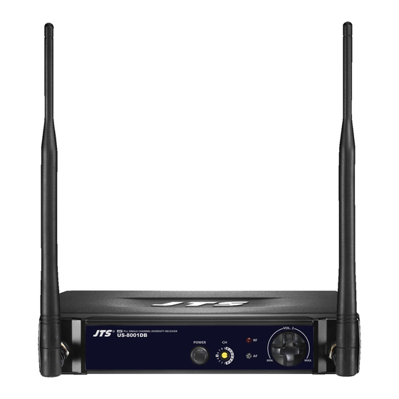
Page 9: Parts Identification & Accessories
Parts Identification & Accessories 4-1 Receiver US-8001D Single Channel PLL Diversity Receiver Power On Channel Selector RF indicator AF indicator Volume control Antenna DCV Input (12-18V DC/600mA) Unbalanced 6.3mm jack socket Balanced XLR socket Accessories ∅ AF output cable (With unbalanced 6.3 plug) - Page 10 US-8002D Dual Channel PLL Diversity Receiver Power On Channel Selector RF indicator AF indicator Volume control Antenna DCV Input (12-18V DC/600mA) ∅ Unbalanced 6.3mm jack socket Balanced XLR socket Accessories AF output cable (With unbalanced 6.3 plug) AC/DC adaptor Scerwdriver DUAL CHANNEL PLL DIVERSITY WIRELESS SYSTEM...
-
Page 11: Handheld Transmi Er
4-2 Handheld Transmitter Mh-850 Handheld Transmitter Interchangeable capsule module Ba ery tray release knobs Ba ery tray Channel selector Power On/O switch LED Indicator ID housing Mh-750 Handheld Transmitter Interchangeable capsule module Ba ery tray release knobs Ba ery tray Channel selector Power On/O switch LED Indicator... -
Page 12: Body-Pack Transmi Er
Mh-8016 Handheld Transmitter Interchangeable capsule module Power On/O switch Channel selector Gain control Ba ery tray 4-3 Body-pack Transmitter PT-850B Mic. input (mini 4 pin XLR socket) Power On/O switch Antenna LED indiccator for power and ba ery status Ba ery tray AF leavel control Carry case Belt-loop... -
Page 13: Condenser Microphones
PT-850Bmi Mic. input (mini 4 pin XLR socket) Power On/O switch Antenna LED indiccator for power and ba ery status Ba ery tray AF leavel control Carry case Belt-loop Channel selector A enuation Pad 4-4 Condenser Microphones Lavaliere Microphone Clip 4 Pin Mini XLR Windscreen CM-501... - Page 14 Headset Microphone Gooseneck Headband 4 Pin Mini XLR Windscreen CM-204U CM-204 CM-225 CX-504 Instrument Microphone Gooseneck Clip 4 Pin Mini XLR Windscreen CX-508W CX-516W DUAL CHANNEL PLL DIVERSITY WIRELESS SYSTEM...
-
Page 15: Optional Accessories
Ear-hook Microphone Boom Adjustable Handband Adjustable ear hook 4 Pin Mini XLR Cable clip Windscreen Detachable Cable CM-804 CM-802 CM-825 CM-815 4-5 Optional Accessories DR-900 Dual Rack Adaptor RP-900 Panel Cover... -
Page 16: Preparing Procedures & Basic Operation
Preparing procedures & basic operation 5-1 Receiver (1) Audio Output Connector ∅ e receiver equipped with both balanced XLR output and unbalanced 6.3mm jack output; you can choose the proper way for using. Connect one end of the AF output cable to the AF output socket in the rear panel of receiver and plug another end to the “MIC IN”... -
Page 17: Ba Ery Insertion Of The Transmi Er
5-2 Battery Insertion of the transmitter (1) Mh-850 & Mh-750 Handheld Transmi er 1. Turn the microphone ball grille counter-clockwise (Step 1 of Figure 2), press both release knobs to remove the ba ery tray from the mic. housing (Step 2 of Figure 2). - Page 18 (2) Mh-8016 Handheld Transmi er Insert 2 pcs 1.5V AA ba eries into the ba ery tray. (Figure 1) A er pu ing into the ba ery, switch on the power switch. (Figure 2) (Figure 1) (Figure 2) (3) PT-850B / PT-850Bmi Body-pack Transmi er Slide the ba ery tray cover in the direction of the arrow to open it.
-
Page 19: Rack Mounting
5-3 Rack Mounting (1) Before mount receivers onto DR-900 rack adaptor, please release any cables from the rear of the receiver. (2) Turn over receiver and DR-900 rack adaptor simultaneously, there are 4 threaded holes each in the bo om of receiver and rack adaptor for inserting screws. (3) Single receiver Insert in a receiver through the front of DR-900 until it is rmly a ached to the rack, then screw on a RP-900 to another side of the rack. -
Page 20: Installation Of Condenser Microphones
5-4 Installation of condenser microphones (1) Lavalier microphone A ach a laveliere microphone to , tie, lapel, where is suitable for sound pick-up. Plug the connector into input socket on the body-pack transmi er. (Figure 1) (Figure 1) (2) Headset microphone Put the headband behind your head, and x the temples on your ears as (Figure 2) shows, then adjust the gooseneck to have best miking. -
Page 21: System Operation
System operation Be sure to mute the audio signal of a mixer or ampli er before turning on the receiver and transmi er. (1) Power on Turn AF level on the receiver completely counter-clockwise to the minimum level, and switch on the receiver. As soon as you turn power of the receiver on, the power LED lights red, meanwhile the RF signal and AF LED light up to indicate the receiver is ready for operating. - Page 22 (3) Using the PT-850B / PT-850Bmi Body-pack transmi er 1. Use the supplied screwdriver to adjust the gain control on the rear panel of PT-850B / PT-850Bmi body-pack transmi er to a proper level. (Figure 1) (Figure 1) e carry case allows the PT-850B to be a ached on performer’ s belt, place the antenna towards the back of his body.
-
Page 23: Recommendations
Recommendation 1. In order to achieve the optimum reception condition and also extend the operating distance, please leave on “open space” between the receiver and transmi er. 2. Keep the devices away from the metal objects or any interference sources at least 50 cm. - Page 24 US-8001D / US-8002D 59506-036-03...
Need help?
Do you have a question about the US-8001D and is the answer not in the manual?
Questions and answers