Table of Contents
Advertisement
Quick Links
Panel PC 900
User's Manual
Version: 1.05 (April 2014)
Model no.: MAPPC900-ENG
All information contained in this manual is current as of its creation/publication. B&R reserves the right to change
the contents of this manual without notice. The information contained herein is believed to be accurate as of
the date of publication; however, Bernecker + Rainer Industrie-Elektronik Ges.m.b.H. makes no warranty, ex-
pressed or implied, with regard to the products or documentation contained within this manual. In addition,
Bernecker + Rainer Industrie-Elektronik Ges.m.b.H. shall not be liable for any incidental or consequential damages
in connection with or arising from the furnishing, performance or use of the product(s) in this documentation. Soft-
ware names, hardware names and trademarks are registered by their respective companies.
1
Advertisement
Table of Contents

Related Manuals for B&R Industries MAPPC900-ENG


Summary of Contents for B&R Industries MAPPC900-ENG
- Page 1 User's Manual Version: 1.05 (April 2014) Model no.: MAPPC900-ENG All information contained in this manual is current as of its creation/publication. B&R reserves the right to change the contents of this manual without notice. The information contained herein is believed to be accurate as of the date of publication;...
- Page 2 Chapter 1: General information Chapter 2: Technical data Chapter 3: Installation Chapter 4: Software Chapter 5: Standards and certifications Chapter 6: Accessories Chapter 7: Maintenance and service Appendix A...
-
Page 3: Table Of Contents
Table of contents Chapter 1 General information................... 9 1 Manual history..............................9 2 Safety guidelines..............................10 2.1 Intended use...............................10 2.2 Protection against electrostatic discharge....................10 2.2.1 Packaging..............................10 2.2.2 Guidelines for proper ESD handling.....................10 2.3 Policies and procedures..........................10 2.4 Transport and storage..........................11 2.5 Installation..............................11 2.6 Operation.............................. - Page 4 Table of contents 2.4.11 Status LEDs............................48 2.4.12 Power button............................49 2.4.13 Reset button............................49 2.4.14 Battery..............................50 2.4.15 Slide-in compact slot...........................51 2.4.16 Slide-in slot............................51 2.4.17 Main memory............................52 2.4.18 IF option 1 slot............................53 2.4.19 IF option 2 slot............................53 2.4.20 Card slot (PCI / PCIe)........................54 2.5 Serial number sticker..........................55 3 Individual components.............................
- Page 5 Table of contents 3.10.6 5CAUPS.xxxx-01..........................129 3.11 Power supply............................131 3.11.1 5AC902.PS00-00..........................131 Chapter 3 Installation....................132 1 Installation..............................132 1.1 Installation Panel PC 900.........................132 1.2 Installation information for individual components................... 134 1.3 Replacing the CPU board and system unit..................... 135 1.4 Installing or replacing the AC power supply.................... 137 1.5 Replacing the main memory modules......................139 1.6 Installing the interface option........................
- Page 6 Table of contents 1.4.4 PCI Express configuration........................196 1.4.5 ACPI settings............................202 1.4.6 RTC wake settings..........................203 1.4.7 CPU configuration..........................204 1.4.8 Chipset configuration.......................... 207 1.4.9 SATA configuration..........................208 1.4.10 Memory configuration........................211 1.4.11 USB configuration..........................214 1.4.12 Serial port console redirection......................218 1.5 Boot................................220 1.5.1 Boot device priority..........................
- Page 7 Table of contents 5.4 Installation..............................245 5.5 Drivers...............................246 6 Windows Embedded Standard 2009......................247 6.1 General information..........................247 6.2 Order data..............................247 6.3 Overview..............................247 6.4 Features with WES2009 (Windows Embedded Standard 2009)............. 247 6.5 Installation..............................248 6.6 Drivers...............................248 7 Automation Runtime............................249 7.1 General information..........................
- Page 8 Table of contents 5.2.1 5CASDL.0xxx-00..........................264 5.3 SDL cables with 45° male connector.......................267 5.3.1 5CASDL.0xxx-01..........................267 5.4 SDL flex cables............................270 5.4.1 5CASDL.0xxx-03..........................270 5.5 SDL flex cables with extender......................... 273 5.5.1 5CASDL.0xx0-13..........................273 5.6 USB cables...............................277 5.6.1 5CAUSB.00xx-00..........................277 5.7 RS232 cables............................278 5.7.1 9A0014.xx............................
-
Page 9: Chapter 1 General Information
General information • Manual history Chapter 1 • General information 1 Manual history Version Date Change 1.00 19-Dec-13 First version • 1.05 2014-04-16 Updated section "Maximum ambient temperature during operation" on page 27. • Updated vibration and shock specifications of the complete system for storage and transport, see page •... -
Page 10: Safety Guidelines
General information • Safety guidelines 2 Safety guidelines 2.1 Intended use Programmable logic controllers (PLCs), operating/monitoring devices (industrial PCs, Power Panels, Mobile Pan- els, etc.), and B&R uninterruptible power supplies have been designed, developed and manufactured for conven- tional use in industrial environments. They were not designed, developed and manufactured for any use involving serious risks or hazards that could lead to death, injury, serious physical damage or loss of any kind without the implementation of exceptionally stringent safety precautions. -
Page 11: Transport And Storage
General information • Safety guidelines When using programmable logic controllers or operating/monitoring devices as control systems together with a Soft PLC (e.g. B&R Automation Runtime or comparable product) or Slot PLC (e.g. B&R LS251 or comparable product), safety precautions relevant to industrial control systems (e.g. the provision of safety devices such as emergency stop circuits, etc.) must be observed in accordance with applicable national and international regulations. -
Page 12: Environmentally Friendly Disposal
General information • Safety guidelines 2.7 Environmentally friendly disposal All B&R programmable controllers, operating/monitoring devices and uninterruptible power supplies are designed to inflict as little harm as possible on the environment. 2.7.1 Separation of materials It is necessary to separate different materials so the device can undergo an environmentally friendly recycling process. -
Page 13: Organization Of Safety Notices
General information • Guidelines 3 Organization of safety notices Safety notices in this manual are organized as follows: Safety notice Description Danger! Disregarding these safety guidelines and notices can be life-threatening. Warning! Disregarding these safety guidelines and notices can result in severe injury or substantial damage to equipment. Caution! Disregarding these safety guidelines and notices can result in injury or damage to equipment. -
Page 14: Overview
General information • Overview 5 Overview Product ID Short description on page Automation Runtime 1A4600.10-5 B&R Automation Runtime ARwin, including license sticker 1A4601.06-5 B&R Automation Runtime ARemb, including license sticker Batteries 0AC201.91 Lithium batteries 4 pcs., 3 V / 950 mAh button cell We hereby state that the lithium cells contained in this shipment qualify as "partly regulated". - Page 15 General information • Overview Product ID Short description on page Main memory 5MMDDR.1024-03 SO-DIMM DDR3, 1024 MB 5MMDDR.2048-03 SO-DIMM DDR3, 2048 MB 5MMDDR.4096-03 SO-DIMM DDR3, 4096 MB 5MMDDR.8192-03 SO-DIMM DDR3, 8192 MB Power supply 5AC902.PS00-00 PPC900 power supply 85-264 VAC RS232 cable 9A0014.02 RS232 extension cable for remote operation of a display unit with touch screen, 1.8 m...
- Page 16 General information • Overview Product ID Short description on page 5SWWXP.0600-MUL Microsoft OEM Windows XP Professional Service Pack 3, CD, multilingual. Only available with a new device. Panel PC 900 User's Manual V1.05...
-
Page 17: Chapter 2 Technical Data
Technical data • Introduction Chapter 2 • Technical data 1 Introduction 1.1 About this user's manual This user's manual contains all relevant information about a functioning Panel PC 900. 1.2 Description of individual modules 1.2.1 Display units Display units consists of a display and touch screen and form the basis for each Automation Panel 9x3 and Panel PC 900 System. -
Page 18: Structure/Configuration
Technical data • Introduction 1.3 Structure/Configuration Automation Panel 9x3 and Panel PC900 systems can be assembled to meet individual requirements and operating conditions. Automation Panel 9x3 and Panel PC 900 systems are so flexible that an Automation Panel can be rebuilt into a Panel PC and a Panel PC into an Automation Panel. - Page 19 Technical data • Introduction Accessory and software configuration Power supply Select 1 5AC902.PS00-00 Slide-in compact drives Select 1 5AC901.CHDD-01 5AC901.CSSD-05 5AC901.CSSD-03 5AC901.CCFA-00 5AC901.CSSD-04 IF options Select max. 2 5AC901.I485-00 5AC901.IHDA-00 5AC901.IRDY-00 5AC901.ICAN-00 5AC901.ISRM-00 Select 1 each UPS module Battery unit UPS cable 5AC901.IUPS-00 + 5AC901.BUPS-00 5CAUPS.0005-01...
-
Page 20: Configuration Options
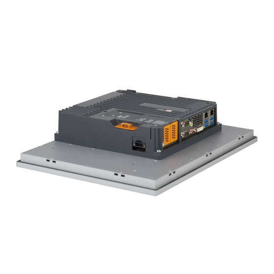
Technical data • Introduction Configuration options Panel PC 900 Panel PC 900 with power supply Figure 3: Panel PC 900 without bus unit Panel PC 900 with 1-slot bus unit Panel PC 900 with 1-slot bus unit and power supply Figure 4: Panel PC 900 with 1-slot bus unit Panel PC 900 with 2-slot bus unit Panel PC 900 with 2-slot bus unit and power supply... -
Page 21: Complete System
Technical data • Complete system 2 Complete system 2.1 Mechanical characteristics 2.1.1 Dimensions Figure 6: Panel PC 900 + power supply + bus units - Dimensions All dimensions are specified in mm. Display type Model number 12" single-touch 5AP923.1215-00 13.5 15"... -
Page 22: Installation Diagrams
Technical data • Complete system 2.1.2 Installation diagrams Information: When installing the Panel PC 900, spacing for air circulation as well as additional clearance for device operation and maintenance must be taken into consideration. Figure 7: Panel PC 900 + power supply + bus units - Installation diagram All dimensions are specified in mm. -
Page 23: Spacing For Air Circulation
Technical data • Complete system 2.1.3 Spacing for air circulation In order to guarantee sufficient air circulation, the specified amount of space above, below, to the side and behind the device must be provided. The minimum specified spacing is indicated in the following diagram. This applies to all variants. -
Page 24: Mounting Orientations
Technical data • Complete system 2.1.4 Mounting orientations The following diagrams show the approved mounting orientations for the Panel PC 900. The PPC900 must be mounted as described in the following sections. 0° 0° Figure 9: Panel PC 900 - Mounting orientation Mounting orientation Ambient temperature limitation 0°... -
Page 25: Weight Specifications
Technical data • Complete system 2.1.5 Weight specifications All weights are specified in g (grams). Display type Model number Weight 12" single-touch 5AP923.1215-00 2200 15" single-touch 5AP923.1505-00 3700 19" single-touch 5AP923.1906-00 5800 15" widescreen multi-touch 5AP933.156B-00 3850 18" widescreen multi-touch 5AP933.185B-00 4850 21"... -
Page 26: Environmental Characteristics
Technical data • Complete system 2.2 Environmental characteristics 2.2.1 Temperature specifications CPU boards can be combined with various other components such as drives, main memory, additional plug-in cards, etc. depending on the display unit and system unit. The many different configurations possible result in varying maximum ambient temperatures, which can be seen in the following tables in this section. -
Page 27: Maximum Ambient Temperature During Operation
Technical data • Complete system 2.2.1.1 Maximum ambient temperature during operation Operation with a fan kit Information: The 5PC911.SX00-00 system unit must be used when operating the Panel PC 900 with a fan kit. Operation with a fan kit and 5PC911.SX00-00 system unit 3615QE 3612QE 3555LE... - Page 28 Technical data • Complete system Operation without a fan kit Information: The 5PC901.TS77-00 CPU board cannot be operated without a fan kit. The 5PC911.SX00-01 system unit must be used when operating the Panel PC 900 without a fan kit. Operation without a fan kit and 5PC911.SX00-01 system unit 3615QE 3612QE 3555LE...
- Page 29 Technical data • Complete system 5. The mounting orientation of the Panel PC 900 may result in limitations. For more information, see "Mounting orientations" on page 24. If there is a "✓" next to the component, it can be used at the maximum ambient temperature of the complete system without problems.
-
Page 30: Temperature Sensor Positions
Technical data • Complete system 2.2.1.5 Temperature sensor positions Sensors indicate temperature values at many different locations in the PPC900. The temperatures can be read in BIOS (Advanced - OEM features - System board features / CPU board features - Temperature values) or in Microsoft Windows operating systems via the B&R Control Center For applications that don't use Windows, the temperatures can be evaluated using the B&R implementation guide. -
Page 31: Fan Control
Technical data • Complete system 2.2.1.6 Fan control The MTCX constantly monitors the temperature using temperature sensors, which directly determines how the fans are controlled. The speed depends on the measured temperature. Limit values may depend on the MTCX firmware version being used. Position Measurement point... -
Page 32: Humidity
Technical data • Complete system 2.2.2 Humidity The following table lists the minimum and maximum relative humidity values for the individual components that are relevant for the humidity limitations of a complete system. The lowest and highest common values are always used when establishing these limits. -
Page 33: Vibration
Technical data • Complete system 2.2.3 Vibration The following table provides an overview of the maximum vibration specifications of the complete system. The use of individual components may result in limitations. Panel PC Operation Storage Transport Continuous Periodic With SSD drives and CFast cards 9 to 200 Hz: 1 g 9 to 200 Hz: 1 g 2 to 8 Hz: 7.5 mm amplitude... -
Page 34: Electrical Characteristics
Technical data • Complete system 2.3 Electrical characteristics 2.3.1 +24 VDC power supply The 3-pin male connector required for the supply voltage connection is not included in delivery. It can be ordered from B&R using model number 0TB103.9 (screw clamp) or 0TB103.91 (cage clamp). The pinout is listed in the following table. -
Page 35: Power Calculation
Technical data • Complete system 2.3.3 Power calculation In order to calculate the total power of the Panel PC, the power specifications of the display being used (see "Display units - Power calculation") must be entered in the "Display unit, permanent consumer" row of the "CPU board - Power calculation"... - Page 36 Technical data • Complete system In order to accurately determine the total power of the complete system, the values in this table must be entered in the power calculation table depending on the display unit being used. Display type Model number +5 V +12 V 12"...
-
Page 37: Block Diagram
Technical data • Complete system 2.3.4 Block diagram The following block diagram shows the simplified structure of the Panel PC 900 complete system without a display unit. Socket 1 / 2 Bus units 5AC902.BX01-00 5AC902.BX01-01 5AC902.BX02-00 5AC902.BX01-01 Battery IF Option 1 IF Option 2 SRAM RS232/422/485... -
Page 38: Device Interfaces And Slots
Technical data • Complete system 2.4 Device interfaces and slots 2.4.1 Overview of device interfaces Interfaces are located on the bottom of the Panel PC 900. The following indicates the position of interfaces on a Panel PC 900 with installed bus unit and AC power supply. (20) (19) (18) - Page 39 Technical data • Complete system (30) (29) (31) (21) (25) (23) (26) (22) (27) (24) (28) Figure 13: Device interfaces - Overview (side) No. Type of interface No. Type of interface 21 CFast "CFast slot" 27 LINK LED "Status LEDs" 22 Main memory and "Main memory"...
-
Page 40: Supply Voltage
Technical data • Complete system 2.4.2 Supply voltage The Panel PC can be operated with 24 VDC or optionally with 100~240 VAC. The 5AC902.PS00-00 power supply is needed for AC power. Information on installing or exchanging the power supply can be found under "Installing or replacing the AC power supply"... - Page 41 Technical data • Complete system 2.4.2.2 Optional Supply voltage VAC In order to operate the Panel PC with AC power, the optional 5AC902.PS00-00 power supply must be installed on the Panel PC. The 3-pin male connector required for the supply voltage connection is not included in delivery. This can be ordered from B&R using model number 0TB3103.8000.
-
Page 42: Com1 Serial Interface
Technical data • Complete system 2.4.3 COM1 serial interface COM1 serial interface RS232 Type RS232, modem-capable, not electrically isolated UART 16550-compatible, 16-byte FIFO Transfer rate Max. 115 kbit/s Bus length Max. 15 m 9-pin male DSUB connector Assignment Table 29: COM1 - Pinout The interfaces, etc. -
Page 43: Monitor/Panel Interface
Technical data • Complete system 2.4.5 Monitor/Panel interface Monitor/Panel interface - RGB / SDL (Smart Display Link) / DVI The following is an overview of the video signals available on the monitor/panel output. For details, see the technical data for the CPU board being used. CPU board Video signals for all system unit variants 5PC901.TS77-00... - Page 44 Technical data • Complete system Pin Assignment Description Pin Assignment Description Analog ground (return for R, 14 +5 V power +5 V power supply C5 ANALOG GND G and B signals) Ground (return for +5 V, HSync Ground and VSync) Table 32: DVI interface - Pinout Protected internally by a multifuse.
-
Page 45: Ethernet 1 (Eth1)
Technical data • Complete system 2.4.6 Ethernet 1 (ETH1) This Ethernet controller is integrated in the CPU board and connected to external devices via the system unit. Ethernet 1 interface (ETH1 Controller Intel® 82579V RJ45 twisted pair (10BaseT/100BaseT), female Cabling S/STP (Cat 5e) Transfer rate 10/100/1000 Mbit/s... -
Page 46: Usb Interfaces
Technical data • Complete system 2.4.8 USB interfaces The Panel PC features a USB 3.0 (Universal Serial Bus) host controller with multiple USB ports, 4 of which are accessible externally for the user. Warning! Peripheral USB devices can be connected to the USB interfaces on this device. Due to the vast number of USB devices available on the market, B&R cannot guarantee their performance. -
Page 47: Cfast Slot
Technical data • Complete system 2.4.9 CFast slot The Panel PC offers an easy-to-reach CFast slot on the side, so that the CFast card can also be used as removable media for transferring data or performing upgrades. This CFast slot is connected to the chipset internally via SATA 1 with SATA III design (SATA 6 Gbit/s). CFast slot Connection SATA 1... -
Page 48: Status Leds
Technical data • Complete system 2.4.11 Status LEDs The Status LEDs are located on the right side of the Panel PC when viewed from the front. Power LED HDD LED Link LED RUN LED The following timing is used for the LED status indicators: Block size: 250 ms Repeat interval: 500 ms, 2 boxes thus represent one interval Color... -
Page 49: Power Button
Technical data • Complete system 2.4.12 Power button The power button provides a wide range of ATX power supply functions. Power button The power button can be pressed with a pointed object (e.g. paper clip or tip of a pen). Power button The power button acts like the on/off switch on a normal desktop PC with an ATX pow- er supply:... -
Page 50: Battery
Technical data • Complete system 2.4.14 Battery The lithium battery (3 V, 950 mAh) buffers the internal real-time clock (RTC). It is located on the back of the Panel PC. The battery is installed in a battery holder, making it very easy to replace. The battery's buffer lifespan is at least 4 years (at 50°C, 8.5 μA for the components being supplied and a self- discharge of 40%). -
Page 51: Slide-In Compact Slot
Technical data • Complete system 2.4.15 Slide-in compact slot The slide-in compact slot is connected to the chipset internally via SATA 0 with SATA III design (SATA 6 Gbit/s). Slide-in compact slot Connection SATA 0 Model number Short description Slide-in compact Drives insert 5AC901.CHDD-01... -
Page 52: Main Memory
Technical data • Complete system 2.4.17 Main memory The Panel PC 900 provides 2 slots for DDR3 main memory modules. Main memory slot Speed DDR3-1600 (PC3-12800) Model number Short description Main memory Main memory 5MMDDR.1024-03 SO-DIMM DDR3, 1024 MB 5MMDDR.2048-03 SO-DIMM DDR3, 2048 MB 5MMDDR.4096-03 SO-DIMM DDR3, 4096 MB... -
Page 53: If Option 1 Slot
Technical data • Complete system 2.4.18 IF option 1 slot The Panel PC system units include 2 slots for interface options. The following table lists the interface options that can be used in the IF option 1 slot. IF option 1 slot Model number Short description Interface option... -
Page 54: Card Slot (Pci / Pcie)
Technical data • Complete system 2.4.20 Card slot (PCI / PCIe) If a bus unit is installed in the Panel PC 900, the bus unit variant being used will determine whether a standard PCI 2.2 half-size card or PCI Express (PCIe) half-size card can be inserted. They cannot exceed the following dimensions. -
Page 55: Serial Number Sticker
Technical data • Complete system 2.5 Serial number sticker A unique serial number sticker with a barcode (Code 128) is affixed to each B&R device for identification purposes. This serial number represents all of the individual components built into the system (model number, name, revision, serial number, delivery date and duration of warranty). -
Page 56: Individual Components
Technical data • Individual components 3 Individual components 3.1 Display units 3.1.1 5AP923.1215-00 3.1.1.1 General information • Display unit for AP9x3 or PPC900 • 12" TFT XGA color display • Single-touch (analog resistive) • Black aluminum front • IP65 protection (on front) 3.1.1.2 Order data Model number Short description... - Page 57 Technical data • Individual components Product ID 5AP923.1215-00 Dimensions Width 315 mm Height 239 mm Weight 2200 g Table 51: 5AP923.1215-00 - Technical data Yes, although applies only if all components installed within the complete system have this certification At an ambient temperature of 25°C. Reducing the brightness by 50% can result in an approximately 50% increase in the half-brightness time. Touch screen drivers for approved operating systems are available in the Downloads section of the B&R website.
-
Page 58: 5Ap923.1505-00
Technical data • Individual components 3.1.2 5AP923.1505-00 3.1.2.1 General information • Display unit for AP9x3 or PPC900 • 15" TFT XGA color display • Single-touch (analog resistive) • Black aluminum front • IP65 protection (on front) 3.1.2.2 Order data Model number Short description Figure Display units... - Page 59 Technical data • Individual components 3.1.2.4 Dimensions Figure 20: 5AP23.1505-00 - Dimensions 3.1.2.5 Temperature humidity diagram Operation -80 -70 -60 -50 -40 -30 -20 -10 40 50 Temperature [°C] Figure 21: 5AP923.1505-00 - Temperature humidity diagram Panel PC 900 User's Manual V1.05...
-
Page 60: 5Ap923.1906-00
Technical data • Individual components 3.1.3 5AP923.1906-00 3.1.3.1 General information • Display unit for AP9x3 or PPC900 • 19" TFT SXGA color display • Single-touch (analog resistive) • Black aluminum front • IP65 protection (on front) 3.1.3.2 Order data Model number Short description Figure Display units... - Page 61 Technical data • Individual components 3.1.3.4 Dimensions Figure 22: 5AP23.1906-00 - Dimensions 3.1.3.5 Temperature humidity diagram Operation -80 -70 -60 -50 -40 -30 -20 -10 40 50 Temperature [°C] Figure 23: 5AP923.1906-00 - Temperature humidity diagram Panel PC 900 User's Manual V1.05...
-
Page 62: 5Ap933.156B-00
Technical data • Individual components 3.1.4 5AP933.156B-00 3.1.4.1 General information • Display unit for AP9x3 or PPC900 • 15.6" TFT HD color display • Multi-touch (PCT) • Black aluminum front • IP65 protection (on front) 3.1.4.2 Order data Model number Short description Figure Display units... - Page 63 Technical data • Individual components 3.1.4.4 Dimensions Figure 24: 5AP933.156B-00 - Dimensions 3.1.4.5 Temperature humidity diagram Operation -80 -70 -60 -50 -40 -30 -20 -10 40 50 Temperature [°C] Figure 25: 5AP933.156B-00 - Temperature humidity diagram Panel PC 900 User's Manual V1.05...
-
Page 64: 5Ap933.185B-00
Technical data • Individual components 3.1.5 5AP933.185B-00 3.1.5.1 General information • Display unit for AP9x3 or PPC900 • 18.5" TFT HD color display • Multi-touch (PCT) • Black aluminum front • IP65 protection (on front) 3.1.5.2 Order data Model number Short description Figure Display units... - Page 65 Technical data • Individual components 3.1.5.4 Dimensions Figure 26: 5AP933.185B-00 - Dimensions 3.1.5.5 Temperature humidity diagram Operation -80 -70 -60 -50 -40 -30 -20 -10 40 50 Temperature [°C] Figure 27: 5AP933.185B-00 - Temperature humidity diagram Panel PC 900 User's Manual V1.05...
-
Page 66: 5Ap933.215C-00
Technical data • Individual components 3.1.6 5AP933.215C-00 3.1.6.1 General information • Display unit for AP9x3 or PPC900 • 21.5" TFT FHD color display • Multi-touch (PCT) • Black aluminum front • IP65 protection (on front) 3.1.6.2 Order data Model number Short description Figure Display units... - Page 67 Technical data • Individual components 3.1.6.4 Dimensions 541.5 Figure 28: 5AP933.215C-00 - Dimensions 3.1.6.5 Temperature humidity diagram Operation -80 -70 -60 -50 -40 -30 -20 -10 40 50 Temperature [°C] Figure 29: 5AP933.215C-00 - Temperature humidity diagram Panel PC 900 User's Manual V1.05...
-
Page 68: 5Ap933.240C-00
Technical data • Individual components 3.1.7 5AP933.240C-00 3.1.7.1 General information • Display unit for AP9x3 or PPC900 • 24" TFT FHD color display • Multi-touch (PCT) • Black aluminum front • IP65 protection (on front) 3.1.7.2 Order data Model number Short description Figure Display units... - Page 69 Technical data • Individual components 3.1.7.4 Dimensions 598.5 Figure 30: 5AP933.240C-00 - Dimensions 3.1.7.5 Temperature humidity diagram Operation -80 -70 -60 -50 -40 -30 -20 -10 40 50 Temperature [°C] Figure 31: 5AP933.240C-00 - Temperature humidity diagram Panel PC 900 User's Manual V1.05...
-
Page 70: Qm77 Cpu Boards
Technical data • Individual components 3.2 QM77 CPU boards 3.2.1 5PC901.TS77-0x 3.2.1.1 General information • Intel® Core™ i-series processors • Intel® QM77 chipset • 2x DDR3 memory socket • Intel® HD Graphics 4000 • AMI BIOS (UEFI) Information: Operating the 5PC901.TS77-00 CPU boards is only possible if the system unit is equipped with a fan kit (active, 5PC911.SX00-00). - Page 71 Technical data • Individual components Product ID 5PC901. 5PC901. 5PC901. 5PC901. 5PC901. 5PC901. 5PC901. TS77-00 TS77-01 TS77-02 TS77-03 TS77-04 TS77-05 TS77-06 Processor Type Intel® Core™ Intel® Core™ Intel® Core™ Intel® Core™ Intel® Core™ Intel® Core™ Intel® Core™ i7 3615QE i7 3612QE i7 3555LE i7 3555LE i5 3610ME...
- Page 72 Technical data • Individual components Product ID 5PC901. 5PC901. 5PC901. 5PC901. 5PC901. 5PC901. 5PC901. TS77-00 TS77-01 TS77-02 TS77-03 TS77-04 TS77-05 TS77-06 Add-on UPS slot Insert for fan kit Electrical characteristics Nominal voltage 24 VDC ±25% Nominal current 5.5 A Starting current Max.
-
Page 73: Hm76 Cpu Boards
Technical data • Individual components 3.3 HM76 CPU boards 3.3.1 5PC901.TS77-0x 3.3.1.1 General information • Intel® Celeron® processors • Intel® HM76 chipset • 2x DDR3 memory socket • Intel® HD graphics 2000 / 2500 • AMI BIOS (UEFI) 3.3.1.2 Order data Model number Short description Figure... - Page 74 Technical data • Individual components Product ID 5PC901.TS77-07 5PC901.TS77-08 5PC901.TS77-09 5PC901.TS77-10 Real-time clock Accuracy At 25°C: typ. 12 ppm (1 seconds) per day Battery-buffered Power failure logic Controller MTCX Buffer time 10 ms Memory socket Number of memory channels Type DDR3 Size Max.
- Page 75 Technical data • Individual components The super speed transfer rate (5 Gbit/s) is only possible with USB 3.0. This UPS module can only be operated in the IF option 1 slot. The maximum ambient temperature is typically derated by 1°C per 1000 meters (starting at 500 meters above sea level). Panel PC 900 User's Manual V1.05...
-
Page 76: System Units
Technical data • Individual components 3.4 System units 3.4.1 5PC911.SX00-00 3.4.1.1 General information The active Panel PC 900 system unit consists of a housing and heat sink. A fan kit is also required for operation. A CPU board, main memory, IF options, fan kit and slide-in compact drive are installed in the system unit. The 5AC902.FA00-00 fan kit is not included in the delivery of the system unit and must be ordered separately. -
Page 77: 5Pc911.Sx00-01
Technical data • Individual components 3.4.2 5PC911.SX00-01 3.4.2.1 General information The passive Panel PC 900 system unit consists of a housing and heat sink. A CPU board, main memory, IF options and slide-in compact drive are installed in the system unit. 3.4.2.2 Order data Model number Short description... -
Page 78: Main Memory
Technical data • Individual components 3.5 Main memory 3.5.1 5MMDDR.xxxx-03 3.5.1.1 General information These 204-pin DDR3 main memory modules operate at 1600 MHz and range in size from 1 GB to 8 GB. If two RAM modules with the same size (e.g. 2 GB) are inserted into the CPU board, then dual-channel memory technology is supported. -
Page 79: Bus Units
Technical data • Individual components 3.6 Bus units Information: For information about installing or replacing a bus unit, please refer to the section "Installing the bus unit" on page 148. When installing or replacing a bus unit, it is also necessary to load the BIOS Setup defaults (see "Save &... - Page 80 Technical data • Individual components 3.6.1.2 Order data Model number Short description Figure Bus units 5AC902.BX01-00 PPC900 bus unit, 1-slot - 1 PCI - 1 slide-in 5AC902.BX01-01 PPC900 bus unit, 1-slot - 1 PCI Express x8 - 1 slide-in 5AC902.BX02-00 PPC900 bus unit, 2-slot - 2 PCI - 1 slide-in 5AC902.BX02-01 PPC900 2-slot bus unit - 1 PCI - 1 PCI Express x8 - 1 slide-in...
-
Page 81: Fan Kit
Technical data • Individual components 3.7 Fan kit Information: Fan kits are subject to wear and must be checked with appropriate frequency and cleaned or replaced when not functioning properly (e.g. due to dirt and grime). For information about replacing fan filters, please refer to the section "Replacing the fan filter"... -
Page 82: 5Ac902.Fa0X-00
Technical data • Individual components 3.7.2 5AC902.FA0X-00 3.7.2.1 General information This fan kit includes a fan that is installed in order to improve heat dissipation on a PPC900 bus unit. • 1 fan for improved heat dissipation on the bus unit •... -
Page 83: Drives
Technical data • Individual components 3.8 Drives 3.8.1 5AC901.CHDD-01 3.8.1.1 General information This 500 GB slide-in compact hard disk is specified for 24-hour operation and can be used in APC910 and PPC900 system units. • 500 GB hard disk • Slide-in compact •... - Page 84 Technical data • Individual components Product ID 5AC901.CHDD-01 Relative humidity Operation 5 to 95%, non-condensing Storage 5 to 95%, non-condensing Transport 5 to 95%, non-condensing Vibration Operation (continuous) 5 to 500 Hz: 0.25 g; no unrecoverable errors Operation (occasional) 5 to 500 Hz: 0.5 g; no unrecoverable errors Storage 10 to 500 Hz: 5 g;...
-
Page 85: 5Ac901.Cssd-03
Technical data • Individual components 3.8.2 5AC901.CSSD-03 3.8.2.1 General information This 60 GB slide-in compact SSD (solid-state drive) is based on MLC (multi-level cell) technology, SATA 3.0 compatible and The slide-in compact drive can be used in APC910 and PPC900 system units. •... - Page 86 Technical data • Individual components Product ID 5AC901.CSSD-03 Environmental conditions Temperature Operation 0 to 70°C -30 to 85°C Storage -40 to 85°C Transport -40 to 85°C Relative humidity Operation 8 to 90%, non-condensing 5 to 90%, non-condensing Storage 8 to 95%, non-condensing 5 to 95%, non-condensing Transport 8 to 95%, non-condensing...
- Page 87 Technical data • Individual components Operation Temperature [°C] Figure 36: 5AC901.CSSD-03 ≥ Rev. D0 - Temperature/Humidity diagram Panel PC 900 User's Manual V1.05...
-
Page 88: 5Ac901.Cssd-04
Technical data • Individual components 3.8.3 5AC901.CSSD-04 3.8.3.1 General information This 128 GB slide-in compact SSD (solid-state drive) is based on MLC (multi-level cell) technology, SATA 3.0 compatible and The slide-in compact drive can be used in APC910 and PPC900 system units. •... - Page 89 Technical data • Individual components Product ID 5AC901.CSSD-04 Compatibility SATA 3.0 compliant ACS-2 SSD Enhanced SMART ATA feature set Native Command Queuing (NCQ) Environmental conditions Temperature Operation 0 to 70°C -30 to 85°C Storage -40 to 85°C Transport -40 to 85°C Relative humidity Operation 8 to 90%, non-condensing...
- Page 90 Technical data • Individual components Operation Temperature [°C] Figure 38: 5AC901.CSSD-04 ≥ Rev. D0 - Temperature/Humidity diagram Panel PC 900 User's Manual V1.05...
-
Page 91: 5Ac901.Cssd-05
Technical data • Individual components 3.8.4 5AC901.CSSD-05 3.8.4.1 General information This 256 GB slide-in compact SSD (solid-state drive) is based on MLC (multi-level cell) technology and is SATA 3.0 compatible. The slide-in compact drive can be used in APC910 and PPC900 system units. •... - Page 92 Technical data • Individual components Product ID 5AC901.CSSD-05 Environmental conditions Temperature Operation -30 to 85°C Storage -40 to 85°C Transport -40 to 85°C Relative humidity Operation 5 to 90%, non-condensing Storage 5 to 95%, non-condensing Transport 5 to 95%, non-condensing Vibration Operation 10 to 2000 Hz: 20 g...
-
Page 93: 5Mmssd.0060-01
Technical data • Individual components 3.8.5 5MMSSD.0060-01 3.8.5.1 General information This 60 GB slide-in compact SSD (solid-state drive) is based on multi-level cell (MLC) technology and can be used as a replacement or accessory part. • Replacement for 5AC801.SSDI-03 or 5AC901.CSSD-03 SSD drives •... - Page 94 Technical data • Individual components Product ID 5MMSSD.0060-01 Environmental conditions Temperature Operation 0 to 70°C -30 to 85°C Storage -40 to 85°C Transport -40 to 85°C Relative humidity Operation 8 to 90%, non-condensing 5 to 90%, non-condensing Storage 8 to 95%, non-condensing 5 to 95%, non-condensing Transport 8 to 95%, non-condensing...
- Page 95 Technical data • Individual components Operation Temperature [°C] Figure 41: 5MMSSD.0060-01 ≥ Rev. D0 - Temperature/Humidity diagram Panel PC 900 User's Manual V1.05...
-
Page 96: 5Mmssd.0128-01
Technical data • Individual components 3.8.6 5MMSSD.0128-01 3.8.6.1 General information This 128 GB slide-in compact SSD (solid-state drive) is based on multi-level cell (MLC) technology and can be used as a replacement or accessory part. • Replacement for 5AC801.SSDI-04 or 5AC901.CSSD-04 SSD drives •... - Page 97 Technical data • Individual components Product ID 5MMSSD.0128-01 Environmental conditions Temperature Operation 0 to 70°C -30 to 85°C Storage -40 to 85°C Transport -40 to 85°C Relative humidity Operation 8 to 90%, non-condensing 5 to 90%, non-condensing Storage 8 to 95%, non-condensing 5 to 95%, non-condensing Transport 8 to 95%, non-condensing...
- Page 98 Technical data • Individual components Operation Temperature [°C] Figure 43: 5MMSSD.0128-01 ≥ Rev. D0 - Temperature/Humidity diagram Panel PC 900 User's Manual V1.05...
-
Page 99: 5Mmssd.0256-00
Technical data • Individual components 3.8.7 5MMSSD.0256-00 3.8.7.1 General information This 256 GB slide-in compact SSD (solid-state drive) is based on multi-level cell (MLC) technology and can be used as a replacement or accessory part. • Replacement for 5AC801.SSDI-05 or 5AC901.CSSD-05 SSD drives •... - Page 100 Technical data • Individual components Product ID 5MMSSD.0256-00 Environmental conditions Temperature Operation -30 to 85°C Storage -40 to 85°C Transport -40 to 85°C Relative humidity Operation 5 to 90%, non-condensing Storage 5 to 95%, non-condensing Transport 5 to 95%, non-condensing Vibration Operation 10 to 2000 Hz: 20 g...
-
Page 101: 5Ac901.Ccfa-00
Technical data • Individual components 3.8.8 5AC901.CCFA-00 3.8.8.1 General information This CFast adapter is a slide-in compact adapter that allows a CFast card to be inserted and operated on a B&R Industrial PC. The CFast adapter can be used in APC910 and PPC900 system units. •... -
Page 102: 5Ac901.Sdvw-00
Technical data • Individual components 3.8.9 5AC901.SDVW-00 3.8.9.1 General information The DVD-R/RW slide-in drive can be used in APC910 system units and PPC800 bus units with a slide-in drive slot. • DVD-R/RW, DVD+R/RW drive • Slide-in 3.8.9.2 Order data Model number Short description Figure Drives... - Page 103 Technical data • Individual components Product ID 5AC901.SDVW-00 Write speed CD-R 24x, 16x, 10x and 4x CD-RW 24x, 16x, 10x and 4x DVD+R 8x, 4x and 2.4x DVD+R (dual layer) 6x, 4x and 2.4x DVD+RW 4x and 2x DVD-R 8x, 4x and 2x DVD-R (dual layer) 6x, 4x and 2x DVD-RAM...
-
Page 104: 5Ac901.Ssca-00
Technical data • Individual components 3.8.10 5AC901.SSCA-00 3.8.10.1 General information The slide-in compact adapter is a slide-in adapter that allows slide-in compact drives to be installed and operated on a B&R Industrial PC. The slide-in compact drive can be used in APC910 and PPC900 system units. •... -
Page 105: Interface Options
Technical data • Individual components 3.9 Interface options Information: Please note that not every interface option can be installed in interface slots 1 and 2. For more infor- mation, see "IF option 1 slot" on page 53 and "IF option 2 slot" on page 53. Information: For information about installing or replacing an interface option, please refer to the section "Installing the interface option"... - Page 106 Technical data • Individual components Product ID 5AC901.I485-00 Environmental conditions Temperature Operation 0 to 55°C Storage -20 to 60°C Transport -20 to 60°C Relative humidity Operation 5 to 90%, non-condensing Storage 5 to 95%, non-condensing Transport 5 to 95%, non-condensing Mechanical characteristics Weight Approx.
- Page 107 Technical data • Individual components Extension Transfer rate 1200 m Typ. 115 kbit/s Table 105: RS422 - Bus length and transfer rate The material used for the cable should have all or most of the following properties in order to achieve an optimal transfer rate.
- Page 108 Technical data • Individual components RS485 cables Property Grounding line Cable cross section 1x 0.34 mm² (22AWG/19), tinned Cu stranded wire Wire insulation Conductor cross section ≤59 Ω/km Outer sheathing Materials PUR mixture Features Halogen-free Cable shielding From tinned copper wires Table 108: RS485 - Cable requirements 3.9.1.3.6 Terminating resistor A terminating resistor for the serial interface is already integrated in the IF option.
-
Page 109: 5Ac901.Ican-00
Technical data • Individual components 3.9.2 5AC901.ICAN-00 3.9.2.1 General information The 5AC901.ICAN-00 interface option is equipped with a CAN master interface. • 1x CAN master interface • Can be installed in APC910 and PPC900 systems It is not possible to operate two 5AC901.ICAN interface options (in the IF option 1 and IF option 2 slots) at the same time. - Page 110 Technical data • Individual components 3.9.2.3.1 Pinout CAN bus Type Electrically isolated Transfer rate Max. 500 kbit/s Bus length Max. 1000 meters Assignment 9-pin male DSUB connector CAN low Reserved CAN high Table 111: 5AC901.ICAN-00 - Pinout 3.9.2.3.2 Terminating resistor A terminating resistor for the CAN interface is already integrated in the IF option.
-
Page 111: 5Ac901.Isrm-00
Technical data • Individual components 3.9.3 5AC901.ISRM-00 3.9.3.1 General information The 5AC901.ISRM-00 interface option has 2 MB SRAM. • 2 MB SRAM • Can be installed in APC910 and PPC900 systems The SRAM interface option 5AC901.ISRM-00 can only be operated in the IF option 2 slot. Information: When writing, reading or accessing the SRAM, "non-aligned-accesses"... - Page 112 Technical data • Individual components Product ID 5AC901.ISRM-00 Relative humidity Operation 5 to 90%, non-condensing Storage 5 to 95%, non-condensing Transport 5 to 95%, non-condensing Mechanical characteristics Weight Approx. 20 g Table 113: 5AC901.ISRM-00 - Technical data Yes, although applies only if all components installed within the complete system have this certification Detailed information can be found in the temperature tables in the user's manual.
-
Page 113: 5Ac901.Ihda-00
Technical data • Individual components 3.9.4 5AC901.IHDA-00 3.9.4.1 General information The 5AC901.IHDA-00 interface option has an HDA sound chip with externally accessible MIC, Line IN and Line OUT channels. • 1x MIC • 1x Line IN • 1x Line OUT •... - Page 114 Technical data • Individual components Product ID 5AC901.IHDA-00 Relative humidity Operation 5 to 90%, non-condensing Storage 5 to 95%, non-condensing Transport 5 to 95%, non-condensing Mechanical characteristics Weight Approx. 21 g Table 115: 5AC901.IHDA-00 - Technical data Yes, although applies only if all components installed within the complete system have this certification Detailed information can be found in the temperature tables in the user's manual.
-
Page 115: 5Ac901.Irdy-00
Technical data • Individual components 3.9.5 5AC901.IRDY-00 3.9.5.1 General information Since the 5AC901.IRDY-00 ready relay switches the relay contacts as soon as the B&R industrial PC has booted and is supplied internally with all voltages, it is possible to connect additional devices to the relay that will also be switched on. -
Page 116: Uninterruptible Power Supply (Ups)
Technical data • Individual components 3.10 Uninterruptible power supply (UPS) With an optionally integrated UPS, the B&R Industrial PC makes sure that the PC system completes write opera- tions even when a power failure occurs. When the UPS detects a power failure, it switches to battery operation immediately without interruption. -
Page 117: 5Ac901.Iups-00
Technical data • Individual components 3.10.2 5AC901.IUPS-00 3.10.2.1 General information The 5AC901.IUPS-00 UPS IF option, together with the 5AC901.BUPS-00 battery unit, allows the B&R Industrial PC to be shut down without any loss of data during a power failure. The 5AC901.IUPS-00 UPS interface option can only be operated in the IF option 1 slot. Warning! The 5AC901.IUPS-00 UPS IF option is only permitted to be operated with the 5AC901.BUPS-00 battery unit! - Page 118 Technical data • Individual components Product ID 5AC901.IUPS-00 Relative humidity Operation 5 to 90%, non-condensing Storage 5 to 95%, non-condensing Transport 5 to 95%, non-condensing Mechanical characteristics Weight Approx. 28 g Table 121: 5AC901.IUPS-00 - Technical data Yes, although applies only if all components installed within the complete system have this certification The interface option provides protection against short circuits.
-
Page 119: 5Ac901.Iups-01
Technical data • Individual components 3.10.3 5AC901.IUPS-01 3.10.3.1 General information The 5AC901.IUPS-01 UPS IF option, together with the 5AC901.BUPS-01 battery unit, allows the B&R Industrial PC to be shut down without any loss of data during a power failure. The 5AC901.IUPS-01 UPS interface option can only be operated in the IF option 1 slot. Warning! The 5AC901.IUPS-01 UPS IF option is only permitted to be operated with the 5AC901.BUPS-01 battery unit! - Page 120 Technical data • Individual components Product ID 5AC901.IUPS-01 Relative humidity Operation 5 to 90%, non-condensing Storage 5 to 95%, non-condensing Transport 5 to 95%, non-condensing Mechanical characteristics Weight Approx. 28 g Table 124: 5AC901.IUPS-01 - Technical data Yes, although applies only if all components installed within the complete system have this certification The interface option provides protection against short circuits.
-
Page 121: 5Ac901.Bups-00
Technical data • Individual components 3.10.4 5AC901.BUPS-00 3.10.4.1 General information • Battery unit for UPS IF option 5AC901.IUPS-00 • Single cell rechargeable battery • 2 Hawker Cyclon 12 V 4.5 Ah rechargeable batteries connected in series • Rated voltage: 24 V •... - Page 122 Technical data • Individual components Product ID 5AC901.BUPS-00 Mechanical characteristics Dimensions Width 223.2 mm Height 78.2 mm Depth 145 mm Weight Approx. 4600 g Table 127: 5AC901.BUPS-00 - Technical data Depending on the charging and discharging cycles (up to 80% battery capacity). Yes, although applies only if all components installed within the complete system have this certification Maximum charging current.
- Page 123 Technical data • Individual components 3.10.4.5 Dimensions 127,85 20,6 78.2 Figure 49: 5AC901.BUPS-00 - Dimensions 3.10.4.6 Drilling template 223.2 175.5 35.5 135 145 Figure 50: 5AC901.BUPS-00 - Drilling template 3.10.4.7 Installation For information about installation and connecting to the UPS IF option, see "Installing and connecting the UPS battery unit"...
- Page 124 Technical data • Individual components 3.10.4.8 Precautions for handling and use Spills and leaks: Any further spillage or leakage must be prevented. Smaller spills must be bonded with dry sand, dirt and vermiculite. The use of flammable materials is prohibited. If possible, neutralize acids with sodium bicarbonate, chalk, etc. Acid-resistant clothing, shoes, gloves and face protection must be worn.
-
Page 125: 5Ac901.Bups-01
Technical data • Individual components 3.10.5 5AC901.BUPS-01 3.10.5.1 General information • Battery unit for UPS IF option 5AC901.IUPS-01 • Maintenance-free lead acid battery • 2 Panasonic 12 V 2.2 Ah rechargeable batteries connected in series • Rated voltage: 24 V •... - Page 126 Technical data • Individual components Product ID 5AC901.BUPS-01 Mechanical characteristics Dimensions Width 188 mm Height 78 mm Depth 115 mm Weight Approx. 2550 g Table 129: 5AC901.BUPS-01 - Technical data Depends on the charging and discharging cycles. Yes, although applies only if all components installed within the complete system have this certification Maximum charging current.
- Page 127 Technical data • Individual components 3.10.5.5 Dimensions 21.6 ø11 Figure 51: 5AC901.BUPS-01 - Dimensions 3.10.5.6 Drilling template 181.5 ø11 107.5 Figure 52: 5AC901.BUPS-01 - Drilling template 3.10.5.7 Installation For information about installation and connecting to the UPS IF option, see "Installing and connecting the UPS battery unit"...
- Page 128 Technical data • Individual components 3.10.5.8 Precautions for handling and use Spills and leaks: Any further spillage or leakage must be prevented. Smaller spills must be bonded with dry sand, dirt and vermiculite. The use of flammable materials is prohibited. If possible, neutralize acids with sodium bicarbonate, chalk, etc. Acid-resistant clothing, shoes, gloves and face protection must be worn.
-
Page 129: 5Caups.xxxx-01
Technical data • Individual components 3.10.6 5CAUPS.xxxx-01 3.10.6.1 General information The UPS connection cable establishes the connection between the UPS interface option and the battery unit. 3.10.6.2 Order data Model number Short description Figure Uninterruptible power supplies 5CAUPS.0005-01 UPS cable 0.5 m; for 5AC901.IUPS-00 and 5AC901.IUPS-01 5CAUPS.0010-01 UPS cable 1 m;... - Page 130 Technical data • Individual components 3.10.6.4 Installation For information about connecting the cable to the battery unit, please see the section "Installing and connecting the UPS battery unit" on page 154. Panel PC 900 User's Manual V1.05...
-
Page 131: Power Supply
Technical data • Individual components 3.11 Power supply 3.11.1 5AC902.PS00-00 3.11.1.1 General information The AC power supply for the Panel PC can optionally be expanded to allow operation with 100~240 VAC. 3.11.1.2 Order data Model number Short description Figure Power supply 5AC902.PS00-00 PPC900 power supply 85-264 VAC Required accessories... -
Page 132: Chapter 3 Installation
Installation • Installation Chapter 3 • Installation 1 Installation Danger! • All supply voltage must be disconnected before removing device covers or components or removing/installing accessories, hardware or cables. • The power cable must be disconnected from the device and from the voltage supply. •... - Page 133 Installation • Installation Information: Sufficient clearance must be available on the sides of the Panel PC 900 (A, B and C in der image below) to allow unrestricted operation and maintenance of the back of the PPC. This clearance depends on the configuration of the Panel PC 900 as well as how it affects operating and service personnel.
-
Page 134: Installation Information For Individual Components
Installation • Installation 3. Install the retaining clips on the device. To do this, insert the clips into the openings on the sides of the device (indicated by orange circles). The number of retaining clips may vary depending on the display unit. The exact number can be found in Figure 7 "Panel PC 900 + power supply + bus units - Installation diagram"... -
Page 135: Replacing The Cpu Board And System Unit
Installation • Installation 1.3 Replacing the CPU board and system unit 1. Disconnect the power supply to the B&R industrial PC (unplug the power cable!). Isolate from all potential sources of electrical power! 2. Touch the housing or ground connection in order to discharge any electrostatic charge from your body. Information: If a bus unit is mounted on the Panel PC it must first be removed. - Page 136 Installation • Installation 6. If the Panel PC 900 is converted to an Automation Panel 9x3, then the mounting plate must also be removed. To do so, remove the 5 Torx screws (T20) indicated below. Figure 58: Removing the Torx screws on the mounting plate 7.
-
Page 137: Installing Or Replacing The Ac Power Supply
Installation • Installation 1.4 Installing or replacing the AC power supply 1. The on/off switch must be set to position "0" (off). Disconnect the power supply to the B&R industrial PC (unplug the power cable!). Isolate from all potential sources of electrical power! 2. - Page 138 Installation • Installation 7. If the AC power supply is being installed for the first time (i.e. not a replacement), then both mounting plates must be installed first. To do so, guide the mounting plates into each of the three slots at a slight angle. These mounting plates are included in the delivery of the AC power supply.
-
Page 139: Replacing The Main Memory Modules
Installation • Installation 1.5 Replacing the main memory modules Information: The Panel PC has 2 slots for main memory modules. Only the following B&R main memory modules are permitted: • 5MMDDR.1024-03, 5MMDDR.2048-03, 5MMDDR.4096-03, 5MMDDR.8192-03 1. Disconnect the power supply to the B&R industrial PC (unplug the power cable!). Isolate from all potential sources of electrical power! 2. - Page 140 Installation • Installation 8. If inserting a new main memory module, align the notch on the connector side of the memory module with the notch above the slot. The main memory module can now be carefully pressed into the slot until the fastening clamps are engaged.
-
Page 141: Installing The Interface Option
Installation • Installation 1.6 Installing the interface option Information: Please note that not every interface option can be installed in interface slots 1 and 2. For more infor- mation, see "IF option 1 slot" on page 53 and "IF option 2 slot" on page 53. 1. - Page 142 Installation • Installation 5. Remove the cover plate by sliding it upwards and also remove the installed IF option. Figure 69: Removing the Torx screws and slot cover 6. Insert the interface option in the slot and fasten it to the Panel PC (max. tightening torque 0.5 Nm) with 2 torx screws (T10).
- Page 143 Installation • Installation 7. Replace the cover plate. Figure 71: Replacing the cover plate 8. Secure the cover plate to the B&R industrial PC using the same Torx screws (T10) from before. The Torx screws indicated by ➁ only need to be tightened if an IF option is mounted (max. tightening torque 0.5 Nm). Figure 72: Fastening the cover plate with the Torx screws 9.
-
Page 144: Installing And Replacing The Slide-In Compact Drive
Installation • Installation 1.7 Installing and replacing the slide-in compact drive Information: The slide-in compact drive can only be replaced without removing the PPC from the control cabinet if the wall is less than 5.5 mm thick. Steps 3, 4 and 11 are only necessary if the Panel PC is removed from the cabinet. - Page 145 Installation • Installation 8. Pull firmly on the removal strip to remove the slide-in compact drive. Figure 76: Removing the slide-in compact drive 9. When inserting a slide-in compact drive, be sure to align it with the guide rails. Tuck the removal strip back between the drive and the frame (as it was before it was pulled out).
-
Page 146: Replacing The Fan Kit
Installation • Installation 1.8 Replacing the fan kit 1. Disconnect the power supply to the B&R industrial PC (unplug the power cable!). Isolate from all potential sources of electrical power! 2. Touch the housing or ground connection in order to discharge any electrostatic charge from your body. 3. -
Page 147: Replacing The Fan Filter
Installation • Installation 1.9 Replacing the fan filter 1. Disconnect the power supply to the B&R industrial PC (unplug the power cable!). Isolate from all potential sources of electrical power! 2. Touch the housing or ground connection in order to discharge any electrostatic charge from your body. 3. -
Page 148: Installing The Bus Unit
Installation • Installation 1.10 Installing the bus unit 1. Disconnect the power supply to the B&R industrial PC (unplug the power cable!). Isolate from all potential sources of electrical power! 2. Touch the housing or ground connection in order to discharge any electrostatic charge from your body. 3. - Page 149 Installation • Installation 7. Install the side cover on the bus expansion using the 4 indicated Torx screws (T10) (2 already removed, 2 included in delivery); the tightening torque is approx. 0.5 Nm. Figure 81: Replacing the side cover 8. The Panel PC can now be installed back in the control cabinet, see section "Installation Panel PC 900" on page 132.
-
Page 150: Installing Pci / Pcie Cards
Installation • Installation 1.11 Installing PCI / PCIe cards 1. Disconnect the power supply to the B&R industrial PC (unplug the power cable!). Isolate from all potential sources of electrical power! 2. Touch the housing or ground connection in order to discharge any electrostatic charge from your body. 3. - Page 151 Installation • Installation 7. Install the PCI or PCIe card in the bus unit. Be sure to insert the PCI or PCIe card in the black guide rail at the top of the bus unit. Fasten the PCI or PCIe card using the indicated Torx screws (T10) removed earlier; the max.
-
Page 152: Installing A Slide-In Drive
Installation • Installation 1.12 Installing a slide-in drive 1. Disconnect the power supply to the B&R industrial PC (unplug the power cable!). Isolate from all potential sources of electrical power! 2. Touch the housing or ground connection in order to discharge any electrostatic charge from your body. 3. - Page 153 Installation • Installation 7. Install the slide-in drive in the bus unit. Be sure to insert the slide-in drive in the black guide rails at the top and bottom of the bus unit. Slide-in drive guide rails Slot Slide-in drive Figure 88: Installing the slide-in drive in the bus unit 8.
-
Page 154: Installing And Connecting The Ups Battery Unit
Installation • Installation 1.13 Installing and connecting the UPS battery unit Warning! Do not open the UPS battery unit! 1. Disconnect the power supply to the B&R Industrial PC. 2. Install the battery unit. Information about the drilling template can be found in the technical data of the re- spective UPS battery unit. -
Page 155: Connecting To The Power Mains
Installation • Connecting to the power mains 2 Connecting to the power mains Danger! • All supply voltage must be disconnected before removing device covers or components or removing/installing accessories, hardware or cables. • The power cable must be disconnected from the device and from the voltage supply. •... -
Page 156: Installing The Ac Mains Cable
Installation • Connecting to the power mains 2.2 Installing the AC mains cable Danger! Supply voltage to the B&R Industrial PC must be disconnected completely. Before connecting the AC mains cable, it is important to make absolutely sure that it has been disconnected from the power source (e.g. -
Page 157: Connecting The Power Supply To A B&R Device
Installation • Connecting to the power mains 2.3 Connecting the power supply to a B&R device Danger! The supply voltage to the B&R device must be completely disconnected. Before connecting the mains cable, it is important to make absolutely sure that it has been disconnected from the power source (e.g. -
Page 158: Grounding Concept Functional Ground
Installation • Connecting to the power mains 2.4 Grounding concept functional ground Functional ground is a current path of low impedance between electrical circuits and ground. It is used, for example, to improve immunity to disturbances and not necessarily as a protective measure. It therefore serves only to deflect disturbances, not to provide any kind of protection against electric shock. -
Page 159: Cable Connections
Installation • Cable connections 3 Cable connections Flex radius specifications must be taken into account when installing or connecting cables. Information: The maximum torque for the locating screws is 0.5 Nm. Locating screws Flex radius Locating screws Figure 96: Flex radius - Cable connection Information: The specified flex radius is listed in the technical data for the respective cable. -
Page 160: Switching On For The First Time
Installation • Switching on for the first time 4 Switching on for the first time 4.1 General information before switching on Checklist The following items must be checked before the device is put into operation for the first time: • Have the installation notes as specified in "Installation" on page 132 been observed? •... -
Page 161: Touch Screen Calibration
Installation • Touch screen calibration 5 Touch screen calibration B&R touch screen devices are equipped with a B&R touch controller that supports hardware calibration. As a result, devices are pre-calibrated when delivered. This is an advantageous feature when replacing devices of the same model or type since it avoids having to recalibrate the new device. -
Page 162: Adjusting The Display Brightness
Installation • Adjusting the display brightness 6 Adjusting the display brightness 1. Open the Control Center in the Control Panel. 2. Select the Display tab. 3. Select a panel from the list. Only the local display (PP Link) and connected panels are shown in the list. 4. -
Page 163: Configuring A Sata Raid Set Using The Internal Raid Controller
Installation • Configuring a SATA RAID set using the internal RAID controller 7 Configuring a SATA RAID set using the internal RAID controller The following software description applies to the internal RAID controller with QM77 chipset. The HM76 chipset does not provide RAID support. Information: B&R recommends using only drives of the same type in a SATA RAID set (hard disk with hard disk in a set, SSD with SSD in a set;... -
Page 164: Create Raid Volume
Installation • Configuring a SATA RAID set using the internal RAID controller The following keys can be used once inside BIOS Setup: Function Cursor ↑ Moves to the previous item Cursor ↓ Moves to the next item Enter Selects an item or opens a submenu Returns to the previous menu Ctrl+E Saves any changed settings and exits setup... -
Page 165: Delete Raid Volume
Installation • Configuring a SATA RAID set using the internal RAID controller 7.2 Delete RAID volume The "Delete RAID volume" menu option can be used to format the RAID drive, making it non-RAID. The drive to be deleted must be selected and then deleted by pressing <DEL>. Information: This option deletes all data on the drive, including the operating system. -
Page 166: Reset Disks To Non-Raid
Installation • Configuring a SATA RAID set using the internal RAID controller 7.3 Reset disks to non-RAID An existing RAID set can be deleted using the "Reset disks to Non-RAID" option. The RAID to be deleted must be selected and then deleted by pressing <SPACE> (<ENTER> to confirm). Information: Deleting a RAID set also deletes all of the data on the drive. -
Page 167: Recovery Volume Options
Installation • Configuring a SATA RAID set using the internal RAID controller 7.4 Recovery volume options The "Recovery volume options" menu option can be used to enable/disable Recovery Disk and Master Disk. Figure 103: Configuration Utility - Recovery volume options Panel PC 900 User's Manual V1.05... -
Page 168: Chapter 4 Software
Software • BIOS options Chapter 4 • Software 1 BIOS options Information: The following diagrams and BIOS menu items including descriptions refer to BIOS version 1.15. It is therefore possible that these diagrams and BIOS descriptions will not correspond with the BIOS ver- sion actually installed. -
Page 169: Bios Setup Keys
Software • BIOS options 1.2.1 BIOS Setup keys The following keys are enabled during POST: Information: Key signals from USB keyboards will only be registered after the USB controller has been initialized. Keys Function Del, F2 Opens the main BIOS Setup screen Network boot Opens the boot menu. -
Page 170: Main
Software • BIOS options 1.3 Main The main BIOS Setup screen appears immediately after the <Del> button is pressed during startup. Figure 105: Main BIOS setting Function Configuration options Effect BIOS information Main BIOS version Displays the BIOS version None OEM BIOS version Displays the OEM BIOS version None... -
Page 171: Platform Information
Software • BIOS options 1.3.1 Platform information Figure 106: Main - Platform information BIOS setting Function Configuration options Effect Processor information Name Displays the processor architecture None Brand string Displays the processor type None Frequency Displays the processor frequency None Processor ID Displays the processor ID None... -
Page 172: Advanced
Software • BIOS options 1.4 Advanced Figure 107: Advanced overview BIOS setting Function Configuration options Effect Graphics configuration Configures graphics settings Enter Opens the submenu See "Graphics configuration" on page 173 OEM features Configures OEM features Enter Opens the submenu See "OEM features"... -
Page 173: Graphics Configuration
Software • BIOS options 1.4.1 Graphics configuration Figure 108: Advanced - Graphics configuration BIOS setting Function Configuration options Effect Primary display Option for selecting the primary display device Auto Configures the display device automatically Uses the internal graphics chip on the CPU board as the display device Uses an external PCI Express graphics card connected to the x16 PEG port as the display... - Page 174 Software • BIOS options BIOS setting Function Configuration options Effect EFP2 Uses the EFP2 (external flat panel 2) channel Information: EFP3 Uses the EFP3 (external flat panel 3) channel The numbering of EFP occurs dynami- cally depending on the DisplayPort in- terface (B/C/D).
-
Page 175: Oem Features
Software • BIOS options 1.4.2 OEM features Figure 109: Advanced - OEM features BIOS setting Function Configuration options Effect Main BIOS version Displays the installed B&R BIOS version None OEM BIOS version None MTCX Displays the installed MTCX version None ETH1 MAC address Displays the assigned MAC address for the None... - Page 176 Software • BIOS options BIOS setting Function Configuration options Effect Slide-in 1 features Displays device-specific information for slide-in Enter Opens the submenu drive 1 See "Slide-in 1 features" on page 191 Panel control features Displays device-specific information for the con- Enter Opens the submenu nected panel...
- Page 177 Software • BIOS options BIOS setting Function Configuration options Effect CAN controller Setting for the CAN IF option Enabled Enables the interface Disabled Disables the interface Device settings Displays the I/O address and interrupt for the None CAN IF option Table 143: Advanced - OEM features - Super I/O configuration - Configuration options This option is only shown if the corresponding IF option is installed in the system unit.
- Page 178 Software • BIOS options 1.4.2.2.1 Temperature values Figure 112: Advanced - OEM features - CPU board features - Temperature values BIOS setting Function Configuration options Effect Sensor 1 Displays the current temperature of sensor 1 None (CPU) in °C and °F Table 145: Advanced - OEM features - CPU board features - Temperature values 1.4.2.3 System board features Figure 113: Advanced - OEM features - System board features...
- Page 179 Software • BIOS options BIOS setting Function Configuration options Effect Device ID Displays the device ID of the CPU board None Compatibility ID Displays the version of the device within the None same B&R device ID. This ID is needed for Au- tomation Runtime.
- Page 180 Software • BIOS options 1.4.2.3.2 Temperature values Figure 115: Advanced - OEM features - System board features - Temperature values BIOS setting Function Configuration options Effect Sensor 1 Displays the current temperature of sensor 1 None (board) in °C and °F Sensor 2 Displays the current temperature of sensor 2 None...
- Page 181 Software • BIOS options 1.4.2.3.3 Voltage values Figure 116: Advanced - OEM features - System board features - Voltage values BIOS setting Function Configuration options Effect Battery voltage Displays the battery voltage in volts None Battery state Displays the status of the battery None Table 149: Advanced - OEM features - System board features - Voltage values 1.4.2.4 Memory module features...
- Page 182 Software • BIOS options BIOS setting Function Configuration options Effect Socket 1 module Serial number Displays the B&R serial number None Product name Displays the product number None Socket 2 module Serial number Displays the B&R serial number None Product name Displays the product number None Table 150: Advanced - OEM features - Memory module features...
- Page 183 Software • BIOS options 1.4.2.5.1 Statistical values Figure 119: Advanced - OEM features - Display board features - Statistical values BIOS setting Function Configuration options Effect Total hours Displays the runtime in hours None Power on cycles Displays the number of power-on cycles. Each None restart increases the counter by one.
- Page 184 Software • BIOS options BIOS setting Function Configuration options Effect Sensor 1 Displays the current temperature of sensor 1 None (display unit) in °C and °F Table 153: Advanced - OEM features - Display board features - Temperature values 1.4.2.5.3 Panel #15 Figure 121: Advanced - OEM features - Display board features - Panel #15 BIOS setting Function...
- Page 185 Software • BIOS options 1.4.2.6 Bus unit features Figure 122: Advanced - OEM features - Bus unit features BIOS setting Function Configuration options Effect Device ID Displays the device ID of the bus unit None Compatibility ID Displays the version of the device within the None same B&R device ID.
- Page 186 Software • BIOS options 1.4.2.6.1 Statistical values Figure 123: Advanced - OEM features - Bus unit features - Statistical values BIOS setting Function Configuration options Effect Total hours Displays the runtime in hours None Power on cycles Displays the number of power-on cycles. Each None restart increases the counter by one.
- Page 187 Software • BIOS options BIOS setting Function Configuration options Effect Device ID Displays the device ID of IF option 1 None Compatibility ID Displays the version of the device within the None same B&R device ID. This ID is needed for Au- tomation Runtime.
- Page 188 Software • BIOS options 1.4.2.8 I/O board 2 features Figure 126: Advanced - OEM features - I/O board 2 features BIOS setting Function Configuration options Effect Device ID Displays the device ID of IF option 2 None Compatibility ID Displays the version of the device within the None same B&R device ID.
- Page 189 Software • BIOS options 1.4.2.8.1 Statistical values Figure 127: Advanced - OEM features - I/O board 2 features - Statistical values BIOS setting Function Configuration options Effect Total hours Displays the runtime in hours None Power on cycles Displays the number of power-on cycles. Each None restart increases the counter by one.
- Page 190 Software • BIOS options BIOS setting Function Configuration options Effect Device ID Displays the device ID of the fan kit None Compatibility ID Displays the version of the device within the None same B&R device ID. This ID is needed for Au- tomation Runtime.
- Page 191 Software • BIOS options 1.4.2.9.2 RPM values Figure 130: Advanced - OEM features - Fan unit features - RPM values BIOS setting Function Configuration options Effect Fan 1 Displays the current speed of fan 1 in RPM None Fan 2 Displays the current speed of fan 2 in RPM None Fan 3...
- Page 192 Software • BIOS options BIOS setting Function Configuration options Effect Device ID Displays the device ID of the slide-in 1 drive None Compatibility ID Displays the version of the device within the None same B&R device ID. This ID is needed for Au- tomation Runtime.
- Page 193 Software • BIOS options 1.4.2.11 Panel control features Figure 133: Advanced - OEM features - Panel control features BIOS setting Function Configuration options Effect Panel #X Displays the panel properties of the connected Enter Opens the submenu panel See "Panel #X" on page 193 Table 166: Advanced - OEM features - Panel control features 1.4.2.11.1 Panel #X Figure 134: Advanced - OEM features - Panel control features - Panel #X...
-
Page 194: Pci Configuration
Software • BIOS options BIOS setting Function Configuration options Effect Version Displays the firmware version of the SDLR con- None troller Brightness Setting for the brightness of the panel 0 to 100 Sets the brightness (in %) of the selected panel. Settings take effect immediately. - Page 195 Software • BIOS options 1.4.3.1 PIRQ routing & IRQ reservation Figure 136: Advanced - PCI configuration - PIRQ routing & IRQ reservation BIOS setting Function Configuration options Effect PIRQA Option for configuring PIRQ A Auto Automatic assignment by BIOS and the operat- ing system IRQ3, IRQ4, IRQ5, IRQ6, Manual assignment...
-
Page 196: Pci Express Configuration
Software • BIOS options 1.4.4 PCI Express configuration Figure 137: Advanced - PCI Express configuration BIOS setting Function Configuration options Effect PCI Express settings Configures PCI Express settings Enter Opens the submenu See "PCI Express settings" on page 197 PCI Express GEN 2 set- Configures PCI Express GEN2 settings Enter Opens the submenu... - Page 197 Software • BIOS options 1.4.4.1 PCI Express settings Figure 138: Advanced - PCI Express configuration - PCI Express settings BIOS setting Function Configuration options Effect Relaxed ordering Option for enabling/disabling relaxed ordering Disabled Disables this function Enabled Enables this function Extended tag Option for enabling/disabling the extended tag Disabled...
- Page 198 Software • BIOS options 1.4.4.2 PCI Express GEN 2 settings Figure 139: Advanced - PCI Express configuration - PCI Express GEN 2 settings BIOS setting Function Configuration options Effect Completion timeout Option for allowing software to modify the com- Default Timeout range: 50 µs - 50 ms pletion timeout value if supported by device Shorter...
- Page 199 Software • BIOS options BIOS setting Function Configuration options Effect Clock power management If supported by hardware and set to "Enabled", Disabled Disables this function the device is permitted to use the CLKREQ# Enabled Enables this function signal for power management of the Link clock in accordance with the protocol defined in the appropriate form factor specification.
- Page 200 Software • BIOS options BIOS setting Function Configuration options Effect ASPM L1 Enables the L1 energy saving function. Power consumption is lower than with L0, but the exit latency is higher. ASPM L0sL1 Automatic assignment of L0s or L1 power sav- ing function by the PCIe device ASPM L0s Option for configuring the L0 power saving func-...
- Page 201 Software • BIOS options 1.4.4.4 PCI Express root port Warning! Improper settings can cause instability or device problems. It is therefore strongly recommended that these settings only be changed by experienced users. Figure 141: Advanced - PCI Express configuration - PCI Express root port BIOS setting Function Configuration options...
-
Page 202: Acpi Settings
Software • BIOS options BIOS setting Function Configuration options Effect Option for enabling/disabling the PCI Express Disabled Disables this function completion timer Information: This setting should be set to "Enabled" if the system detected an ROB (proces- sor reorder buffer) timeout. SEFE System error on fatal error Enabled... -
Page 203: Rtc Wake Settings
Software • BIOS options BIOS setting Function Configuration options Effect Enable hibernation Option for enabling/disabling the hibernate func- Disabled Disables this function tion. This can put the operating system into the Enabled Enables this function S4 state. This option may not have any effect on some operating systems. -
Page 204: Cpu Configuration
Software • BIOS options 1.4.7 CPU configuration Information: The settings shown may vary depending on the CPU board being used. Figure 144: Advanced - CPU configuration BIOS setting Function Configuration options Effect CPU information Displays CPU properties Enter Opens the submenu See "CPU information"... - Page 205 Software • BIOS options BIOS setting Function Configuration options Effect Adjacent cache line Option for enabling/disabling the adjacent cache Disabled Disables this function prefetch line prefetcher Enabled Enables this function. Loads the current and next line to cache in order to accelerate the read process activation offset Option for configuring the offset of the thermal...
- Page 206 Software • BIOS options 1.4.7.1 CPU information Information: The settings shown may vary depending on the CPU board being used. Figure 145: Advanced - CPU configuration - CPU information BIOS setting Function Configuration options Effect CPU signature Displays the CPU ID None Microcode patch Displays the microcode patch ID...
-
Page 207: Chipset Configuration
Software • BIOS options 1.4.8 Chipset configuration Figure 146: Advanced - Chipset configuration BIOS setting Function Configuration options Effect PCH LAN controller Option for turning the onboard LAN controller Disabled Disables the controller (ETH1) on and off Enabled Enables the controller Wake on LAN Option for switching on the system via the on- Enabled... -
Page 208: Sata Configuration
Software • BIOS options BIOS setting Function Configuration options Effect DMI Vcp control Option for enabling/disabling DMI Vcp Enabled Enables this function Disabled Disables this function DMI Vcm control Option for enabling/disabling DMI Vcm. Enabled Enables this function Disabled Disables this function DMI link ASPM CPU side Option for enabling/disabling active state pow- Disabled... - Page 209 Software • BIOS options BIOS setting Function Configuration options Effect RAID RAID 0, 1, 5, 10 or Intel® Matrix Storage tech- nology can be configured here with the serial ATA hard drive. SATA test mode Option for configuring the test function. This is Enabled Enables this function only used for test measurements.
- Page 210 Software • BIOS options BIOS setting Function Configuration options Effect Mechanical presence Option for enabling/disabling the report if this Disabled Disables this function switch port has a mechanical presence switch Enabled Enables this function SATA device type Identifies whether a solid state or hard disk drive Hard disk drive A hard disk is connected to the SATA port.
-
Page 211: Memory Configuration
Software • BIOS options BIOS setting Function Configuration options Effect Smart Response technolo- Option for enabling/disabling Intel® Smart Re- Disabled Disables this function sponse technology Enabled Enables this function OROM UI delay Option for displaying the delay time for the 2 seconds, 4 seconds, Setting in seconds OROM UI splash screen... - Page 212 Software • BIOS options BIOS setting Function Configuration options Effect Memory scrambler Option for enabling/disabling memory scrambler Enabled Enables this function support Disabled Disables this function Memory refresh rate Option for configuring the RAM refresh rate Disabled Sets automatically Manual setting Manual setting MRC fast boot Option for enabling/disabling MRC fast booting...
- Page 213 Software • BIOS options BIOS setting Function Configuration options Effect Memory RC version Displays the main memory RC version None Memory frequency Displays the main memory frequency None Total memory Displays the total amount of main memory None DIMM#0 Displays the amount of main memory in DIMM None slot 0 DIMM#1...
-
Page 214: Usb Configuration
Software • BIOS options BIOS setting Function Configuration options Effect tWTR Sets the minimum "Internal write to read com- 1 to 38 mand" time tRTP Sets the minimum "Internal read to precharge 1 to 38 command" time tFAW Sets the minimum "Four active window" time 1 to 586 Table 184: Advanced - Memory configuration - Custom profile control - Configuration options 1.4.11 USB configuration... - Page 215 Software • BIOS options BIOS setting Function Configuration options Effect HS port #3 switchable Option to switch HS port 3 between xHCI and Disabled Routes port 3 to EHCI and operates it as USB EHCI 2.0. Enabled Routes port 3 to xHCI and enables the corre- sponding HS port HS port #4 switchable Option to switch HS port 4 between xHCI and...
- Page 216 Software • BIOS options 1.4.11.1 Per port USB disable control Figure 153: Advanced - USB configuration - Per port USB disable control BIOS setting Function Configuration options Effect USB port #0 Option for enabling/disabling the USB4 port Disabled Disables the USB port Enabled Enables the USB port USB port #1...
- Page 217 Software • BIOS options 1.4.11.2 Per port legacy USB support control Figure 154: Advanced - USB configuration - Per port legacy USB support control BIOS setting Function Configuration options Effect USB0 port legacy support Option for enabling/disabling legacy support for Disabled Disables the USB port the USB4 port...
-
Page 218: Serial Port Console Redirection
Software • BIOS options 1.4.12 Serial port console redirection Figure 155: Advanced - Serial port console redirection BIOS setting Function Configuration options Effect Console redirection Option for enabling/disabling console redirection Disabled Disables this function Enabled Enables this function Console redirection set- Configures the remote console Enter Opens the submenu... - Page 219 Software • BIOS options 1.4.12.1 Console redirection settings Figure 156: Advanced - Console redirection - Console redirection settings BIOS setting Function Configuration options Effect Terminal type Option for configuring keyboard input VT100 Enables the VT100 convention (ASCII charac- ter set) VT100+ Enables the VT100+ convention (ASCII charac- ter set and support for color, function keys, etc)
-
Page 220: Boot
Software • BIOS options 1.5 Boot Figure 157: Boot BIOS setting Function Configuration options Effect Boot device priority Configures the boot order Enter Opens the submenu See "Boot device priority" on page 220 Boot configuration Configures boot properties Enter Opens the submenu See "Boot configuration"... -
Page 221: Boot Configuration
Software • BIOS options BIOS setting Function Configuration options Effect Boot priority selection Option for determining the method for how dri- Device based Only lists devices that are recognized by the ves should be booted system. The order of devices in this list can be changed. -
Page 222: Security
Software • BIOS options BIOS setting Function Configuration options Effect Option ROM messages Option to display Option ROM messages during Force BIOS Displays Option ROM messages during POST POST Keep current Does not display Option ROM messages during POST Boot logo Option for configuring the boot logo Disabled Does not display the boot logo... -
Page 223: Hdd User Password
Software • BIOS options 1.6.1 HDD user password Figure 161: Security - HDD user password BIOS setting Function Configuration options Effect User password Function for entering/changing a user password. Enter Password entry Table 194: Security - HDD user password - Configuration options 1.7 Save &... - Page 224 Software • BIOS options BIOS setting Function Configuration options Effect Save changes and exit Selecting this option closes BIOS Setup. Any Yes / No changes made are saved to CMOS after confir- mation. Discard changes and exit Selecting this option closes BIOS Setup without Yes / No saving any changes made.
-
Page 225: Bios Default Settings
Software • BIOS options 1.8 BIOS default settings BIOS default settings may vary depending on how the complete system is configured. If the function "Restore defaults" is selected in the main BIOS setup menu, or if "Save & Exit" is selected (or F9 is pressed) in the individual setup screens, the following BIOS settings are the optimized values that will be used. - Page 226 Software • BIOS options Setting/Option Default profile My setting PIRQA Auto PIRQB Auto PIRQC Auto PIRQD Auto PIRQE Auto PIRQF Auto PIRQG Auto PIRQH Auto Reserve legacy interrupt 1 None Reserve legacy interrupt 2 None Table 199: Advanced - PCI configuration - Overview of profile settings 1.8.1.4 PCI Express configuration 1.8.1.4.1 PCI Express settings Setting/Option...
- Page 227 Software • BIOS options Setting/Option Default profile My setting PCIe speed Auto Assign INT to root port Enabled Extra bus reserved Reserved memory Prefetchable memory Reserved I/O Table 203: Advanced - PCI Express configuration - PCI Express root port - Overview of profile settings 1.8.1.5 ACPI settings Setting/Option Default profile...
- Page 228 Software • BIOS options Setting/Option Default profile My setting DMI Vc1 control Enabled DMI Vcp control Enabled DMI Vcm control Enabled DMI link ASPM CPU side Disabled DMI extended synch control Disabled DMI Gen 2 Auto Table 207: Advanced - Chipset configuration - Overview of profile settings 1.8.1.9 SATA configuration Setting/Option Default profile...
-
Page 229: Boot
Software • BIOS options 1.8.1.11 USB configuration Setting/Option Default profile My setting EHCI1 (ports 0-5) Enabled EHC2 (ports 6-7) Enabled xHCI mode Auto HS port #1 switchable Enabled HS port #2 switchable Enabled HS port #3 switchable Enabled HS port #4 switchable Enabled Legacy USB support Enabled... - Page 230 Software • BIOS options Setting/Option Default profile My setting Boot logo Auto Enter setup if no boot device Setup prompt timeout Enable popup boot menu Bootup NumLock state GateA20 active Upon request INT19 trap response Immediate Power loss control Turn on Table 213: Boot - Boot configuration - Overview of profile settings Panel PC 900 User's Manual V1.05...
-
Page 231: Allocation Of Resources
Software • BIOS options 1.9 Allocation of resources 1.9.1 RAM address assignment RAM address Address in hexadecimal Resource (TOM - xxxx) – TOM N.A. ACPI reclaim, PCI memory range, video 1024 kB – (TOM - xxxx) 100000 - N.A. Extended memory 869 kB –... -
Page 232: Interrupt Assignments In Apic Mode
Software • BIOS options 1.9.4 Interrupt assignments in APIC mode A total of 23 IRQs are available in APIC (Advanced Programmable Interrupt Controller) mode. Enabling this option is only effective if done before the Windows operating system is installed. 12 13 14 15 16 17 18 19 20 21 22 23 NONE System timer ●... - Page 233 Software • BIOS options CPU board PCI bus PCIe bus *The bus number can change depending on which bus unit is being used. **By default, PCIe slots are limited to Gen1 in BIOS. The PCIe Gen can be configured in BIOS, however. PPC900 bus unit slot assignments Figure 163: PCI and PCIe routing with enabled APIC for QM77/HM76 CPU boards Panel PC 900 User's Manual V1.05...
-
Page 234: Upgrade Information
Software • Upgrade information 2 Upgrade information Warning! The BIOS and firmware on B&R devices must be kept current. New versions can be downloaded from the B&R website (www.br-automation.com). 2.1 BIOS upgrade An upgrade may be necessary in order to accomplish the following: •... -
Page 235: Procedure With Ms-Dos
Software • Upgrade information 2.1.2 Procedure with MS-DOS 1. Download the .zip file from the B&R website (www.br-automation.com). 2. Create bootable media. Information: In MS-DOS, Win95 and Win98, a blank HD disk can be made bootable by typing "sys a:" or "format a: / s"... -
Page 236: Firmware Upgrade
Software • Upgrade information 2.2 Firmware upgrade The "Firmware upgrade (MTCX, SDLR, AP830, AP9x3)" software makes it possible to update the firmware for multiple controllers (MTCX, SDLR, AP830, AP9x3) depending on the PPC900 system variant. The latest firmware upgrade is available in the Downloads section of the B&R website (www.br-automation.com). 2.2.1 Procedure 1. -
Page 237: Creating An Ms-Dos Boot Diskette In Windows Xp
Software • Upgrade information 2.3 Creating an MS-DOS boot diskette in Windows XP 1. Insert a blank 1.44 MB HD diskette into the disk drive. 2. Open Windows Explorer. 3. Right-click on the 3½ floppy diskette icon and select "Format". Figure 165: Creating a bootable diskette in Windows XP - Step 1 4. - Page 238 Software • Upgrade information before after Figure 168: Creating a bootable diskette in Windows XP - Step 4 Figure 169: Creating a bootable diskette in Windows XP - Step 5 Now all files (selected) except Command.com, IO.sys and MSDOS.sys can be deleted. Panel PC 900 User's Manual V1.05...
-
Page 239: Creating A Bootable Usb Flash Drive For B&R Upgrade Files
Software • Upgrade information 2.4 Creating a bootable USB flash drive for B&R upgrade files When used in connection with a B&R Industrial PC, it is possible to upgrade (e.g. upgrade BIOS) from one of the USB flash drives available from B&R. To do this, the USB flash drive must be prepared accordingly. This is done with the B&R Embedded OS Installer, which can be downloaded at no cost from the B&R website (www.br- automation.com). -
Page 240: Creating A Bootable Mass Storage Device For B&R Upgrade Files
Software • Upgrade information 2.5 Creating a bootable mass storage device for B&R upgrade files When used in connection with a B&R Industrial PC, it is possible to upgrade (e.g. upgrade BIOS) from a mass storage device (e.g. CFast card) available from B&R. To do this, the mass storage device must be prepared ac- cordingly. -
Page 241: Windows 7
Software • Windows 7 3 Windows 7 3.1 General information Windows® 7 offers a wealth of innovative features and performance improvements. The 64-bit variants can also exploit the full power of current PC architectures. Faster switching to power saving mode, quicker restores, less memory usage and high-speed detection of USB devices are just a few of the advantages provided by Windows®... -
Page 242: Installation
Software • Windows 7 3.4 Installation Upon request, B&R can preinstall the required Windows 7 version on the desired mass storage device (e.g. Com- pactFlash card, etc.). All of the drivers required for operation (graphics, network, etc.) are also installed in this process. -
Page 243: Windows Embedded Standard 7
Software • Windows Embedded Standard 7 4 Windows Embedded Standard 7 4.1 General information The successor to Windows® XP Embedded is Windows® Embedded Standard 7. As with previous versions, this embedded operating system offers full system support for B&R Industrial PCs. In addition to brand new features that are also included in Windows®... -
Page 244: Installation
Software • Windows Embedded Standard 7 Function Windows Embedded Standard 7 Windows Embedded Standard 7 Premium ✓ ✓ Windows Explorer shell ✓ ✓ Registry filter ✓ ✓ Internet Explorer 8.0 ✓ ✓ Internet Information Service (IIS) 7.0 ✓ Anti-malware (Windows Defender) ✓... -
Page 245: Windows Xp Professional
Software • Windows XP Professional 5 Windows XP Professional 5.1 General information Information: Discontinuation of support for Windows XP by Microsoft: After April 8th, 2014 Microsoft will no longer be providing any security updates, hotfixes, support (free or paid) or technical resources for Windows XP. 5.2 Order data Model number Short description... -
Page 246: Drivers
Software • Windows XP Professional 5.5 Drivers Current drivers for all approved operating systems are available in the Downloads section of the B&R website www.br-automation.com. Information: Required drivers can only be downloaded from the B&R website, not from manufacturer websites. Panel PC 900 User's Manual V1.05... -
Page 247: Windows Embedded Standard 2009
Software • Windows Embedded Standard 2009 6 Windows Embedded Standard 2009 6.1 General information Windows® Embedded Standard 2009 is the modular version of Windows® XP Professional. It is used if XP ap- plications should be executed with a minimal operating system size. Together with CompactFlash memory, Win- dows®... -
Page 248: Installation
Software • Windows Embedded Standard 2009 Function Present ✓ Local network bridge ✓ Codepages / User locales / Keyboards ✓ Disk Management Service ✓ Windows Installer Service ✓ Class Installer ✓ CoDevice Installer ✓ Media Player 6.4 ✓ DirectX 9.0c ✓... -
Page 249: Automation Runtime
Software • Automation Runtime 7 Automation Runtime 7.1 General information An integral component of Automation Studio is the real-time operating system, which makes up the software kernel that allows applications to run on a target system. • Guaranteed highest possible performance for the hardware being used •... - Page 250 Software • Automation Runtime Information: In order to use Automation Runtime Embedded (ARemb), the BIOS setting Advanced - OEM features - Realtime environment must be set to Enabled. Panel PC 900 User's Manual V1.05...
-
Page 251: Chapter 5 Standards And Certifications
Standards and certifications • Standards and guidelines Chapter 5 • Standards and certifications 1 Standards and guidelines 1.1 CE mark This mark certifies that all harmonized EN standards for the applicable directives have been met for B&R products. 1.2 EMC directive These devices meet the requirements of EC directive "2004/108/EC Electromagnetic compatibility"... -
Page 252: Certifications
Standards and certifications • Certifications 2 Certifications Danger! A complete system can only receive certification if ALL of the individual components it includes have the applicable certifications. If an individual component is being used that DOES NOT have an applic- able certification, then the complete system will NOT RECEIVE certification. -
Page 253: Chapter 6 Accessories
Accessories • Power connectors Chapter 6 • Accessories The following accessories have successfully completed functional testing at B&R and are approved for use with this device. Nevertheless, it is important to observe any limitations that may apply to the complete system when operated with other individual components. -
Page 254: 0Tb3103.8000
Accessories • Power connectors Product ID 0TB103.9 0TB103.91 Electrical characteristics Nominal voltage 300 V Nominal current 10 A / contact Contact resistance ≤5 mΩ Table 227: 0TB103.9, 0TB103.91 - Technical data Yes, although applies only if all components installed within the complete system have this certification The limit data for each I/O module must be taken into consideration. -
Page 255: Replacement Cmos Batteries
Accessories • Replacement CMOS batteries 2 Replacement CMOS batteries 2.1 0AC201.91 / 4A0006.00-000 2.1.1 General information This lithium battery is needed to back BIOS CMOS data and the real-time clock (RTC). The battery is subject to wear and must be replaced when the battery power is insufficient ("Bad" status). 2.1.2 Order data Model number Short description... -
Page 256: Cfast Cards
Accessories • CFast cards 3 CFast cards 3.1 5CFAST.xxxx-00 3.1.1 General information CFast cards are based on SLC (single-level cell) technology and are SATA 2.6 compatible. Their dimensions are identical to CompactFlash cards. 3.1.2 Order data Model number Short description Figure CFast cards 5CFAST.2048-00... -
Page 257: Dimensions
Accessories • CFast cards Product ID 5CFAST.2048-00 5CFAST.4096-00 5CFAST.8192-00 5CFAST.016G-00 5CFAST.032G-00 Operating systems Windows 7, 32-bit Windows 7, 64-bit Windows Embedded Standard 7, 32-bit Windows Embedded Standard 7, 64-bit Windows XP Professional Windows Embedded Standard 2009 Software PVI Transfer ≥V4.0.0.8 (part of PVI Development Setup ≥ V3.0.2.3014) B&R Embedded OS Installer ≥V3.10 ≥V3.10... -
Page 258: Temperature Humidity Diagram
Accessories • CFast cards 3.1.5 Temperature humidity diagram Storage Operation Transport Temperature [°C] Figure 173: 5CFAST.xxxx-00 - Temperature humidity diagram Panel PC 900 User's Manual V1.05... -
Page 259: Usb Flash Drives
Accessories • USB flash drives 4 USB flash drives 4.1 5MMUSB.xxxx-01 4.1.1 General information USB flash drives are storage media that are easy to replace. Because of their fast data transfer (USB 2.0), USB flash drives are ideal for use as portable data storage. Without requiring additional drivers ("hot plugging", except in the case of Windows 98SE), the USB flash drive can immediately act as an additional drive where data can be read or written. -
Page 260: Temperature Humidity Diagram
Accessories • USB flash drives Product ID 5MMUSB.2048-01 5MMUSB.4096-01 Electrical characteristics Power consumption Max. 500 µA sleep mode, max. 120 mA read/write Environmental conditions Temperature Operation 0 to 70°C Storage -50 to 100°C Transport -50 to 100°C Relative humidity Operation 85%, non-condensing Storage 85%, non-condensing... -
Page 261: Cables
Accessories • Cables 5 Cables 5.1 DVI cables 5.1.1 5CADVI.0xxx-00 5.1.1.1 General information 5CADVI.0xxx-00 DVI cables are designed for use in inflexible applications. Caution! Power must be turned off before plugging in and unplugging cables. 5.1.1.2 Order data Model number Short description Figure DVI cable... - Page 262 Accessories • Cables 5.1.1.4 Flex radius specifications Ferrite bead Male connector Flex radius Flex radius Male connector - Ferrite bead Ferrite bead - Ferrite bead Ferrite bead Ferrite bead Figure 175: Flex radius specifications 5.1.1.5 Dimensions 25±5 28.5 Length Figure 176: 5CADVI.0xxx-00 - Dimensions Panel PC 900 User's Manual V1.05...
- Page 263 Accessories • Cables 5.1.1.6 Cable pinout Warning! If you choose to make a suitable cable yourself, it should be wired according to these specifications. If a self-made cable is used, B&R cannot guarantee that it will function properly. All cables provided by B&R are guaranteed to function properly, however.
-
Page 264: Sdl Cables
Accessories • Cables 5.2 SDL cables 5.2.1 5CASDL.0xxx-00 5.2.1.1 General information 5CASDL.0xxx-00 SDL cables are designed for use in inflexible applications. SDL flex cables 5CASDL.0xxx-03 are required for flexible applications (e.g. swing arm systems). Caution! Power must be turned off before plugging in and unplugging cables. 5.2.1.2 Order data Model number Short description... - Page 265 Accessories • Cables 5.2.1.4 Flex radius specifications Ferrite bead Male connector Flex radius Flex radius Male connector - Ferrite bead Ferrite bead - Ferrite bead Ferrite bead Ferrite bead Figure 178: Flex radius specifications 5.2.1.5 Dimensions 35±5 28.5 Length Figure 179: 5CASDL.0xxx-00- Dimensions Panel PC 900 User's Manual V1.05...
- Page 266 Accessories • Cables 5.2.1.6 Cable pinout Warning! If you choose to make a suitable cable yourself, it should be wired according to these specifications. If a self-made cable is used, B&R cannot guarantee that it will function properly. All cables provided by B&R are guaranteed to function properly, however.
-
Page 267: Sdl Cables With 45° Male Connector
Accessories • Cables 5.3 SDL cables with 45° male connector 5.3.1 5CASDL.0xxx-01 5.3.1.1 General information 5CASDL.0xxx-01 SDL cables with a 45° connector are designed for use in inflexible applications. Caution! Power must be turned off before plugging in and unplugging cables. 5.3.1.2 Order data Model number Short description... - Page 268 Accessories • Cables 5.3.1.4 Flex radius specifications Ferrite bead Male connector Flex radius Flex radius Male connector - Ferrite bead Ferrite bead - Ferrite bead Ferrite bead Ferrite bead Figure 181: Flex radius specifications 5.3.1.5 Dimensions 35±5 28.5 Length Figure 182: 5CASDL.0xxx-01 - Dimensions Panel PC 900 User's Manual V1.05...
- Page 269 Accessories • Cables 5.3.1.6 Cable pinout Warning! If you choose to make a suitable cable yourself, it should be wired according to these specifications. If a self-made cable is used, B&R cannot guarantee that it will function properly. All cables provided by B&R are guaranteed to function properly, however.
-
Page 270: Sdl Flex Cables
Accessories • Cables 5.4 SDL flex cables 5.4.1 5CASDL.0xxx-03 5.4.1.1 General information 5CASDL.0xxx-03 SDL flex cables are designed for use in both inflexible and flexible applications (e.g. support arm systems). Caution! Power must be turned off before plugging in and unplugging cables. 5.4.1.2 Order data Model number Short description... - Page 271 Accessories • Cables Product ID 5CASDL. 5CASDL. 5CASDL. 5CASDL. 5CASDL. 5CASDL. 5CASDL. 0018-03 0050-03 0100-03 0150-03 0200-03 0250-03 0300-03 Environmental conditions Temperature Storage -20 to 80°C Fixed installation -20 to 80°C Flexible installation -5 to 60°C Mechanical characteristics Dimensions Length 1.8 m ±20 mm 5 m ±45 mm 10 m ±90 mm...
- Page 272 Accessories • Cables 5.4.1.6 Structure Element Assignment Cross section TMDS data 1 TMDS data 0 26 AWG TMDS data 2 TMDS data 1 26 AWG TMDS data 0 TMDS data 2 26 AWG TMDS cycle TMDS cycle 26 AWG Control wires XUSB0 26 AWG - DDC clock...
-
Page 273: Sdl Flex Cables With Extender
Accessories • Cables 5.5 SDL flex cables with extender 5.5.1 5CASDL.0xx0-13 5.5.1.1 General information 5CASDL.0xx0-13 SDL flex cables with an extender are designed for use in both inflexible and flexible applications (e.g. support arm systems). Caution! Power must be turned off before plugging in and unplugging cables. 5.5.1.2 Order data Model number Short description... - Page 274 Accessories • Cables Product ID 5CASDL.0300-13 5CASDL.0400-13 5CASDL.0430-13 Mechanical characteristics Dimensions Length 30 m ±280 mm 40 m ±380 mm 43 m ±410 mm Diameter Max. 12 mm Extender box Width 35 mm Length 125 mm Height 18.5 mm Flex radius Fixed installation ≥6x cable diameter (from male connector - ferrite bead) ≥10x cable diameter (from ferrite bead - ferrite bead)
- Page 275 Accessories • Cables 5.5.1.6 Cable pinout Warning! If you choose to make a suitable cable yourself, it should be wired according to these specifications. If a self-made cable is used, B&R cannot guarantee that it will function properly. All cables provided by B&R are guaranteed to function properly, however.
- Page 276 Accessories • Cables 5.5.1.7 Cable connection SDL flex cables with an extender must be connected between the B&R Industrial PC and the Automation Panel display unit in the correct direction. The proper signal direction is indicated on the extender. B&R Industrial PC Figure 190: Example of the signal direction for an SDL flex cable with extender Panel PC 900 User's Manual V1.05...
-
Page 277: Usb Cables
Accessories • Cables 5.6 USB cables 5.6.1 5CAUSB.00xx-00 5.6.1.1 General information USB cables are designed to achieve USB 2.0 transfer speeds. 5.6.1.2 Order data Model number Short description Figure USB cable 5CAUSB.0018-00 USB 2.0 connection cable type A - type B, 1.8 m 5CAUSB.0050-00 USB 2.0 connection cable type A - type B, 5 m Table 247: 5CAUSB.0018-00, 5CAUSB.0050-00 - Order data... -
Page 278: Rs232 Cables
Accessories • Cables 5.7 RS232 cables 5.7.1 9A0014.xx 5.7.1.1 General information RS232 cables are used as extension cables between two RS232 interfaces. 5.7.1.2 Order data Model number Short description Figure RS232 cable 9A0014.02 RS232 extension cable for remote operation of a display unit with touch screen, 1.8 m 9A0014.05 RS232 extension cable for remote operation of a display unit... - Page 279 Accessories • Cables 5.7.1.4 Cable pinout Warning! If you choose to make a suitable cable yourself, it should be wired according to these specifications. If a self-made cable is used, B&R cannot guarantee that it will function properly. All cables provided by B&R are guaranteed to function properly, however.
-
Page 280: Chapter 7 Maintenance And Service
Maintenance and service • Changing the battery Chapter 7 • Maintenance and service This chapter describes service/maintenance work that can be carried out by a qualified end user. 1 Changing the battery The lithium battery buffers the internal real-time clock (RTC) and CMOS data. Information: •... - Page 281 Maintenance and service • Changing the battery Incorrect Correct Figure 194: Battery handling • Insert the new battery with the correct polarity. • Insert battery holder into the Panel PC. • Reconnect the power supply to the B&R Industrial PC (plug in the power cable). •...
-
Page 282: Replacing A Cfast Card
Maintenance and service • Replacing a CFast card 2 Replacing a CFast card Caution! Power must be turned off before replacing CFast cards. The CFast card can be replaced quickly and easily using the ejector (see image). Figure 195: Replacing a CFast card Panel PC 900 User's Manual V1.05... -
Page 283: Cleaning
Maintenance and service • Cleaning 3 Cleaning Danger! This device can only be cleaned when switched off in order to prevent unintended functions from being triggered when handling the touch screen or pressing keys. This device should be cleaned with a moist cloth. The cloth should be moistened with water and detergent, a screen cleaning agent or alcohol (ethanol). -
Page 284: Tips For Extending The Service Life Of The Display
Maintenance and service • Pixel errors 4 Tips for extending the service life of the display 4.1 Backlight The service life of the backlight is specified by its "half-brightness time". For example, a specified operating time of 50,000 hours means that the display would still retain 50% of its brightness after this time. 4.1.1 How can the service life of the backlight be extended? •... -
Page 285: Abbreviations
Appendix A • Viewing angles Appendix A 1 Abbreviations Abbreviation Stands for Description Normally closed A normally closed relay contact Not connected Used in pinout descriptions if a terminal or pin is not connected to a module Not defined In data tables, this stands for a value that has not been defined. This may be be- cause a cable manufacturer does not provide certain technical data, for example. -
Page 286: Chemical Resistance
Appendix A • Chemical resistance 3 Chemical resistance Front lacquered Touch screen Panel overlay (frame) 3.1 Panel overlay Unless otherwise specified, the panel overlay conforms to DIN 42115 (Part 2). This means it is resistant to exposure to the following chemicals for a 24-hour period with no visible signs of damage: •... -
Page 287: Lacquered Aluminum Front
Appendix A • Chemical resistance 3.2 Lacquered aluminum front Unless otherwise specified, the lacquered front conforms to DIN 42115 (Part 2). This means it is resistant to expo- sure to the following chemicals for a 24-hour period with no visible signs of damage: •... -
Page 288: Touch Screen
Appendix A • Touch screen 4 Touch screen 4.1 Touch screen 5-wire AMT (single-touch) 4.1.1 Technical data Information: The following characteristics, features and limit values only apply to this individual component and can deviate from those specified for the complete system. For the complete system in which this individual component is used, refer to the data given specifically for that device. -
Page 289: Touch Screen (Multi-Touch)
Appendix A • Touch screen 4.2 3M touch screen (multi-touch) 4.2.1 Technical data Information: The following characteristics, features and limit values only apply to this individual component and can deviate from those specified for the complete system. For the complete system in which this individual component is used, refer to the data given specifically for that device. - Page 290 Figure index Figure 1: Panel PC 900 - Base system configuration................18 Figure 2: Panel PC 900 - Accessory configuration................19 Figure 3: Panel PC 900 without bus unit....................20 Figure 4: Panel PC 900 with 1-slot bus unit..................20 Figure 5: Panel PC 900 with 2-slot bus unit..................20 Figure 6: Panel PC 900 + power supply + bus units - Dimensions............21...
- Page 291 Figure index Figure 58: Removing the Torx screws on the mounting plate.............. 136 Figure 59: Removing the mounting plate....................136 Figure 60: Removing the screws......................137 Figure 61: Replacing the AC power supply..................137 Figure 62: Installing the mounting plates....................138 Figure 63: Installing the AC power supply....................138 Figure 64: Removing the Torx screws....................
- Page 292 Figure index Figure 115: Advanced - OEM features - System board features - Statistical values......179 Figure 116: Advanced - OEM features - System board features - Temperature values......180 Figure 117: Advanced - OEM features - System board features - Voltage values.........181 Figure 118: Advanced - OEM features - Memory module features............181 Figure 119:...
- Page 293 Figure index Figure 172: Creating a mass storage device for B&R upgrade files............240 Figure 173: CFast card - Dimensions.....................257 Figure 174: 5CFAST.xxxx-00 - Temperature humidity diagram..............258 Figure 175: 5MMUSB.xxxx-01 - Temperature humidity diagram............260 Figure 176: Flex radius specifications.....................262 Figure 177: 5CADVI.0xxx-00 - Dimensions....................
- Page 294 Table index Table 1: Manual history..........................9 Table 2: Environmentally friendly separation of materials................ 12 Table 3: Description of the safety notices used in this documentation.............13 Table 4: Range of nominal sizes......................13 Table 5: Display unit - Dimensions......................21 Table 6: CPU boards, system units, bus units and power supply - Dimensions........
- Page 295 Table index Table 58: 5AP933.185B-00 - Order data....................64 Table 59: 5AP933.185B-00 - Technical data....................64 Table 60: 5AP933.215C-00 - Order data....................66 Table 61: 5AP933.215C-00 - Technical data....................66 Table 62: 5AP933.240C-00 - Order data....................68 Table 63: 5AP933.240C-00 - Technical data....................68 Table 64: 5PC901.TS77-00, 5PC901.TS77-01, 5PC901.TS77-02, 5PC901.TS77-03, 5PC901.TS77-04, 5PC901.TS77-05, 5PC901.TS77-06 - Order data..............70...
- Page 296 Table index Table 113: 5AC901.ISRM-00 - Technical data................... 111 Table 114: 5AC901.IHDA-00 - Order data....................113 Table 115: 5AC901.IHDA-00 - Technical data....................113 Table 116: 5AC901.IHDA-00 - Pinout......................114 Table 117: 5AC901.IRDY-00 - Order data....................115 Table 118: 5AC901.IRDY-00 - Technical data....................115 Table 119: 5AC901.IRDY-00 - Pinout......................
- Page 297 Table index Table 170: Advanced - PCI Express configuration - Menu................ 196 Table 171: Advanced - PCI Express configuration - PCI Express settings - Configuration options....197 Table 172: Advanced - PCI Express configuration - PCI Express GEN 2 settings - Configuration options.. 198 Table 173: Advanced - PCI Express configuration - PCI Express graphics (PEG) port - Configuration op- tions............................
- Page 298 Table index Table 223: 5SWWXP.0741-ENG - Order data.................... 247 Table 224: Device functions in Windows Embedded Standard 2009............247 Table 225: 1A4600.10-5, 1A4601.06-5 - Order data.................. 249 Table 226: 0TB103.9, 0TB103.91 - Order data..................253 Table 227: 0TB103.9, 0TB103.91 - Technical data..................253 Table 228: 0TB3103.8000 - Order data......................254 Table 229:...
- Page 299 Model number index 0AC201.91................................255 0TB103.9................................253 0TB103.91................................253 0TB3103.8000..............................254 1A4600.10-5................................. 249 1A4601.06-5................................. 249 4A0006.00-000..............................255 5AC901.BUPS-00..............................121 5AC901.BUPS-01..............................125 5AC901.CCFA-00..............................101 5AC901.CHDD-01..............................83 5AC901.CSSD-03..............................85 5AC901.CSSD-04..............................88 5AC901.CSSD-05..............................91 5AC901.I485-00..............................105 5AC901.ICAN-00..............................109 5AC901.IHDA-00..............................113 5AC901.IRDY-00..............................115 5AC901.ISRM-00..............................111 5AC901.IUPS-00..............................117 5AC901.IUPS-01..............................119 5AC901.SDVW-00..............................102 5AC901.SSCA-00..............................104 5AC902.BX01-00..............................80 5AC902.BX01-01..............................80 5AC902.BX02-00..............................80...
- Page 300 Model number index 5CAUPS.0010-01..............................129 5CAUPS.0030-01..............................129 5CAUSB.0018-00..............................277 5CAUSB.0050-00..............................277 5CFAST.016G-00..............................256 5CFAST.032G-00..............................256 5CFAST.2048-00..............................256 5CFAST.4096-00..............................256 5CFAST.8192-00..............................256 5MMDDR.1024-03..............................78 5MMDDR.2048-03..............................78 5MMDDR.4096-03..............................78 5MMDDR.8192-03..............................78 5MMSSD.0060-01..............................93 5MMSSD.0128-01..............................96 5MMSSD.0256-00..............................99 5MMUSB.2048-01..............................259 5MMUSB.4096-01..............................259 5PC901.TS77-00..............................70 5PC901.TS77-01..............................70 5PC901.TS77-02..............................70 5PC901.TS77-03..............................70 5PC901.TS77-04..............................70 5PC901.TS77-05..............................70 5PC901.TS77-06..............................70 5PC901.TS77-07..............................73...
- Page 301 Index Accessories................................. 253 AC mains cable..............................156 ACPI................................231, 232 ADI Control Center............................. 116 Adjusting the display brightness......................... 162 Allocation of resources............................231 ARemb................................249 ARwin.................................. 249 Audio..................................47 Automation Runtime............................249 Automation Runtime Embedded........................249 Automation Runtime Windows........................... 249 Backlight................................
- Page 302 Index CPU board............................... 17, 70, 73 Create RAID volume............................164 DC mains cable..............................155 dead/stuck pixels..............................284 defective pixels..............................284 deflect disturbances............................158 Delete RAID volume............................165 Device interfaces and slots..........................38 Dimensions 5AC901.BUPS-00............................123 5AC901.BUPS-01............................127 Dimension standards............................13 Display brightness..............................
- Page 303 Index Guidelines................................13 HDA..................................113 HDD LED................................48 heat sink................................17 HM76 chipset................................ 73 I/O address assignment............................. 231 IF option................................105 IF option 1 slot..............................53 IF option 2 slot..............................53 immunity to disturbances............................ 158 individual components..........................134, 134 Installation AC power supply............................
- Page 304 Index Link LED................................48 Low voltage directive............................251 Main memory..............................52, 78 Mechanical characteristics............................ 21 MIC..................................47 MIC, Line IN, Line OUT............................. 114 Monitor/Panel interface............................43 Multi-touch..............................161, 289 Operating system Windows 7..............................241 Windows Embedded Standard 2009......................247 Windows Embedded Standard 7........................243 Windows XP Professional..........................
- Page 305 Index Replacing a CFast card............................. 282 Replacing the CPU board and system unit....................... 135 Replacing the fan filter............................147 Replacing the fan kit............................146 Replacing the main memory modules....................... 139 Reset button................................. 49 Reset disks to non-RAID............................ 166 RS232 Bus length..............................106 Cable type..............................
- Page 306 Index Temperature specifications........................... 26 Touch screen.............................. 288, 289 Touch screen calibration............................. 161 UL certification..............................252 UL Haz. Loc. Certifications..........................252 Uninterruptible power supply..........................116 Upgrade BIOS................................234 Firmware................................. 236 Upgrade information............................234 UPS................................116, 116 UPS connection cable..........................116, 129 UPS IF option..............................
Need help?
Do you have a question about the MAPPC900-ENG and is the answer not in the manual?
Questions and answers