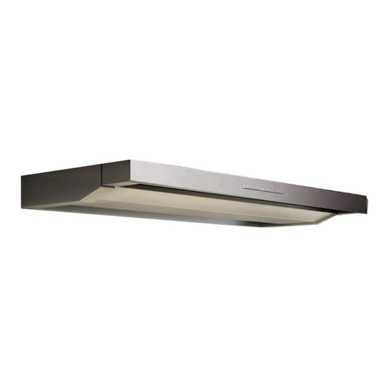
Berbel BEH 90 FL Installation Instructions Manual
Built-in hoods
Hide thumbs
Also See for BEH 90 FL:
- Operating instructions manual (32 pages) ,
- Operating and installation instructions for the models (32 pages)

Related Manuals for Berbel BEH 90 FL


Summary of Contents for Berbel BEH 90 FL
-
Page 1: Installation Instructions
Built-in Hoods BEH 60/90 FL Installation Instructions 09/2009 English version of original German instructions... - Page 2 The illustrations contain portrayals in various grey the following text, our berbel built-in hoods BEH scales. Movements which are to be carried out are 60 FL and BEH 90 FL product is briefly referred to made clear using movement or direction arrows. If as device.
-
Page 3: Table Of Contents
Table of contents Safety ................................5 Proper use ................................5 Ban on independent conversions and modifications ..................5 Basic safety instructions .............................5 Structural features of the information on dangers ....................7 Structural features of notices regarding material or environmental damage............7 Description...............................8 Possible operating modes ..........................8 Basic information on the device..........................9 View of the device from above .........................10 View of the device from below with flap closed ....................11... - Page 4 Dismantling the device...........................36 Disposal.................................37 Disposing of packaging.............................37 deviceDisposal..............................37 Technical data ...............................38 Model plate ...............................38 Built-in hood BEH 60 FL ...........................38 Built-in hood BEH 90 FL ...........................38 Contacting the manufacturer..........................39...
-
Page 5: Safety
• Check the device and all parts for visible damage. In the event of damage, contact your specialist Proper use dealer or the berbel customer service. The device must only be used in flawless condition. The device can be used to extract cooking vapours during cooking. - Page 6 Safety Avoiding dangers due to electric shock designate a person to prevent the fuse from being switched on. • Have work on the voltage supply carried out by a qualified, trained specialist electrician only. − Allow the device to dry. At the very least, the specialist electrician must −...
-
Page 7: Structural Features Of The Information On Dangers
Safety The device may only be installed above a fireplace Avoiding environmental damage for solid fuels (e.g. coal-fired stove) if: • Dispose of the device and its accessories • the fireplace has a sealed cover which cannot be according to the legal regulations. removed. -
Page 8: Description
Description Description The device intakes room air, filters the room air and returns the odour-free, cleaned room air into the The following illustrations show functions or room. dimensions. The devices which are used are shown as symbols. The illustrations are During installation, a recirculating air filter BUF is intended to provide assistance to the placed onto the device's fan outlet. -
Page 9: Basic Information On The Device
Description Basic information on the device Installation for hybrid mode The device is designed for installation in cupboards. The front panel can be pulled out to obtain a larger intake area. The rear end position of the front panel can be adjusted. The device's functions are controlled using the control in the centre of the front panel. -
Page 10: View Of The Device From Above
View of the device from above Built-in hood BEH 60 FL Contacts for window switches (multi-function contact) and wall box BMK Built-in hood BEH 90 FL Right bracket Fan outlet with guide aid for filter and outgoing Left bracket ... -
Page 11: View Of The Device From Below With Flap Closed
Description View of the device from below with flap closed Built-in hood BEH 60 FL Lighting ON/OFF button Built-in hood BEH 90 FL Lighting Extension Change output level button Flap with lower grease tray Switch on run-on button ... -
Page 12: View Of The Device From Below With Flap Open
Description View of the device from below with flap open Built-in hood BEH 60 FL "Capillar Trap" Built-in hood BEH 90 FL Flap with lower grease tray Upper grease tray ... -
Page 13: Air Extraction Mode
Installation must be carried out under adherence • Open the doors. to the official and legal regulations (e.g. state • Install a berbel wall box BMK. building ordinances). • Make sure that the open fireplace's prescribed In air extraction mode, the device intakes room air forced ventilation functions. -
Page 14: Outgoing Air In The Separate Outgoing Air Duct
Air extraction mode The device's optimal output is obtained if, when DANGER installing the outgoing air line, you ensure that: Fire hazard due to combustible • the outgoing air line is as short and direct as outgoing air line. possible If combustible outgoing air lines are •... - Page 15 60/90 N) and 150 mm in the case of 150 mm in accordance with systems (all other berbel extractor hoods). DIN 4102 Class A1. Each reduction of the outgoing air line generates If you use a chimney as an outgoing air line,...
- Page 16 Air extraction mode Make sure that the connection in the chimney is If the outgoing air line is routed through the roof, carried out using a bend which is bent upwards at you must ensure that: an angle of 90°. •...
- Page 17 Air extraction mode Make sure that • the slats of the louvered cover of the wall box are not narrow and thick • the slats of the louvered cover of the wall box are not positioned sharply downwards. • no insect screen is installed in the wall box. Insect screens impair the cross-section of the outgoing air line completely.
-
Page 18: Preparing For Installation
(e.g. 16 mm wooden plate). In the case of other installation conditions, contact berbel Required aids Ablufttechnik GmbH and ask about The following tools, materials and underlays are alternative mounting options prior to required for installation: installation. -
Page 19: Unpacking
If available, cut through the retaining strap with a Check the supplied parts for damage. pair of scissors. If parts are damaged or missing, contact your Cut through the packing tape with a pair of specialist berbel dealer or the customer service. scissors. - Page 20 Preparing for installation Scope of delivery, BEH 60 FL Scope of delivery, BEH 90 FL 6 × 8 × Built-in hood BEH 60 FL Built-in hood BEH 90 FL Left bracket Left bracket Right bracket Right bracket ...
-
Page 21: Removing Parts For Installation
Preparing for installation Removing the lower tray (lower grease Optional accessories tray) Optional accessories: Open the flap by pulling it downwards at the rounded edge. Grip the grease tray, which is folded down vertically, at the sides using both hands. Raise the lower grease tray approx. -
Page 22: Removing The "Capillar Trap
Preparing for installation Removing the brackets Remove the lower grease tray. Proceed as follows to remove the brackets from the device: Press both levers at the side in the "Capillar Trap" shaft backwards (1.) until they audibly engage. Pull the two brackets off (2.). Mark the brackets "Left"... - Page 23 Preparing for installation A saw (e.g. jigsaw) is required for this step. Protect all surfaces within your working area from damage, e.g. with thick cardboard or foamed material. Saw out the installation cut-out according to the dimensions specified for your device.
-
Page 24: Installing The Device
Recommended distance: stable cupboard (e.g. 16 mm 550 mm wooden plate). In the case of other installation conditions, contact berbel Ablufttechnik GmbH and ask about alternative mounting options prior to installation. Make sure that the device is mounted correctly. -
Page 25: Installing The Brackets
Installing the device Installing the brackets Repeat the procedure with the left bracket. A large Phillips screwdriver is required for this step. Attaching the device The two brackets which are contained in the scope of delivery are screwed laterally to the inner walls of DANGER the cupboard. -
Page 26: Aligning The Device Horizontally
Installing the device Adjusting the stop for the depth setting The levers automatically engage in the end position and hold the device. A 2.5 mm Allen ball key is required for this step. Push the device upwards until both levers The position of the front panel can be adjusted engage. -
Page 27: Connecting The Connection Contact For Wall Box And Window Switch (Multi-Function Contact)
Installing the device Push the front panel to the desired position. A window switch and a berbel wall box (e.g. BMK-F) can be connected to the device. The cable Make sure that the front panel is in the correct terminals for this are mounted on the device's fan position. - Page 28 Make sure that the control cable's insulation is not For this step, a small standard screwdriver is in the terminal. required for the connection terminals in the berbel extractor hood. Route the wall box control cable to the extractor hood.
- Page 29 Installing the device Tighten the screw for terminal 1. For this step, a small standard screwdriver is required for the connection terminals in the berbel extractor hood. Route the window switch control cable to the extractor hood. Make sure that the terminals for the multi-function connection in the extractor hood are accessible.
-
Page 30: Creating The Outgoing Air Connection
Installing the device Creating the outgoing air connection Take up offset wire 1 of the control cable. Guide wire 1 into terminal 1. The device can be installed for various operating modes: Make sure that the control cable's wire connector sleeve is completely in the terminal. - Page 31 Installing the device Position the recirculating air filter on the device ATTENTION from above using the folding handle. Damage due to falling parts. Protect surfaces and devices (e.g. cooled cooker top) beneath your working area from damage, e.g. with thick cardboard. Push the outgoing air line firmly onto the fan's guide aid.
-
Page 32: Installing The Removed Parts
Installing the device CAUTION Risk of injury due to falling parts. Make sure that nobody is standing beneath the device during work. ATTENTION Damage due to falling parts. Protect surfaces and devices (e.g. cooled cooker top) beneath your working area from damage, e.g. -
Page 33: Connecting The Current Supply
Installing the device Installing the "Capillar Trap" Press the grease tray backwards into the device (1.). Insert the "Capillar Trap" into the device by pressing it firmly upwards. Pull the grease tray downwards (2.) until it engages. The "Capillar Trap" does not engage; instead, it is merely clamped in. - Page 34 Installing the device Insert the mains plug into the socket. The berbel extractor hood is installed and ready to operate.
-
Page 35: Cleaning Surfaces
Cleaning surfaces Cleaning surfaces ATTENTION Damage to surfaces due to sharp- edged objects or aggressive cleaning agents. Never use sharp-edged objects, scouring agents or aggressive cleaning agents. Use a soft, moist cloth. Clean surfaces with a soft, moist cloth and a mild household cleaning agent. -
Page 36: Dismantling The Device
Dismantling the device Dismantling the device Pull the mains plug off. Remove any existing connection cables for the DANGER wall box and multi-function contact. Hybrid and air extraction mode only: Fatal electric shock due to improperly Remove the outgoing air line. carried out electrical work. -
Page 37: Disposal
Disposal Disposal Dispose of the packaging according to material segregation and in an environmentally-friendly manner. Disposing of packaging DANGER deviceDisposal Danger of suffocation due to parts of the packaging (e.g. films and polystyrene). Store film or other parts of the packaging in a location which is inaccessible to children. -
Page 38: Technical Data
Technical data Technical data Built-in hood BEH 90 FL Width 899 mm Model plate Depth 330 mm The model plate can be found inside the device Height 363 mm behind the lower grease tray flap. Max. fan output, 1 fan with 600 m³/h... -
Page 39: Contacting The Manufacturer
Contacting the manufacturer Contacting the manufacturer If you have any questions which are not answered by these instructions, contact: berbel Ablufttechnik GmbH Sandkampstraße 100 D-48432 Rheine Telephone +49 (0)800/56 06 06-0* +49 (0)800/56 06 06-1* Internet www.berbel.de *) Free from the German land line... - Page 40 © KONTECXT GmbH Technische Dokumentation D-45145 Essen www.technische-dokumentation.de Printed in Germany...
Need help?
Do you have a question about the BEH 90 FL and is the answer not in the manual?
Questions and answers