
Related Manuals for Berbel BLB 60 FL


Summary of Contents for Berbel BLB 60 FL
- Page 1 Fan Module BLB Operating and installation instructions for the models: BLB 60 FL / BLB 90 FL BLB 60 FLE / BLB 90 FLE 01/2011 (updated 08/2015) English translation of the German original manual...
- Page 2 The illustrations consist of greyscale representations. In the following text, our product the berbel- Lüfterbaustein BLB 60 FL, BLB 90 FL, BLB 60 FLE If elements are referred to in the text or in the legends, and BLB 90 FLE will be referred to as the 'device' in these elements are marked with a position number ...
-
Page 3: Table Of Contents
Most functions (operation, maintenance) and the assembly of all devices which are described in these instructions are identical. All the following descriptions and illustrations are therefore valid for the berbel- fan fodule BLB 60 FL, BLB 60 FLE, BLB 90 FL and BLB 90 FLE. - Page 4 Remove the bracket..............................44 Create the installation cut-out ...........................44 Installing the device ..............................45 Safety distances are observed ..........................46 Fitting the bracket BLB 60 FL(E) ..........................46 Fitting the bracket BLB 90 FL(E) ..........................47 Hang the device ................................48 Align the device horizontally .............................49 Secure the lock .................................49...
-
Page 5: Safety
§ Do not undertake and independent modifications of moderate injuries. or conversions to the device. Conversions or modifications without the approval of berbel Layout of notices regarding damage to Ablufttechnik GmbH are not permitted. property or the environment §... -
Page 6: General Safety Instructions
If fluid does enter the device: damage. In the event of damage, contact your - Immediately shut off the power supply dealer or berbel customer service. You may only by removing the fuse, for example. use the device if it is in perfect working order. -
Page 7: Safety Instructions For The Installer
Safety instructions for the installer Avoiding the risk of explosion Operating over a solid-fuel burning fireplace: The device may only be used over a fireplace for solid § Do not operate the device in an environment with a fuels (e.g. a coal-burning stove) if: risk of explosion. - Page 8 In the event of damage, contact your an all-pole isolating device with a contact gap of at dealer or berbel customer service. You may only least 3 mm must be installed and accessible. install the device if it is in perfect working order.
- Page 9 Safety instructions for the installer Minimising the danger of collapse The device may only be installed over a fireplace for solid fuels (e.g. a coal-burning stove) if: In extracted air mode: § the fireplace has a sealed cover which cannot be §...
-
Page 10: Operating Instructions
Operating instructions Operating instructions Recirculated air mode The filter filling must be replaced at regular Description for the user intervals in recirculated air mode. The following illustrations show the way the possible operating modes work. The devices used are shown as symbols. The illustrations are meant to serve as a guide. -
Page 11: Device View With Closed Lower Section
All the following descriptions and illustrations are therefore valid for the berbel- fan module BLB 60 FL, BLB 60 FLE, BLB 90 FL and BLB 90 FLE. The berbel- fan module BLB 90 FL is mainly shown in the illustrations. -
Page 12: Device View With Opened Lower Section
All the following descriptions and illustrations are therefore valid for the berbel- fan module BLB 60 FL, BLB 60 FLE, BLB 90 FL and BLB 90 FLE. The berbel- fan module BLB 90 FL is mainly shown in the illustrations. -
Page 13: Operating
Operating Turning on the ventilation function Operating WARNING WARNING Explosion risk and fire hazard from gas Suffocation risk due to low oxygen or explosive or flammable gas mixtures levels when operating the device. in the kitchen when operating electrical Ø Ensure there is an adequate supply equipment. -
Page 14: Changing The Power Level
Operating You can operate the device in four different power ATTENTION levels. Risk of fire due to flambéing or To turn the device on, proceed as follows: overheated oil and fat under the Ø Turn the rotary knob clockwise from level "0" to the device. -
Page 15: Turning Off The Ventilation Function
Operating Turning off the ventilation function To turn off the ventilation function, proceed as follows: Ø Turn the rotary knob anti-clockwise to the "0" position. The rotary knob snaps into each power level. The device turns off the ventilation function. Operating instructions... -
Page 16: Turning The Lighting On And Off
Operating Turning the lighting on and off Turn the lighting off The device is fitted with an energy saving LED light to To turn off the lighting, proceed as follows: light up the hob. Ø Press on the rotary knob with a finger. The lighting can be used independently from the fan. -
Page 17: Cleaning
Cleaning Proceed as follows to clean the device at normal Cleaning soiling levels: Ø Turn off the device. DANGER Ø Open the lower section by pulling the rounded Fatal electrical shocks through liquids edge on the front side downwards. that get into the device. Ø... -
Page 18: Cleaning When Heavily Soiled
Cleaning Cleaning when heavily soiled Ø Use a soft, damp cloth or kitchen paper towels for cleaning. If the device is heavily soiled, you must remove the lower section and the capillary trap. These can be Ø Wipe off the upper and lower sections. easily removed and refitted, and they can be reused Ø... - Page 19 Cleaning Remove the capillary trap Clean the parts Ø Grasp the sides of the capillary trap with both ATTENTION hands. Ø Pull the capillary trap downwards. Damage to the lower section by improper cleaning. Ø Clean the lower section e.g. with a damp cloth.
-
Page 20: Cleaning The Surfaces
Cleaning Reassemble the lower section. Close the lower section. Ø Grip the lower section with both hands. Ø Close the lower section by pushing it upwards until the two magnetic fasteners can be heard to click Ø Insert the lower section into the device from below together. -
Page 21: Cleaning The Rotary Knob
Cleaning Cleaning the rotary knob Fitting the rotary knob The rotary knob (ThinCoder) is fitted to the device on ATTENTION one axis. This axis has been milled off on one side. A matching opening is found as a counterpart on the Damage to the rotary knob through underside of the rotary knob. -
Page 22: Maintenance
The device is fitted with LED lighting. The bulbs have a service life of approximately 50,000 operating hours. ATTENTION Ø If you have any problems, contact your berbel Damage caused by falling parts. dealer or customer services. Ø Protect areas and devices (e.g. - Page 23 Maintenance Removing the hybrid filter Remove the recirculation air filters. To change the filter filling, proceed as follows: To change the filter filling, proceed as follows: Ø Remove the exhaust pipe from the socket. Ø Lift the filter at least 3 cm (1.). Ø...
- Page 24 Maintenance Replace the filter Only in hybrid operation: To make sure that the filter is installed correctly, Ø Push the exhaust pipe onto the filter collar. a guide is installed on the filter seating. Ø Insert the filter into the device from the top. Ø...
-
Page 25: Troubleshooting
Open the window. window contact switch and the window is closed. BLB 60 FLE/90 FLE: No power supply or connecting cable is Please consult your berbel dealer. External fan does not not plugged in or connected. function. The lighting does not The bulb has blown. - Page 26 22. The exhaust pipe was not properly Please consult your berbel dealer or berbel connected or installed. customer services. Ø If the fault persists, please contact your berbel dealer or berbel customer services. Operating instructions...
-
Page 27: Installation Instructions
Installation instructions Installation instructions Ø Make sure that the cross-section of the ventilation slits in the top structure is more than 300 cm². Description for the installer Ø Make sure that the air can flow freely out of the device. Possible operating modes Ø... -
Page 28: Information About Extracted Air Mode
§ Open the window. § Open the door. The filter's filling needs to be regularly replaced. § Install a berbel BMK wall box. § Ensure that the prescribed forced ventilation of the open fire is working. Installation instructions... - Page 29 Installation instructions § The exhaust hose is as short and direct as possible. WARNING § The room air to be extracted is able to flow freely through the exhaust pipe without turbulence and Suffocation risk due to low oxygen back pressure. levels when operating the device.
- Page 30 The minimum cross-section for the exhaust pipe for the expect increased air resistance in relation to the length 125-systems (BEH 60/90 and BLB 60 FL/90FL) is 125 of the chimney. mm and for the 150 systems (all other berbel extractor hoods) is 150 mm.
- Page 31 Installation instructions The extracted air must be introduced into the chimney If you run the exhaust pipe out through the roof, you using a 90° bend pointing upwards. This will prevent a must ensure that: possible back pressure. § The pipe diameter of the fan outlet is not larger than the diameter of the roof feed through.
- Page 32 Installation instructions Ensure that: § The slats of the wall box's louvred cover are not narrow and thick. § The slats of the wall box's louvred cover do not hang straight down. § There is no insect screen fitted in the wall box. Insect screens impair the cross-section of the exhaust pipe completely.
-
Page 33: Basics About The Device
Description for the installer Basics about the device The device is designed to be installed flush in cupboards. The BLB 60 FLE and BLB 90 FLE devices are operated with an external fan. The device is controlled using the controls in the To ensure the device functions optimally, it is middle of the front panel. -
Page 34: Device View From Above
Description for the installer Device view from above Fan module BLB 60 FL Right bracket Fan module BLB 90 FL Left bracket As a option, only for BLB 60 FLE and BLB 90 FLE: Only BLB 60 FLE and BLB 90 FLE: ... -
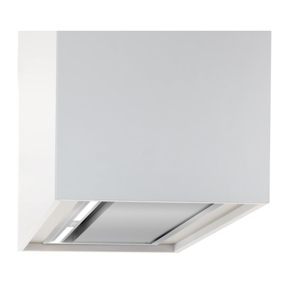
Page 35: Device View From Underneath With A Closed Lower Section
Description for the installer Device view from underneath with a closed lower section Fan module BLB 90 FL Lower section Fan module BLB 60 FLE Illumination Rotary knob (on and off switch) Installation instructions... -
Page 36: Device View From Underneath With Opened Lower Section
Description for the installer Device view from underneath with opened lower section Fan module BLB 90 FL Capillary trap Fan module BLB 60 FLE Lower section Upper section Installation instructions... -
Page 37: Preparation For Installation
Preparation for installation Qualifications of personnel Preparation for installation Two persons are required to mechanically install the In this chapter you will learn what the prerequisites are device. for installation. Perform all the steps in this guide one after the other. These technicians must have sufficient craftsman skills and knowledge. -
Page 38: Brief Overview Of The Installation
Preparation for installation Brief overview of the installation Prepare the plug socket for the power supply The installation is done in the following steps: DANGER § Remove the lower section. Lethal electric shock caused by § Remove the capillary trap. improper connection. - Page 39 You can connect the device to a window contact switch Wall box BMK F and a berbel wall box (e.g. BMK F). The cable clamps are fitted to the device's housing. The connection Control contact, potential-free cables should be laid prior to installing the device.
-
Page 40: Tools And Equipment Needed
Preparation for installation Tools and equipment needed Unpacking For installation you need the following tools, materials CAUTION and documents: Risk of injury from broken glass. Ø Wear protective gloves. Ø Unpack the device carefully. Ø Do not touch broken glass. ATTENTION Damage to the surfaces from improper unpacking. -
Page 41: Check The Delivery
Ø Check the delivered parts for damage. Ø If any parts are damaged or missing, contact your berbel dealer or customer services. Scope of delivery BLB 60 FL(E) Ø Take the loose parts out of the packaging. CAUTION Risk of injury from the heavy extractor hood falling. -
Page 42: Remove The Parts For Installation
Preparation for installation Scope of delivery BLB 90 FL(E) Optional accessories Fan module BLB 90 FL(E) Only for hybrid mode: Left bracket Hybrid filter BHF 125 Right bracket Only for recirculated air mode: Installation Instructions ... -
Page 43: Remove The Lower Section
Preparation for installation Remove the lower section Ø Remove the lower section. Ø Open the lower section by pulling the lower section downwards on the rounded edge. Ø Grasp the lower section on its sides with both hands Remove the capillary trap when it is hanging down perpendicularly. -
Page 44: Remove The Bracket
The installation cut-out must have the following follows: dimensions: Ø Press both levels at the side in the bay for the BLB 60 FL BLB 90 FL capillary trap backwards (1.) until they are heard to BLB 60 FLE BLB 90 FLE click into place. -
Page 45: Installing The Device
Installing the device Installing the device Ø Cut out the installation cut-out in accordance with the dimensions specified for your device. WARNING Risk of injury from falling parts. Ø Ensure that no-one is below the working area during the work. WARNING Risk of injury from falling parts if improperly fastened. -
Page 46: Safety Distances Are Observed
Installing the device Safety distances are observed Fitting the bracket BLB 60 FL(E) The following illustrations show the operation or The supplied brackets are suitable for 16 mm to dimensions. 22 mm thick cabinet bases. The corresponding The devices used are shown as symbols. The dimension must be adjusted by the installer. -
Page 47: Fitting The Bracket Blb 90 Fl(E)
Installing the device Fitting the bracket BLB 90 FL(E) Ø Ensure that the bracket is firmly mounted in the correct installation position. The supplied brackets are suitable for 16 mm to 22 mm thick cabinet bases. The corresponding dimension must be adjusted by the installer. For this work step you need a large Phillips screwdriver. -
Page 48: Hang The Device
Installing the device Hang the device Ø Ensure that the bracket is firmly mounted in the correct installation position. DANGER Danger from falling parts if improperly fastened. Ø The supplied fastening material is only to be used for installation into an installation cut-out in a bearing and stable wooden cabinet (e.g. -
Page 49: Align The Device Horizontally
Installing the device Align the device horizontally For this step you do not require any tools. You can slightly adjust the horizontal alignment of the device. Proceed as follows: Ø Push the device into the desired position by pushing against the device on the side with your hand. Secure the lock For this work step you need a 2.5 mm ball Allen key. -
Page 50: Only Blb 60 Fle / Blb 90 Fle: Connect The Connection Cable Of The Fan
fan to the receptacle on the device. For this work step, you do not need any tools to connect the berbel connection cable. Proceed as follows: Ø Push the plug of the connection cable firmly into the receptacle on the device. -
Page 51: Connecting The Wall Box And The Window Contact Switch Contacts
You can connect the device to a window switch and a Control cable berbel wall box (e.g. BMK F). The cable clamps for this Power supply are attached to the fan housing of the device. Wall box BMK F ... - Page 52 Ø Make sure that the insulation of the control cable is not in the terminal. For this work step, you need a small Phillips screwdriver for the connection terminals in the berbel extractor hood. Ø Lay the control cable from the wall box to the extractor hood.
- Page 53 For this work step, you need a small Phillips Ø Make sure that the insulation of the control cable is screwdriver for the connection terminals in the berbel not in the terminal. extractor hood. Ø Lay the window switch's control cable to the device.
-
Page 54: Creating The Exhaust Air Connection
Installing the device Ø Tighten the screw of terminal 1. CAUTION Risk of injury from falling parts. Ø Ensure that no-one is underneath the device while working. ATTENTION Damage caused by falling parts. Ø Protect areas and devices (e.g. cooled cooking hob) underneath the working area against damage, e.g. - Page 55 Installing the device Installing the device for extracted air mode Ø Ensure that the exhaust pipe is correctly fitted. WARNING Risk of falling during work carried out at height. Ø Use a stable step-ladder. CAUTION Risk of injury from falling parts. Ø...
- Page 56 Installing the device Installing the device for hybrid mode Ø Place the hybrid filter onto the guide on the fan housing from above. WARNING Risk of falling when changing the filter or during work carried out at height. Ø Use a stable step-ladder. CAUTION Risk of injury from falling parts.
-
Page 57: Install The Other Parts
Installing the device Install the other parts Ø Press the lower section rearwards into the device (1.). After installation, fit the parts removed as follows: Ø Pull the lower section downwards (2.) until it clicks into place. Insert the capillary trap Ø... -
Page 58: Connect The Power Supply
Ø Dry the surfaces using a soft cloth. Cleaning the controls Ø Clean the surface of the control panel with a soft, damp cloth. Ø Dry the surfaces using a soft cloth. The berbel extractor hood is installed and ready for use. Installation instructions... -
Page 59: Disassembling The Device
Disassembling the device Disassembling the device To remove the device, proceed as follows: Ø Disconnect the power supply to the device on all DANGER poles. Ø Remove the mains plug. Lethal electric shock caused by improperly performed electrical work. Ø Remove the connection cables for the wall box and the multi-function contact, if fitted. -
Page 60: Disposal
Disposal Disposal Ø Dispose of the packaging, separated into material groups, in an environmentally friendly way. Disposal of the packaging Disposal DANGER Danger of suffocation from packaging components (e.g. foils and polystyrene). Ø Store the film or other parts of the packaging in a location which is inaccessible to children. -
Page 61: Technical Specifications
400 m³/h § Symbols of compliance with the legal requirements and test symbols. Power level 4: min. 500 m³/h Fan module BLB 60 BLB 60 FL BLB 60 FLE BLB 90 FL BLB 90 FLE Width 550 mm 550 mm... -
Page 62: Contact
Contact If you have suggestions or queries, please choose from the following possibilities: Post: berbel Ablufttechnik GmbH Sandkampstraße 100 D-48432 Rheine Telephone: +49 (0)5971 / 80 80 9-0 Mon to Thu 08.00 to 17.00 and Fri 08.00 to 14.00 Fax:... - Page 63 Contact...
- Page 64 German language original manual created by: B. Gebhardt - Büro für Technische Dokumentation 45891 Gelsenkirchen www.tddv.de Printed in Germany Version: 04.08.2015 16:21 6001431 Subject to alterations without notice...
Need help?
Do you have a question about the BLB 60 FL and is the answer not in the manual?
Questions and answers