Dell PowerEdge R930 Owner's Manual
Hide thumbs
Also See for PowerEdge R930:
- Getting started (2 pages) ,
- Owner's manual (199 pages) ,
- Getting started with your system (6 pages)

Related Manuals for Dell PowerEdge R930


Summary of Contents for Dell PowerEdge R930
- Page 1 Dell PowerEdge R930 System Owner's Manual Regulatory Model: E37S Series Regulatory Type: E37S001...
- Page 2 WARNING: A WARNING indicates a potential for property damage, personal injury, or death. Copyright © 2015 Dell Inc. All rights reserved. This product is protected by U.S. and international copyright and intellectual property laws. Dell and the Dell logo are trademarks of Dell Inc.
-
Page 3: Table Of Contents
Contents 1 About the PowerEdge R930................9 ......................9 Front panel features and indicators ..........................11 LCD panel features ..........................12 Home screen ............................12 Setup menu ............................. 13 View menu ...........................13 Diagnostic indicators ........................15 Hard drive indicator codes ........................16 SSD LED indicator pattern ..................... - Page 4 About Boot Manager ........................ 39 Entering Boot Manager ......................39 Boot Manager main menu ......................40 About Dell Lifecycle Controller ........................40 Changing the boot order ...................... 40 Choosing the system boot mode ....................41 Assigning a system or setup password .................41...
- Page 5 .........................60 Memory mirroring ........................61 Fault Resilient Memory ....................61 Sample memory configurations ............................62 Memory riser ....................62 Removing a memory riser blank .....................63 Installing a memory riser blank ......................64 Removing a memory riser .......................65 Installing a memory riser ..............66 Removing memory modules from the memory riser ..............
- Page 6 ............................. 97 NDC riser ....................... 98 Removing the NDC riser ......................... 99 Installing the NDC riser ........................99 Network daughter card ..................100 Removing the network daughter card ..................101 Installing the network daughter card ........................101 SD vFlash media card ....................102 Replacing an SD vFlash media card ........................
- Page 7 ............... 162 When to use the embedded system diagnostics ..........162 Running the Embedded System Diagnostics from Boot Manager .....163 Running the Embedded System Diagnostics from the Dell Lifecycle Controller ......................163 System diagnostic controls 7 Jumpers and connectors................164 ......................164...
- Page 8 .........................165 System board connectors ......................168 Disabling a forgotten password 8 Technical specifications..................169 9 Getting help....................... 176 ..........................176 Contacting Dell ....................176 Locating your system Service Tag ......................176 Quick Resource Locator (QRL)
-
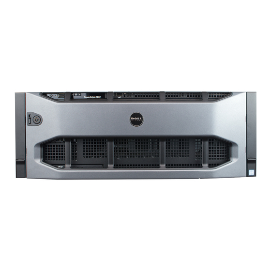
Page 9: About The Poweredge R930
About the PowerEdge R930 The Dell PowerEdge R930 is a rack server that supports up to four processors based on the Intel E7-8800/4800 v3 product family, eight memory risers with a capacity of 12 DIMMs per riser, and up to 24 hard drives/SSDs. - Page 10 Item Indicator, Button, or Icon Description Connector vFlash media card slot Enables you to insert a vFlash media card. Power-on indicator, The power-on indicator lights when the system power button power is on. The power button controls the power supply output to the system. NOTE: On ACPI-compliant operating systems, turning off the system using the power button causes the system to perform a graceful...
-
Page 11: Lcd Panel Features
Item Indicator, Button, or Icon Description Connector 24 depending on the NOTE: On the backplane supported Flash backplane devices, there are 3 bays in total. The first two configurations) bays are for PCIe Flash devices with two sets of drives labelled 0 through 3. The bay 3 is for SAS drives labelled 0 through 15. -
Page 12: Home Screen
SEL. This is useful when trying to match an LCD message with an SEL entry. Select Simple to display LCD error messages in a simplified user-friendly description. For more information on error messages, see the Dell Event and Error Messages Reference Guide at dell.com/esmmanuals. Set home Select the default information to be displayed on the LCD Home screen. -
Page 13: View Menu
For more standby, and if any error information on error messages, see the Dell exists (for example, a failed Event and Error Messages Reference Guide fan or hard drive). - Page 14 Icon Description Condition Corrective action Electrical The indicator blinks amber if See the System Event Log or system indicator the system experiences an messages for the specific issue. If it is due to electrical error (for example, a problem with the power supply, check the voltage out of range, or a LED on the power supply.
-
Page 15: Hard Drive Indicator Codes
Hard drive indicator codes Figure 3. Hard drive indicators hard drive activity indicator hard drive status indicator hard drive NOTE: If the hard drive is in Advanced Host Controller Interface (AHCI) mode, the status indicator (on the right side) does not function and remains off. Drive-status indicator pattern (RAID only) Condition Blinks green two times per second... -
Page 16: Ssd Led Indicator Pattern
SSD LED indicator pattern Figure 4. SSD LED indicator pattern SSD activity indicator SSD status indicator While the operating system is running, the status indicator provides the current status of the device. The following table lists the device states along with the associated LED indicator codes. Table 1. -
Page 17: Back Panel Features And Indicators
State Name Slot/Device State Status LED (Green) Status LED (Amber) encountered a critical error condition. Back panel features and indicators Figure 5. Back panel features and indicators Item Indicator, Button, or Icon Description Connector Power supply unit (PSU 750 W or 1100 W 3 and 4) PCIe expansion card Enables you to connect PCI Express expansion... - Page 18 Item Indicator, Button, or Icon Description Connector Four integrated connectors that include: • Two 10/100/1000 Mbps NIC connectors • Two 100 Mbps/1 Gbps/10 Gbps SFP+/10 GbE T connectors USB connectors (2) Enables you to connect USB devices to the system. The ports are USB 2.0-compliant.
-
Page 19: Nic Indicator Codes
NIC indicator codes Figure 6. NIC indicators link indicator activity indicator Convention Indicator pattern Description Link and activity indicators The NIC is not connected to the network. are OFF Link indicator is green The NIC is connected to a valid network at its maximum port speed (1 Gbps). - Page 20 CAUTION: Do not disconnect the power cord or unplug the PSU when updating firmware. If firmware update is interrupted, the PSUs will not function. You must roll back the PSU firmware by using Life cycle controller. See Dell Lifecycle Controller User’s Guide at Dell.com/esmmanuals. Flashing green...
-
Page 21: Documentation Matrix
Dell.com/poweredgemanuals Install the operating system Operating system documentation at Dell.com/ operatingsystemmanuals Get an overview of the Dell Systems Management Dell OpenManage Systems Management Overview offerings Guide at Dell.com/openmanagemanuals Configure and log in to iDRAC, set up managed... -
Page 22: Quick Resource Locator (Qrl)
Use the Quick Resource Locator (QRL) to get immediate access to system information and how-to videos. This can be done by visiting Dell.com/QRL or by using your smartphone or tablet and a model specific Quick Resource (QR) code located on your Dell PowerEdge system. To try out the QR code, scan... -
Page 23: Performing Initial System Configuration
Turn on the system by pressing the power button or using iDRAC. Turn on the attached peripherals. Setting up and configuring the iDRAC IP address You can set up the Integrated Dell Remote Access Controller (iDRAC) IP address by using one of the following interfaces: •... -
Page 24: Logging In To Idrac
For more information on setting up and configuring iDRAC, see the Integrated Dell Remote Access Controller User's Guide at Dell.com/esmmanuals. Logging in to iDRAC You can log in to iDRAC as an iDRAC local user, a Microsoft Active Directory user, or a Lightweight Directory Access Protocol (LDAP) user. -
Page 25: Downloading Drivers And Firmware
NOTE: If you do not have the Service Tag, select Automatically detect my Service Tag for me to allow the system to automatically detect your Service Tag, or select Choose from a list of all Dell products to select your product from the Product Selection page. Click Get drivers and downloads. -
Page 26: Pre-Operating System Management Applications
Your system has the following pre-operating system management applications: • System Setup • Boot Manager • Dell Lifecycle Controller Navigation keys The navigation keys can help you quickly access the pre-operating system management applications. Description <Page Up> Moves to the previous screen. -
Page 27: About System Setup
The iDRAC Settings utility is an interface to set up and configure the iDRAC parameters by using UEFI. You can enable or disable various iDRAC parameters by using the iDRAC Settings utility. For more information about this utility, see the Integrated Dell Remote Access Controller User’s Guide at Dell.com/esmmanuals. Device Settings Enables you to configure device settings. -
Page 28: System Information Screen
Menu Item Description System Information Displays information about the system such as the system model name, BIOS version, and Service Tag. Memory Settings Displays information and options related to the installed memory. Processor Settings Displays information and options related to the processor such as speed, cache size. -
Page 29: Memory Settings Screen
Memory Settings screen You can use the Memory Settings screen to view all the memory settings as well as enable or disable specific memory functions such as system memory testing and node interleaving. To view the Memory Setting screen, click System Setup Main Menu → System BIOS → Memory Settings. Menu Item Description System Memory Size... -
Page 30: Processor Settings Screen
Processor Settings screen You can use the Processor Settings screen to view the processor settings and perform specific functions such as enabling virtualization technology, hardware prefetcher, and logical processor idling. To view the Processor Settings screen, click System Setup Main Menu → System BIOS → Processor Settings. -
Page 31: Sata Settings Screen
Menu Item Description NOTE: The processor bus speed option displays only when both processors are installed. Processor 1 NOTE: Depending on the number of installed CPUs, there may be up to four processor listings. The following settings are displayed for each processor installed in the system. -
Page 32: Boot Settings Screen
Menu Item Description Port C Sets the drive type of the selected device. For Embedded SATA settings in ATA mode, set this field to Auto to enable BIOS support. Set it to OFF to turn off BIOS support. For AHCI mode or RAID mode, BIOS always enables support. Model Displays the drive model of the selected device. -
Page 33: Network Settings Screen
Network Settings screen You can use the Network Settings screen to modify PXE device settings. The Network Settings option is available only in the UEFI boot mode. BIOS does not control network settings in the BIOS boot mode. For BIOS boot mode, the network settings are handled by the network controllers option ROM. To view the Network Settings screen, click System Setup Main Menu →... -
Page 34: Serial Communication Screen
Controller is the only display capability in the system (that is, no add-in graphics card is installed), then the Embedded Video Controller is automatically used as the primary display even if the Embedded Video Controller setting is Disabled. Current State of Embedded Video Controller Displays the current state of the Embedded Video Controller. -
Page 35: System Profile Settings Screen
You can only change the rest of the options if the mode is set to Custom. By default, the System Profile option is set to Performance Per Watt Optimized (DAPC). DAPC is Dell Active Power Controller. NOTE: The following parameters are available only when the System Profile option is set to Custom. - Page 36 Menu Item Description Turbo Boost Enables or disables the processor to operate in turbo boost mode. By default, the Turbo Boost option is set to Enabled. Energy Efficient Turbo Enables or disables the Energy Efficient Turbo. Energy Efficient Turbo (EET) is a mode of operation where a processor’s core frequency is adjusted within the turbo range based on workload.
-
Page 37: System Security Settings Screen
System Security Settings screen You can use the System Security screen to perform specific functions such as setting the system password, setup password and disabling the power button. To view the System Security screen, click System Setup Main Menu → System BIOS → System Security Settings. -
Page 38: Miscellaneous Settings Screen
Menu Item Description User Defined Delay (60s to Sets the User Defined Delay when the User Defined option for AC Power 240s) Recovery Delay is selected. UEFI Variable Access Provides varying degrees of securing UEFI variables. When set to Standard (the default), UEFI variables are accessible in the Operating System per the UEFI specification. -
Page 39: About Boot Manager
Menu Item Description Keyboard NumLock Enables you to set whether the system boots with the NumLock enabled or disabled. By default the Keyboard NumLock is set to On. NOTE: This option does not apply to 84-key keyboards. F1/F2 Prompt on Error Enables or disables the F1/F2 prompt on error. -
Page 40: About Dell Lifecycle Controller
Diagnostics and UEFI shell. About Dell Lifecycle Controller Dell Lifecycle Controller allows you to perform tasks such as configuring BIOS and hardware settings, deploying an operating system, updating drivers, changing RAID settings, and saving hardware profiles. For more information about Dell Lifecycle Controller, see the documentation at Dell.com/esmmanuals. -
Page 41: Assigning A System Or Setup Password
Assigning a system or setup password Prerequisites NOTE: The password jumper enables or disables the System Password and Setup Password features. For more information on the password jumper settings, see System board jumper settings. You can assign a new System Password or Setup Password or change an existing System Password or Setup Password only when the password jumper setting is enabled and Password Status is set to Unlocked. -
Page 42: Deleting Or Changing An Existing System Password Or Setup Password
Steps Turn on or reboot your system. Type your system password and press Enter. Next steps When Password Status is Locked, type the password and press <Enter> when prompted at reboot. NOTE: If an incorrect system password is entered, the system displays a message and prompts you to re-enter your password. -
Page 43: Embedded System Management
NOTE: Accessing some of the features on the iDRAC Settings utility requires the iDRAC Enterprise License upgrade. For more information on using iDRAC, see the iDRAC User's Guide at dell.com/esmmanuals. Entering the iDRAC Settings utility Turn on or restart the managed system. - Page 44 Enter the iDRAC Settings utility. Under iDRAC Settings → Thermal → User Option, select one of the following options: • Default • Maximum Exhaust Temperature • Fan Speed Offset NOTE: When the User Option is set to the default Auto setting, the user option cannot be modified.
-
Page 45: Installing And Removing System Components
• Hard drive backplane • Processor blank and heat sink blank The following components are Field Replaceable Units (FRUs). Removal and installation procedures should be performed only by Dell certified service technicians. • Chassis intrusion switch • System board •... -
Page 46: Safety Instructions
Damage due to servicing that is not authorized by Dell is not covered by your warranty. Read and follow the safety instructions that came with the product. -
Page 47: Recommended Tools
Recommended tools You need the following items to perform the procedures in this section: • Key to the bezel lock • Phillips #2 screwdriver • Wrist strap Front bezel (optional) Installing the optional front bezel Locate and remove the bezel key. NOTE: The bezel key is attached to the bezel. -
Page 48: System Cover
Damage due to servicing that is not authorized by Dell is not covered by your warranty. Read and follow the safety instructions that came with the product. -
Page 49: Installing The System Cover
Steps Turn the latch release lock to the unlock position. Lift the latch and rotate the latch toward the back of the system. The system cover slides back disengaging the tabs on the system cover from the slots on the chassis. Hold the system cover on both sides, and lift the system cover away from the system. -
Page 50: Inside The System
Damage due to servicing that is not authorized by Dell is not covered by your warranty. Read and follow the safety instructions that came with the product. -
Page 51: Chassis Intrusion Switch
Damage due to servicing that is not authorized by Dell is not covered by your warranty. Read and follow the safety instructions that came with the product. -
Page 52: Installing The Chassis Intrusion Switch
Damage due to servicing that is not authorized by Dell is not covered by your warranty. Read and follow the safety instructions that came with the product. -
Page 53: Cable Management Tray
Damage due to servicing that is not authorized by Dell is not covered by your warranty. Read and follow the safety instructions that came with the product. - Page 54 Figure 12. Removing the cables routed through the cable management tray cable management tray release tab cables Figure 13. Removing and installing the cable management tray slots on the chassis (4) cable management tray hook (4)
-
Page 55: Installing The Cable Management Tray
Damage due to servicing that is not authorized by Dell is not covered by your warranty. Read and follow the safety instructions that came with the product. -
Page 56: System Memory
System memory Your system supports DDR4 ECC registered DIMMs (RDIMMs) and load reduced DIMMs (LRDIMMs) at DDR4 (1.2V) voltage specification. It also supports single, dual and quad rank DIMMs of up to 1866 MHz. NOTE: MT/s indicates DIMM speed in MegaTransfers per second. Memory bus operating frequency can be 1333 MT/s, 1600 MT/s, and 1866 MT/s depending on: •... - Page 57 Figure 14. Memory socket locations Memory channels are organized as follows: Processor 1 channel 0: slots A1, A5, and A9 channel 1: slots A2, A6, and A10 channel 2: slots A3, A7, and A11 channel 3: slots A4, A8, and A12 channel 0: slots B1, B5, and B9 channel 1: slots B2, B6, and B10 channel 2: slots B3, B7, and B11...
- Page 58 channel 1: slots E2, E6, and E10 channel 2: slots E3, E7, and E11 channel 3: slots E4, E8, and E12 channel 0: slots F1, F5, and F9 channel 1: slots F2, F6, and F10 channel 2: slots F3, F7, and F11 channel 3: slots F4, F8, and F12 Processor 4 channel 0: slots G1, G5, and G9...
-
Page 59: General Memory Module Installation Guidelines
DIMM Type DIMMs DIMM Size Operating Frequency Maximum DIMM Rank/ Populated/ (in MT/s) Channel Channel (DPC) DDR4 2133 MT/s (1.2 RDIMM 8 GB, 16 GB, 32 1866 Dual rank 8 GB, 16 GB, 32 1866 Dual rank 8 GB, 16 GB, 32 1333 Dual rank LRDIMM... -
Page 60: Advanced Ecc (Lockstep)
NOTE: You can mix x4 and x8 DRAM based DIMMs to support RAS features. However, all guidelines for specific RAS features must be followed. x4 DRAM based DIMMs retain Single Device Data Correction (SDDC) in memory optimized (independent channel) mode. x8 DRAM based DIMMs require Advanced ECC mode to gain SDDC. -
Page 61: Fault Resilient Memory
• Memory modules must be identical in size, speed, and technology. • Memory modules installed in memory module sockets with white release levers must be identical and the same rule applies for sockets with black and green release tabs. This ensures that identical memory modules are installed in matched pairs—for example, A1 with A3, A2 with A4, A5 with A7, and so on. -
Page 62: Memory Riser
Damage due to servicing that is not authorized by Dell is not covered by your warranty. Read and follow the safety instructions that came with the product. -
Page 63: Installing A Memory Riser Blank
Damage due to servicing that is not authorized by Dell is not covered by your warranty. Read and follow the safety instructions that came with the product. -
Page 64: Removing A Memory Riser
Damage due to servicing that is not authorized by Dell is not covered by your warranty. Read and follow the safety instructions that came with the product. -
Page 65: Installing A Memory Riser
Damage due to servicing that is not authorized by Dell is not covered by your warranty. Read and follow the safety instructions that came with the product. -
Page 66: Removing Memory Modules From The Memory Riser
Damage due to servicing that is not authorized by Dell is not covered by your warranty. Read and follow the safety instructions that came with the product. - Page 67 Figure 17. Opening and closing the memory riser memory riser flip out bracket (2) memory riser handle Locate the appropriate memory module socket. To release the memory module from the socket, simultaneously press the ejectors on both ends of the memory module socket. NOTE: Handle each memory module only by the card edges, making sure not to touch the middle of the memory module or metallic contacts.
-
Page 68: Installing Memory Modules Into The Memory Riser
Damage due to servicing that is not authorized by Dell is not covered by your warranty. Read and follow the safety instructions that came with the product. - Page 69 Steps To open the memory riser, open the flip out brackets on the memory riser. Locate the appropriate memory module socket. CAUTION: Handle each memory module only by the card edges, making sure not to touch the middle of the memory module or metallic contacts. If a memory module or a memory module blank is installed in the socket, remove it.
-
Page 70: Memory Riser And Fan Cage
Damage due to servicing that is not authorized by Dell is not covered by your warranty. Read and follow the safety instructions that came with the product. -
Page 71: Installing The Memory Riser And Fan Cage
Damage due to servicing that is not authorized by Dell is not covered by your warranty. Read and follow the safety instructions that came with the product. -
Page 72: Hard Drives
55 TB/year) will lead to significant risk and increase the drives failure rate. For more information on these hard drives, see the 512e and 4Kn Disk Formats whitepaper and 4K Sector HDD FAQ document at Dell.com/poweredgemanuals. Depending on the configuration, your system supports one of the following: Four hard drive Up to four 2.5 inch hot-swappable SAS hard drives, SATA hard drives, or SATA SSD... -
Page 73: Removing A 2.5 Inch Hard Drive Blank
Damage due to servicing that is not authorized by Dell is not covered by your warranty. Read and follow the safety instructions that came with the product. -
Page 74: Installing A 2.5 Inch Hard Drive Blank
Damage due to servicing that is not authorized by Dell is not covered by your warranty. Read and follow the safety instructions that came with the product. -
Page 75: Removing A Hot-Swappable Hard Drive Carrier
Damage due to servicing that is not authorized by Dell is not covered by your warranty. Read and follow the safety instructions that came with the product. -
Page 76: Installing A Hot-Swappable Hard Drive Carrier
Damage due to servicing that is not authorized by Dell is not covered by your warranty. Read and follow the safety instructions that came with the product. -
Page 77: Removing A Hard Drive From A Hard Drive Carrier
Damage due to servicing that is not authorized by Dell is not covered by your warranty. Read and follow the safety instructions that came with the product. -
Page 78: Optical Drive (Optional)
Damage due to servicing that is not authorized by Dell is not covered by your warranty. Read and follow the safety instructions that came with the product. -
Page 79: Installing The Optical Drive
Damage due to servicing that is not authorized by Dell is not covered by your warranty. Read and follow the safety instructions that came with the product. -
Page 80: Cooling Fans
Damage due to servicing that is not authorized by Dell is not covered by your warranty. Read and follow the safety instructions that came with the product. -
Page 81: Installing A Cooling Fan
Damage due to servicing that is not authorized by Dell is not covered by your warranty. Read and follow the safety instructions that came with the product. -
Page 82: Removing The Fan Tray
Damage due to servicing that is not authorized by Dell is not covered by your warranty. Read and follow the safety instructions that came with the product. -
Page 83: Installing The Fan Tray
Damage due to servicing that is not authorized by Dell is not covered by your warranty. Read and follow the safety instructions that came with the product. -
Page 84: Internal Usb Memory Key (Optional)
Damage due to servicing that is not authorized by Dell is not covered by your warranty. Read and follow the safety instructions that came with the product. -
Page 85: Expansion Cards And Expansion Card Risers
Figure 27. Replacing the internal USB key USB memory key USB memory key connector Next steps Follow the procedure listed in After working inside your system. While booting, press F2 to enter System Setup and verify that the USB key is detected by the system. Expansion cards and expansion card risers Your system supports third Generation 10 PCIe expansion card slots that include one dedicated slot for PERC 9 storage card and one dedicated riser-slot for Network Daughter Card (NDC). - Page 86 Table 3. Supported expansion cards Riser PCIe Processor Height Length Link width Slot width slot connection Processor 1 Full Height Half Length 1 (NDC riser) Processor 1 Full Height Half x16 - reversed Length 2 (optional) Full Height Full Length x4 NOTE: If installed as a left I/O...
- Page 87 The following table provides guidelines for installing expansion cards to ensure proper cooling and mechanical fit. The expansion cards with the highest priority should be installed first using the slot priority indicated. All other expansion cards should be installed in card priority and slot priority order. Table 4.
-
Page 88: Removing The Left Expansion Card Riser Blank
Damage due to servicing that is not authorized by Dell is not covered by your warranty. Read and follow the safety instructions that came with the product. -
Page 89: Installing The Left Expansion Card Riser Blank
Damage due to servicing that is not authorized by Dell is not covered by your warranty. Read and follow the safety instructions that came with the product. -
Page 90: Removing The Right Expansion Card Riser Blank
Damage due to servicing that is not authorized by Dell is not covered by your warranty. Read and follow the safety instructions that came with the product. - Page 91 Ensure that you follow the Safety instructions. Follow the procedure listed in Before working inside your system. Remove the left expansion card riser blank. Steps Holding the riser handle, pull the expansion card riser in the direction of the arrows on the handle. Lift the expansion card riser away from the system.
-
Page 92: Installing The Left Expansion Card Riser
Damage due to servicing that is not authorized by Dell is not covered by your warranty. Read and follow the safety instructions that came with the product. -
Page 93: Installing The Right Expansion Card Riser
Damage due to servicing that is not authorized by Dell is not covered by your warranty. Read and follow the safety instructions that came with the product. - Page 94 NOTE: You must install a filler bracket over an empty expansion slot to maintain Federal Communications Commission (FCC) certification of the system. The brackets also keep dust and dirt out of the system and aid in proper cooling and airflow inside the system. Figure 30.
- Page 95 Figure 31. Removing and installing the expansion card (full-length) from the left expansion card riser expansion card (full-length) expansion card latch expansion card riser To enable the installation of full-length expansion card in expansion card risers, ensure the metal brackets are removed from the back of the memory cage and fan cage. See the illustration below for removing the metal brackets.
- Page 96 Figure 32. Removing the metal brackets to install the full-length expansion cards memory riser and fan cage left metal bracket right metal bracket Figure 33. Removing and installing the expansion card from the right expansion card riser expansion card riser expansion card connector on the riser...
-
Page 97: Installing An Expansion Card Into The Expansion Card Risers
Damage due to servicing that is not authorized by Dell is not covered by your warranty. Read and follow the safety instructions that came with the product. -
Page 98: Removing The Ndc Riser
Damage due to servicing that is not authorized by Dell is not covered by your warranty. Read and follow the safety instructions that came with the product. -
Page 99: Installing The Ndc Riser
Damage due to servicing that is not authorized by Dell is not covered by your warranty. Read and follow the safety instructions that came with the product. -
Page 100: Removing The Network Daughter Card
Damage due to servicing that is not authorized by Dell is not covered by your warranty. Read and follow the safety instructions that came with the product. -
Page 101: Installing The Network Daughter Card
Damage due to servicing that is not authorized by Dell is not covered by your warranty. Read and follow the safety instructions that came with the product. -
Page 102: Replacing An Sd Vflash Media Card
Replacing an SD vFlash media card Locate the SD vFlash media slot at the back of the chassis. To remove the SD vFlash media card, push the card inward to release it, and pull the card from the card slot. Figure 36. -
Page 103: Removing An Internal Sd Card
Damage due to servicing that is not authorized by Dell is not covered by your warranty. Read and follow the safety instructions that came with the product. -
Page 104: Removing The Internal Dual Sd Module
Damage due to servicing that is not authorized by Dell is not covered by your warranty. Read and follow the safety instructions that came with the product. - Page 105 Figure 37. Removing and installing the Internal Dual SD Module (IDSDM) Internal Dual SD module pull tab LED status indicator (2) SD card (2) SD card slot 2 SD card slot 1 IDSDM connector The following table describes the IDSDM indicator codes. Convention IDSDM indicator code Description...
-
Page 106: Installing The Internal Dual Sd Module
Damage due to servicing that is not authorized by Dell is not covered by your warranty. Read and follow the safety instructions that came with the product. -
Page 107: Removing The Integrated Storage Controller Card
Damage due to servicing that is not authorized by Dell is not covered by your warranty. Read and follow the safety instructions that came with the product. -
Page 108: Installing The Integrated Storage Controller Card
Damage due to servicing that is not authorized by Dell is not covered by your warranty. Read and follow the safety instructions that came with the product. -
Page 109: Processors And Heat Sinks
Damage due to servicing that is not authorized by Dell is not covered by your warranty. Read and follow the safety instructions that came with the product. -
Page 110: Removing A Processor
Damage due to servicing that is not authorized by Dell is not covered by your warranty. Read and follow the safety instructions that came with the product. - Page 111 If you are upgrading your system (from a dual processor system to a quad processor system or a processor with a higher processor bin), download the latest system BIOS version from Dell.com/ support and follow the instructions included in the compressed download file to install the update on your system.
- Page 112 Figure 39. Processor shield close first socket release lever lock icon processor open first socket release lever unlock icon...
-
Page 113: Installing A Processor
Damage due to servicing that is not authorized by Dell is not covered by your warranty. Read and follow the safety instructions that came with the product. - Page 114 If you are upgrading your system (from a dual processor system to a quad processor system or a processor with a higher processor bin) download the latest system BIOS version from Dell.com/ support and follow the instructions included in the compressed download file to install the update on your system.
-
Page 115: Installing A Heat Sink
Damage due to servicing that is not authorized by Dell is not covered by your warranty. Read and follow the safety instructions that came with the product. - Page 116 Figure 41. Applying thermal grease on the top of the processor processor thermal grease thermal grease syringe Place the heat sink onto the processor. Tighten one of the four screws to secure the heat sink to the system board. Tighten the screw diagonally opposite to the first screw you tightened. NOTE: Do not over-tighten the heat sink retention screws when installing the heat sink.
-
Page 117: Removing A Processor Blank And Heat Sink Blank
Damage due to servicing that is not authorized by Dell is not covered by your warranty. Read and follow the safety instructions that came with the product. -
Page 118: Installing A Processor Blank And Heat Sink Blank
Damage due to servicing that is not authorized by Dell is not covered by your warranty. Read and follow the safety instructions that came with the product. -
Page 119: Power Supply Units
Steps Align the tabs on the processor blank and heat sink blank with the slots on the memory riser guide. Orient the processor blank and heat sink blank such that the tabs on the processor blank and heat sink blank engage with the slots on the memory riser guide. Lower the processor blank and heat sink blank into the system until the release tab clicks into place. -
Page 120: Hot Spare Feature
Damage due to servicing that is not authorized by Dell is not covered by your warranty. Read and follow the safety instructions that came with the product. -
Page 121: Installing An Ac Power Supply Unit
Damage due to servicing that is not authorized by Dell is not covered by your warranty. Read and follow the safety instructions that came with the product. -
Page 122: Removing The Power Supply Unit Blank
Damage due to servicing that is not authorized by Dell is not covered by your warranty. Read and follow the safety instructions that came with the product. -
Page 123: Installing The Power Supply Unit Blank
Damage due to servicing that is not authorized by Dell is not covered by your warranty. Read and follow the safety instructions that came with the product. -
Page 124: Power Distribution Board
Damage due to servicing that is not authorized by Dell is not covered by your warranty. Read and follow the safety instructions that came with the product. -
Page 125: Installing The Power Supply Unit Bay
Damage due to servicing that is not authorized by Dell is not covered by your warranty. Read and follow the safety instructions that came with the product. -
Page 126: Removing The Power Distribution Board
Damage due to servicing that is not authorized by Dell is not covered by your warranty. Read and follow the safety instructions that came with the product. -
Page 127: Installing The Power Distribution Board
Damage due to servicing that is not authorized by Dell is not covered by your warranty. Read and follow the safety instructions that came with the product. -
Page 128: System Battery
Damage due to servicing that is not authorized by Dell is not covered by your warranty. Read and follow the safety instructions that came with the product. -
Page 129: Hard Drive Backplane
CAUTION: To avoid damage to the battery connector, you must firmly support the connector while installing or removing a battery. To remove the battery, support the battery connector by pressing down firmly on the positive side of the connector. positive side of battery socket Lift the battery out of the securing tabs at the negative side of the connector. -
Page 130: Removing The Hard Drive Backplane
Damage due to servicing that is not authorized by Dell is not covered by your warranty. Read and follow the safety instructions that came with the product. - Page 131 Figure 46. Removing and installing the 2.5 inch (x4) SAS/SATA backplane SAS connector release tab (2) hard drive connector (4) backplane hook (4) guide backplane power cable power connector on the system board memory riser guide miscellaneous signal connector on the 10.
- Page 132 Figure 47. Removing and installing the 2.5 inch (x24) SAS/SATA backplane backplane jumper connector for the release tab (2) expander daughter card hard drive connector (24) backplane hook (8) backplane power cable (2) power connector on the system board memory riser guide miscellaneous signal connector on the system board backplane miscellaneous signal cable...
- Page 133 Figure 48. Removing and installing the 2.5 Inch (x16) SAS/SATA plus (x8) PCIe SSD backplane primary PCIe SSD extender mini-SAS HD release tab (2) connector (4) secondary PCIe SSD extender mini-SAS hard drive connector (24) HD connector (4) backplane hook (8) backplane power cable (2) power connector on the system board (2) memory riser guide...
- Page 134 Figure 49. Cabling—2.5 inch (x4) SAS/SATA backplane with PERC 9 SAS cable connector on the integrated integrated storage controller card storage controller card (PERC 9) system board cable management tray SAS connector on the backplane x4 hard drive backplane...
- Page 135 Figure 50. Cabling—2.5 inch (x24) SAS/SATA backplane with PERC 9 SAS (A and B) cable connector on the integrated storage controller card integrated storage controller card (PERC 9) system board cable management tray x24 hard drive backplane SAS B cable connector on the expander daughter card backplane jumper cable connector on the SAS jumper cable connector on the...
- Page 136 Figure 51. Cabling—2.5 inch (x16) SAS/SATA plus (x8) PCIe SSD backplane (left and right side) SAS (A&B) cable connector on the integrated storage controller card integrated storage controller card (PERC 9) system board cable management tray secondary PCIe SSD extender mini-SAS 2.5 inch (x16) SAS/SATA plus (x8) PCIe HD connector (A to D) SSD backplane...
- Page 137 Figure 52. Cabling— x24 backplane with dual PERC and dual SAS expander cards SAS cable connector on the primary integrated storage controller card integrated storage controller card (primary card) integrated storage controller card SAS cable connector on the secondary (secondary card) integrated storage controller card x24 hard drive backplane primary daughter card SAS B connector...
-
Page 138: Installing The Hard Drive Backplane
Damage due to servicing that is not authorized by Dell is not covered by your warranty. Read and follow the safety instructions that came with the product. -
Page 139: Sas Expander Daughter Card
Damage due to servicing that is not authorized by Dell is not covered by your warranty. Read and follow the safety instructions that came with the product. -
Page 140: Installing The Sas Expander Daughter Card
Damage due to servicing that is not authorized by Dell is not covered by your warranty. Read and follow the safety instructions that came with the product. -
Page 141: Control Panel Assembly
Damage due to servicing that is not authorized by Dell is not covered by your warranty. Read and follow the safety instructions that came with the product. -
Page 142: Installing The Control Panel Board
Damage due to servicing that is not authorized by Dell is not covered by your warranty. Read and follow the safety instructions that came with the product. -
Page 143: System Board
Damage due to servicing that is not authorized by Dell is not covered by your warranty. Read and follow the safety instructions that came with the product. - Page 144 CAUTION: Do not lift the system board by holding a memory module, processor, or other components. NOTE: Exercise caution when you install the system board into the chassis, because installing the system board may cause damage to the optical drive cable connector that is connected to front of the system board.
-
Page 145: Installing The System Board
Damage due to servicing that is not authorized by Dell is not covered by your warranty. Read and follow the safety instructions that came with the product. - Page 146 Re-enabling the TPM for TXT users. Import your new or existing iDRAC8 Enterprise license. For more information, see iDRAC8 User's Guide, at Dell.com/esmmanuals. Related Tasks Installing the power supply unit bay Installing the power distribution board Installing an AC power supply unit...
- Page 147 Installing the right expansion card riser Installing the integrated storage controller card Installing a processor Installing a heat sink Installing a processor blank and heat sink blank Installing the fan tray Installing the memory riser and fan cage Installing a memory riser Installing a cooling fan Installing the cable management tray Installing the hard drive backplane...
-
Page 148: Trusted Platform Module
Click Ok. Import your new or existing iDRAC Enterprise license. For more information, see Integrated Dell Remote Access Controller User's Guide, at dell.com/ esmmanuals. Trusted Platform Module The Trusted Platform Module (TPM) is used to generate or store keys, protect or authenticate passwords, and create or store digital certificates. -
Page 149: Troubleshooting Your System
Damage due to servicing that is not authorized by Dell is not covered by your warranty. Read and follow the safety instructions that came with the product. -
Page 150: Troubleshooting A Usb Device
Troubleshooting a USB device About this task Follow steps 1 to 6 to troubleshoot a USB keyboard or mouse. For other USB devices, go to step 7. Steps Disconnect the keyboard and/or mouse cables from the system and reconnect them. If the problem persists, connect the keyboard and/or mouse to another USB port on the system. -
Page 151: Troubleshooting A Nic
Damage due to servicing that is not authorized by Dell is not covered by your warranty. Read and follow the safety instructions that came with the product. -
Page 152: Troubleshooting A Damaged System
Damage due to servicing that is not authorized by Dell is not covered by your warranty. Read and follow the safety instructions that came with the product. -
Page 153: Troubleshooting The System Battery
Damage due to servicing that is not authorized by Dell is not covered by your warranty. Read and follow the safety instructions that came with the product. -
Page 154: Troubleshooting Cooling Problems
Damage due to servicing that is not authorized by Dell is not covered by your warranty. Read and follow the safety instructions that came with the product. -
Page 155: Troubleshooting Cooling Fans
Damage due to servicing that is not authorized by Dell is not covered by your warranty. Read and follow the safety instructions that came with the product. -
Page 156: Troubleshooting An Internal Usb Key
Damage due to servicing that is not authorized by Dell is not covered by your warranty. Read and follow the safety instructions that came with the product. -
Page 157: Troubleshooting An Sd Card
Damage due to servicing that is not authorized by Dell is not covered by your warranty. Read and follow the safety instructions that came with the product. -
Page 158: Troubleshooting An Optical Drive
Damage due to servicing that is not authorized by Dell is not covered by your warranty. Read and follow the safety instructions that came with the product. -
Page 159: Troubleshooting A Storage Controller
Damage due to servicing that is not authorized by Dell is not covered by your warranty. Read and follow the safety instructions that came with the product. -
Page 160: Troubleshooting Expansion Cards
Damage due to servicing that is not authorized by Dell is not covered by your warranty. Read and follow the safety instructions that came with the product. - Page 161 Steps Run the appropriate diagnostics test. See Using system diagnostics for available diagnostic tests. Turn off the system and attached peripherals, and disconnect the system from the electrical outlet. Remove the system cover. Ensure that the processor and heat sink are properly installed. Install the system cover.
-
Page 162: Using System Diagnostics
Using system diagnostics If you experience a problem with your system, run the system diagnostics before contacting Dell for technical assistance. The purpose of running system diagnostics is to test your system hardware without requiring additional equipment or risking data loss. If you are unable to fix the problem yourself, service and support personnel can use the diagnostics results to help you solve the problem. -
Page 163: Running The Embedded System Diagnostics From The Dell Lifecycle Controller
Running the Embedded System Diagnostics from the Dell Lifecycle Controller As the system boots, press <F11>. Select Hardware Diagnostics → Run Hardware Diagnostics. The ePSA Pre-boot System Assessment window is displayed, listing all devices detected in the system. The diagnostics starts executing the tests on all the detected devices. -
Page 164: Jumpers And Connectors
Jumpers and connectors System board jumper settings For information about resetting the password jumper to disable a password, see Disabling a forgotten password. Table 5. System board jumper settings Jumper Setting Description PWRD_EN The password reset feature is enabled (pins 2–4). The password reset feature is disabled (pins 4–6). -
Page 165: System Board Connectors
System board connectors Figure 56. System board jumpers and connectors Item Connector Description CONTROL PANEL Control panel connector INT_STORAGE/ J_PERC Integrated storage controller card connector J_PCIE_SLOT1 Left I/O riser connector (optional) IO_RISER1/J_NDC_RISER NDC riser connector J_PCIE_SLOT3 J_PCIE_SLOT4 J_PCIE_SLOT5 Expansion-card connectors J_PCIE_SLOT6 J_PCIE_SLOT7... - Page 166 Item Connector Description J_PCIE_SLOT8 J_PCIE_SLOT9 SATA_A SATA A connector J_PDBR_SIG Right power distribution board connector J_PW_NVRAM Jumpers CPU3 Processor 3 CPU4 Processor 4 MEMORY RISER H Memory Riser connector J_BP_PWR_B Backplane power connector B MEMORY RISER G MEMORY RISER F Memory Riser connectors MEMORY RISER E MEMORY RISER D...
- Page 167 Figure 57. Expander daughter card board jumpers and connectors (unified mode) Item Connector Description J_XCEDE_SAS1 SAS 1 connector J_XCEDE_SAS2 SAS 2 connector J_SAS_A SAS A connector J_SAS_B SAS B connector J_SAS_B1 SAS B1 connector J_SAS_A1 SAS A1 connector Figure 58. Expander daughter card board jumpers and connectors (performance mode) Item Connector Description...
-
Page 168: Disabling A Forgotten Password
Damage due to servicing that is not authorized by Dell is not covered by your warranty. Read and follow the safety instructions that came with the product. -
Page 169: Technical Specifications
Technical specifications Physical Height 172.6 mm (6.8 inch) Width With rack latches 482.4 mm (18.99 inch) Without rack latches 422 mm (16.61 inch) Depth With bezel 802.3 mm (31.59 inch) Without bezel 787.7 mm (31.01 inch) Weight (maximum) 59 kg (130.07 lb) Weight (empty) 23.8 kg (52.47 lb) Processor... - Page 170 Expansion Bus Bus type PCI Express Generation 3 Expansion slots using riser card: Riser 1 (NDC riser default) (Slot 2) One full-height, half-length x8 link Riser 2 (optional) (Slot 1/1) One full-height, full-length x4 link (Slot 2/2) One full-height, half-length x4 link (Slot 3) One full-height, half-length x8 link...
- Page 171 Up to sixteen 2.5 inch, internal, hot-swappable SAS drives drive systems and up to eight Dell PowerEdge Express Flash devices (PCIe SSDs) hard drives in hard drive slots 0 through 4 (bay 1), 0 through 4 (bay 2), and 0 through 15 (bay 3) for SAS/ SATA with 2 PCIe Extender Cards, one Unified Mode Daughter Card, and one PERC 9 Card.
- Page 172 Up to sixteen 2.5 inch, internal, hot-swappable SATA drive systems (SATA SSD) drives and up to eight Dell PowerEdge Express Flash devices (PCIe SSDs) hard drives in hard drive slots 0 through 4 (bay 1), 0 through 4 (bay 2), and 8 through 15 (bay 3) for SAS/SATA.
- Page 173 130 W (4 core) processor is not supported. • Redundant power supply units are required. • Non Dell qualified peripheral cards and/or peripheral cards greater than 25 W are not supported. NOTE: Your system is capable of 40°C and 45°C excursion operation for fresh air cooled data centers.
- Page 174 Humidity percentage range 10% to 80% Relative Humidity with 26°C (78.8°F) maximum dew point. Relative Humidity Storage 5% to 95% RH with 33°C (91°F) maximum dew point. Atmosphere must be non-condensing at all times. Maximum Vibration Operating 0.26 G at 5 Hz to 350 Hz (all operation orientations).
- Page 175 NOTE: Applies to data center environments only. Air filtration requirements do not apply to IT equipment designed to be used outside a data center, in environments such as an office or factory floor. Conductive Dust Air must be free of conductive dust, zinc whiskers, or other conductive particles.
-
Page 176: Getting Help
Use the Quick Resource Locator (QRL) to get immediate access to system information and how-to videos. This can be done by visiting Dell.com/QRL or by using your smartphone or tablet and a model specific Quick Resource (QR) code located on your Dell PowerEdge system. To try out the QR code, scan...
Need help?
Do you have a question about the PowerEdge R930 and is the answer not in the manual?
Questions and answers