Table of Contents
Advertisement
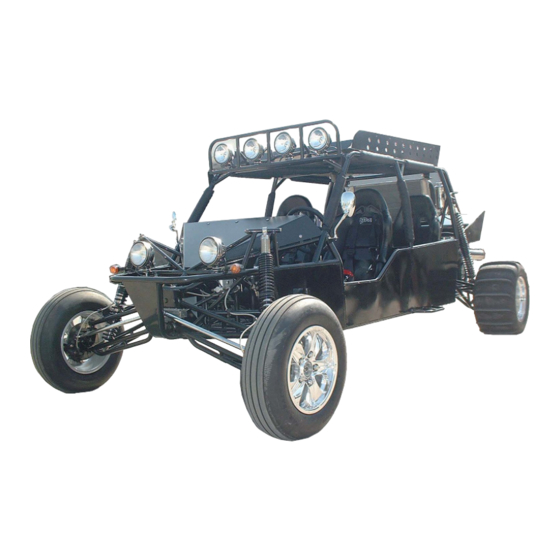
Owner's manual
JNSZ1600QL
Parts manual
READ THIS MANUAL CAREFULLY
IT CONTAINS IMPORTANT SAFETY INFORMATION.
MINIMUM
RECOMMENDED
OPERATOR AG
FOR OFF-ROAD USE ONLY
This vehicle is designed and manufactured for off-road use only.
USA only;
It does not confirm to federal motor vehicle safety standards, and operation on public streets, roads, or
highways is illegal
0
Advertisement
Chapters
Table of Contents

Related Manuals for Joyner JNSZ1600QL


Summary of Contents for Joyner JNSZ1600QL
-
Page 1: Parts Manual
Owner’s manual JNSZ1600QL Parts manual READ THIS MANUAL CAREFULLY IT CONTAINS IMPORTANT SAFETY INFORMATION. MINIMUM RECOMMENDED OPERATOR AG FOR OFF-ROAD USE ONLY This vehicle is designed and manufactured for off-road use only. USA only; It does not confirm to federal motor vehicle safety standards, and operation on public streets, roads, or... - Page 2 This warranty does not apply to any part, which in opinion of sold was defective because of improper maintenance, improper assembly, alterations, abuse, negligence or accident. Should warranty service be required on your JNSZ1600QL during the 90 days warranty period, please contact your nearest authorized dealer for repairs.
-
Page 3: Table Of Contents
CONTENTS OWNER’S MANUAL Page 1. FOREWORD-----------------------------------------------------------------------------------------------3 2. A FEW WORDS ABOUT SAFETY--------------------------------------------------------------------4 3. IMPORTANT SAFETY INFORMATION------------------------------------------------------------5 4. SAFETY LABELS-----------------------------------------------------------------------------------------7 5. ARE YOU READY TO DRIVE? -----------------------------------------------------------------------8 6. IS YOUR VEHICLE READY TO DRIVE? -------------------------------------------------------- 10 7. SAFE DRIVING PRECAUTIONS ------------------------------------------------------------------- 12 8. -
Page 4: Foreword
Preventative maintenance is extremely important to the longevity of your ATV. JOYNER believes in conservation and protection of earth’s natural resources. To that end, we encourage every vehicle owner to recycle, trade in, or properly dispose of, as appropriate, used motor oil, coolant, and other fluids, batteries, and tires. -
Page 5: A Few Words About Safety
A NEW WORDS ABOUT SAFETY In order to keep everyone safe, you must take responsibility for the safe operation of your ATV. To help you make informed decisions about safety, we have provided operating procedures and other information on labels and in this manual. This information alerts you to potential hazards that could hurt you or others. -
Page 6: Important Safety Information
IMPORTANT SAFETY INFORMATION Your ATV will provide you with many years of service and pleasure. Providing you take responsibility for your own safety and understand the challenges you can meet while driving. There is a lot you can do to protect yourself when you drive. You’ll find many helpful recommendations throughout this manual. - Page 7 IMPORTANT SAFETY INFORMATION Keep away from moving parts of the ATV The operator of the ATV should never place their hands or other parts of their body near any moving part of the ATV. Failure to adhere to this warning will cause physical harm to your body. Skidding or Sliding The terrain surface can be a major factor affecting turns, Skidding a turn is more likely to occur on slippery surfaces such as snow, ice, mud and loose gravel.
-
Page 8: Safetylabels
SAFETYLABELS This section presents some of the most important information and recommendations to help you drive your ATV safely, please take a few moments to read these pages. The labels are considered permanent parts of the ATV. If a label comes off or becomes hard to read, contact your dealer for warning labels replacements. -
Page 9: Are You Ready To Drive
ARE YOU READY TO DRIVE? Before each drive, you need to make sure you and your ATV are both ready to drive. To help get you prepared, this section discusses how to evaluate your driving readiness, what items you should check on your ATV, and adjustments to make for your comfort, convenience, or safety. - Page 10 ARE YOU READY TO DRIVE? Additional Driving Gear In addition to a helmet and eye protection, we also recommend: Sturdy off-road motorcycle boots to help protect your feet, ankles, and lower legs. ■ Off-road motorcycle gloves to help protect your hands. ■...
-
Page 11: Is Your Vehicle Ready To Drive
IS YOUR VEHICLE READY TO DRIVE? Before each drive, it is important to inspect your ATV and make sure any problems you find are corrected. A pre-drive inspection is a must, not only for safety, but because having a breakdown, or even a flat tire, can be a major inconvenience. - Page 12 IS YOUR VEHICLE READY TO DRIVE? sure there is no brake fluid leakage. Engine Stop ■ When engine is running, turn the switch key counterclockwise. Make sure engine stops. Steering Wheel ■ Check that the wheels turn properly as you turn the steering wheel. Cable ■...
-
Page 13: Safe Driving Precautions
SAFE DRIVING PRECAUTIONS Control Speed Driving at excessive speed increases the chance of an accident. In choosing a proper speed, you need to consider the capability of your ATV, the terrain, visibility and other operating conditions, plus your own skills and experience. Operating this ATV at excessive speeds increases your changes of losing control of the ATV, which can result in an accident. -
Page 14: Specifications
SPECIFICATIONS DIMENSIONS Overall Length---------------------------------------------------------------------------------------162.4in. (4125mm) Overall Width ---------------------------------------------------------------------------------------88.5 in. (2250mm) Overall Height ----------------------------------------------------------------------------------------71.7 in. (1822mm) Wheelbase ---------------------------------------------------------------------------------------------123.6 in. (3140mm) Front Track ------------------------------------------------------------------------------------------- 68.8 in. (1748mm) Rear Track --------------------------------------------------------------------------------------------72.4in. (1840mm) Ground Clearance ------------------------------------------------------------------------------------ 14.2in. (360mm) ENGINE Type ---------------------------------------------------------------------------------4-Bore,4-Stroke, Liquid-cooled Bore x Stroke --------------------------------------------------------------------------------------------79.94mm×79.52mm Displacement ------------------------------------------------------------------------------------------------------1596 cc Compression ratio ------------------------------------------------------------------------------------------------ 9 .75:1 Carburetor ---------------------------------------------------------------------------------------------Electric Fuel Injection... -
Page 15: Operations
OPERATION A. Operation controls WARNING-Do not attempt to start or operate the engine until completely familiar with the location and use of each control necessary to operate this vehicle. The operator must know how to stop this machine before starting and driving it. a. - Page 16 OPERATION d. Start engine 1. Press the clutch pedal down, put the shift lever in neutral I nsert the key into the ignition-switch 、 Fig. 2 If the engine is cold; 1. Press down the clutch pedal 2. Turn the key clockwise to the “on” position. Release the key and the clutch pedal when the engine starts.
- Page 17 Before you start the engine, check that the parking brake is engaged, and the gear shift lever is in neutral. Trying to start the engine in gear may damage the starter motor, clutch or gearbox. Release the key at once if the engine starts. Holding the key in start position when the engine is running will cause damage to the starter motor.
- Page 18 OPERATION 11. Check Brake Light. Check for proper operation. 12. Check Wheels. Check for tightness of wheel nuts and axle nuts; check that axle nuts are secured by cotter pins. 13. Check Steering. Check for free operation and for any unusual looseness in any area. Always follow rules for safe operation and wear a helmet.
- Page 19 OPERATION E. Parking Adjustment(See Fig. 4 ) Pull the park brake lever up so that the unit can engage park brake. a. To release the unit, press button on front end of parking lever then push the parking lever to the bottom.
-
Page 20: Starting
Fig. 7 G. Break-in The first month is most important in the life of your vehicle. Proper operation during this break-in period will help assure maximum life and performance from your new vehicle. The following guidelines explain proper break-in procedures. 1. -
Page 21: Service Instructions
SERVICE INSTRUCTIONS Service Air Filter . . . . Service air filter every 80 hours NOTE: Service more often under dusty conditions. Fig.8 a. Remove filter cover(See Fig. 8) b. Check the filter cover and the air filter, if the filter cover and the air filter is dusty, please clear the filter cover and replace with a new air filter. - Page 22 SERVICE INSTRUCTIONS Fig. 11 Fig. 12 a. With the engine warm, put the vehicle on the level ground. b. Shut down the engine, put a collecting oil plate under the engine oil outlet. Loosen the oil outlet plug in the warm engine. Let the engine oil out fully (see Fig. 9). c.
- Page 23 SERVICE INSTRUCTIONS C. Transmission lubrication You must change the oil in the transmission after the first 5 hours of operating of your new engine and after 10 hours of use thereafter. That will insure proper lubrication of internal parts and prevent costly repairs due to excessive wear.
- Page 24 SERVICE INSTRUCTIONS a. Put the vehicle on the level ground. b. Shut down the engine, put a collecting oil plate under the transmission oil outlet. Loosen the oil outlet plug in the warm engine. Let the transmission oil out fully (see Fig. 14 1 5).
- Page 25 SERVICE INSTRUCTIONS 4. Increase the engine rev’s a few times 5. Repeat 2,3,4 till the coolant is at neck and no bubbles come up. 6. Refit the coolant cap, turn it clockwise and tighten it 7. Turn the reserve coolant case cap counterclockwise and open the cap (see Fig. 17). 8.
-
Page 26: Spark Plug
SERVICE INSTRUCTIONS Fig.20 G. Cleaning Instructions Keep your kart clean. With a clean rag, wipe off any dirt and oil from around controls. Wipe off any spilled fuel and oil. Keep the engine clean of foreign object and be sure to check that air intake fan is free of debris for proper cooling. -
Page 27: Repair
REPAIR Front Wheel Alignment 1. Put the vehicle on level ground. 2. The “toe-in” of the front wheels should be 0.63 inches. To check for alignment, measure distance A and B between the centerline (CL) of the wheels. The proper toe-in dimension A should be 0.63 inches greater than dimension B. -
Page 28: About Engine
About engine A. precaution a. strictly observe all requirements and specifications in this manual. b. Check the earth polarity of accumulator. this gasoline engine adopts negative earth. c. Grinding in must be conducted when using a new gasoline engine. d. When gasoline engine is running, your head, hand, cloth, tool and other things should be strictly forbidden to approach the running fan and pump belt. -
Page 29: Periodical Check And Service
PERIODICAL CHECK AND SERVICES The maintenance intervals in the following table are based upon average driving conditions. Driving in unusually dusty areas, require more frequent servicing. Time of service Initial Monthly Quarterly Yearly Item service Engine 1. Tighten bolts on engine. 2. -
Page 30: Engine Maintenance And Service
ENGINE MAINTENANCE AND SERVICE Introduction…………………………………………………………………………………………...….30 Engine configuration view and sectional view……………………… ………………………………..31 Main engine technical indexes and operation parameters……………………………….……….……32 Engine structural features……………………………………………………………………………..35 Engine maintenance..……………………………………………………………………….....…….36 Engine removal and assembly procedure……………………………………………………………..39 [1] Positioning no.1 cylinder top dead center (compression) …………………………………………39 [2] Upper and lower timing gear cover assemblies removal and installation………………………..40 [3] Crankshaft pulley removal and installation………………………………………………………..41 [4] Valve cover and seal gasket removal and installation……………………………………………..42 [5] Timing belt removal, installation and adjustment………………………………………………..43... -
Page 31: Introduction
Introduction CAC480 series vehicle gasoline engines, which are the products introduced from Ford (Britain) corporation CVH production line, are made by Anhui Chery automobile Corp. Products are made up of carburetor type, single-point electric control fuel injection type and electric control fuel injection type, which may meet the requirements for different performance and emission. -
Page 32: Engine Configuration View And Sectional View
ENGINE CONFIGURATION VIEW AND SECTIONAL VIEW Fig.22... - Page 33 Fig.23 Fig.24 Fig.25 1.Temperature regulator seat assembly 11. Camshaft thrust plate 2.Temperature regulator seat 12. Camshaft timing gear...
-
Page 34: Main Engine Technical Indexes And Operation Parameters
3. Distributor 13. Timing belt 4. Camshaft assembly 14. Upper\ lower timing gear cap assembly 5. Fuel pump assembly 15. Water pump assembly 6. Air intake manifold assembly 16. Camshaft timing gear 7. Fuel pressure switch 17. Tensioner pulley assembly 8. - Page 35 Emission(Idling)CO 1.2% Weight (kg) Overall dimensions (Length * width * highness) 6 10 6 50 (mm) × × Ignition angle at idle (Crankshaft angle ° ± ° B efore top dead center) , Valve timing(Crankshaft angle) Intake valve opened Before top dead center18 °...
-
Page 36: Engine Structural Features
Fan speed r/min s peed 1500 Ⅰ s peed 2800 Ⅱ Air filter 1GD129607G Engine structural features 1.Cylinder block : Made from gray cast iron. Without bibcock. Without cylinder liner.5 main bearing seats. Main Intermediate bearing anti-thrust. Main bearing caps are retained by spigot. Main bearing bolts of 12.9 grade. - Page 37 12.Hydraulic lifting rod : : : : T he surface contacting cam is quenched. The contact face with rocker arm is made of low carbon steel. Surface carbonitriding , B oth contact face are circular-arc. 13.Intake valve seat : : : : I t is made of alloy cast iron.
- Page 38 micro-circulation tube. 29.Carburetor : : : : P ierbort 2E3 carburetor. Throttle valve body for 480M 30MM12 Imported part. 30.Spark plug : : : : K 7RTC 31.Non-contact distributor : : : : Driven by the rear end of camshaft ,...
-
Page 39: Engine Maintenance
Engine maintenance: : : : Daily maintenance ——Check lubricant level ——Check coolant level ——Check bolt for loosing ——Check for leaking (oil, water, air) Per8000km ——Replace engine oil and oil filter ——Clean air filter , c heck air intake tube for cracking ——... - Page 40 480Contents and intervals for Constant maintenance 1 000km × Replace engine oil ☆ ☆ ☆ ☆ ☆ ☆ Replace oil filter ☆ ☆ ☆ ☆ ☆ ☆ Clean air filter core ☆ ☆ ☆ ☆ ☆ ☆ Check spark plugs ☆...
-
Page 41: Engine Removal And Assembly Procedure
Engine removal and assembly procedure . Positioning no.1 cylinder top dead center (compression) 【 【 】 】 【 【 】 】 Fig.26 ——Remove two M6 × 5 5 flange-shaped bolts, remove upper timing gear cover. ——Install a wrench on crankshaft pulley bolt, rotate crankshaft Clockwise (viewed from the direction of pulley) until the TDC notch on crankshaft pulley aligns with the TDC mark (0) on timing gear cover. -
Page 42: Upper And Lower Timing Gear Cover Assemblies Removal And Installation
Fig.28 Rotate crankshaft, aligning the TDC mark on the crankshaft gear shaft with the TDC mark on the oil pump case. Check whether the TDC mark on camshaft gear aligns with the TDC mark on the front end of , cylinder head. -
Page 43: Crankshaft Pulley Removal And Installation
——Remove seal gasket and shot nail from upper timing gear cover. ——Remove crankshaft pulley. ——Loosen and remove 2 bolts for lower timing gear cover assembly. ——Remove lower timing gear cover and seal gasket assembly. ——Remove shot nail and seal gasket from lower timing gear cover. Installation :... -
Page 44: Valve Cover And Seal Gasket Removal And Installation
Fig.31 Installation : — —Clean pulley and crankshaft journal , r emove the oil in pulley groove . ——Install pulley on crankshaft journal, aligning keyway with semicircular key. ——Slip cushion block onto bolts and finger screw in. ——Block flywheel ring gear with screwdriver, preventing crankshaft from turning. ——Tighten bolts to 100—115Nm. - Page 45 Fig.33 Removal : — —Remove 9 bolts and butterfly gasket. ——Remove valve cover and seal gasket assembly. ——Remove seal gasket. Fig.34 Fig.35 : Installation — —Clean cylinder head and valve cover contacting surface. ——Push the wedge of valve cover seal gasket into appropriate valve cover groove, integrating valve cover with seal gasket.
-
Page 46: Timing Belt Removal, Installation And Adjustment
Step 2 : T ighten to 8.0—10.0Nm . Timing belt removal, installation and adjustment 【 】 : Removal — —Rotate crankshaft to no.1 cylinder compression TDC. , ——Loosen 2 tension pulley mounting bolt (as arrow indicated in diagram) p ush tension pulley aside with a large screwdriver. -
Page 47: Tension Pulley, Crankshaft Gear And Camshaft Gear Removal, Check And Installation
Fig.38 Fig.39 : , , Note W ith belt removed d on't turn gear excessively o r piston head and valve may be damaged for contacting. ——If belt need to be reused , c heck for improper wear ,delaminate crack (particularly at the :... - Page 48 2. Camshaft gear. : Removal — —Rotate crankshaft to no.1 cylinder compression TDC ——Remove belt. ——Insert a lever into one of the camshaft gear holes to block camshaft , t hen loosen gear bolt and remove bolt and cushion block. Note :...
-
Page 49: Camshaft Oil Seal Removal And Installation
Fig.41 Removal : — —Block crankshaft and remove belt. ——Pull out crankshaft gear with puller or 2 large screwdrivers , t hen remove semicircular key. Installation : ——Check gear tooth for wear, pitting or scratch. ——Install semicircular key , p rotrusion should be 1.392—1.739mm. ——Install shim with curved face side forward. -
Page 50: Valve Mechanism And Cylinder Head Removal, Check And Installation
Fig.42 Fig.43 Removal — —Remove camshaft gear. ——Note the direction of oil seal installation, pry out oil seal : from the oil seal hole in cylinder head be sure not damage the oil seal hole. Installation ——Clean the , : oil seal hole in cylinder head ,apply clean engine oil on oil seal edge and camshaft oil seal journal ,... - Page 51 1.Valve mechanism for 480 engine : : : : Fig.44 2.Cylinder cover bolts removal and cylinder head assembly installation F i g . 4 5 F i g . 4 6...
- Page 52 Fig.47 Fig.48(A dowel B cyclinder head gasket) : Cylinder head bolts removal — —Rotate camshaft until keyway is rightly upside. ——Loosen cylinder cover bolts in order as specified in diagram. ——Note : C ylinder cover bolts must be replaced after removed and are not permitted to reuse.
- Page 53 Fig.49 Fig.50 F i g . 5 1 ——Install new cylinder head bolts and washers into bolt holes, screw in by hand. ——Tighten cylinder head bolts in four steps in the order as diagram specified. Step 1 : T ighten to 20—40Nm Step :...
- Page 54 Fig.52 Fig.53...
-
Page 55: Installation
Fig.54 Fig.55 : , Installation — —Check rocker arm contact surface for abnormal wear r eplace rocker arm if necessary. ——Pull rocker arm support washers onto rocker arm double end studs. ——Lubricate rocker arms and rocker arm supports with engine oil. ,... - Page 56 Hydraulic lifting rod installation : — —Hydraulic lifting rod size : : Unit Cylinder head Lifting rod Grade lifting rod hole clearance outside diameter diameter Standard Φ22.200—Φ22.212 0.023—0.065 Φ22.25 0 .015 ± Φ22.454—Φ22.466 0.023—0.065 Φ22.50 0 .015 ± ——Apply hyperbolical gear lubricant or engine oil on lifting rod, lifting rod outside diameter and lifting rod ends, install lifting rods in original order into the holes in the cylinder head.
- Page 57 Note : 4 80 camshaft may only be used on 480M. Fig.60 Fig.61 Fig.62 : ——Camshaft journal and cylinder head cam bearing hole size (1) Standard size mm Cylinder head Camshaft journal Camshaft journal bearing hole number diameter diameter 44.74—44.76 44.783—44.808 44.99—45.01 45.033—45.058...
- Page 58 ——Check camshaft end play , e nd play should be as specified. ——When the hydraulic lifting rod of oversize 0.25 is applied, camshaft must be selected, or the hydraulic lifting rod may be stuck. Fig.63 Fig.64 Fig.65 Fig.66 Valve, valve spring, valve oil seal, spring seat assembly removal and installation :...
- Page 59 Intake Exhaust valve valve Grade Valve Valve Valve Valve guide hole guide hole stem Clearance stem Clearance diameter diameter diameter diameter 8.043+0 8.017+0 Standard 8.063-8.094 8.063-8.094 -0.018 -0.018 0.02-0.069 0.046-0.095 8.463-8.494 8.443+0 8.417+0 Oversize0.4 8.463-8.494 -0.018 -0.018...
- Page 60 Fig.67 Fig.68 Fig.69 Fig.70 ——Measure valve spring free length and spring force: Compression Spring free Spring load (N) (mm) length L1=37.084 L2=27.7 892.7 L0=47.2 L3=27.0 ——Grinding the valve and the valve seat with the valve conical angle (Intake valve and exhaust valve): 44 °...
- Page 61 lock piece groove with a special compression tool. Then put the lock pieces into it and release the compression tool slowly and remove the tool. ——Put the cylinder head on a wood lump after all lock pieces are assembled. And tap the small head of the valve stem with a plastic or copper hammer to fit for the valve mechanism.
- Page 62 The size of valve guide and valve guide hole The valve The diameter Press fit Level guide of ylinder clearance hole head tube hole 13.555 0 Standard 13.481-13.519 -0.01 14.305 0 Oversize 14.231-14.269 0.026-0.07 -0.01 14.505 0 Oversize 14.481-14.519 -0.01 .
- Page 63 ——Measure the diameter of cylinder bore. Unit: mm 480 cylinder bore 79.94—79.95 79.95—79.96 Factory group 79.96—79.97 79.97—79.98 80.23—80.24 Factory 80.24—80.25 repair 80.25—80.26 Standard 79.965—77.975 mainte Oversize 80.245—80.255 nance 0.29 Oversize 80.466—80.475 Fig.75 Fig.76 ——Grind the cylinder bore with the service gauge and the figured twins angle is 50 °...
- Page 64 Oversize 77.71—77.735 80.43—80.455 80.465—80.475...
- Page 65 * 480M piston should be applied on 480E engine ——Measure the diameter. of the hole of piston pin Unit : diameter of the piston pin hole White 20.630—20.633 20.633—20.636 Blue 20.636—20.639 : ——Measure the diameter of piston pin Unit diameter of the piston pin hole White 20.622—20.625...
- Page 66 Fig.78 Fig.79 Fig80 ——Check and make sure that the oil injection hole of the connecting rod large end is not blocked. The outside diameter is φ 1 mm. Installation: ——Need not to divide into groups for the piston weight, piston pin holes and the accessory piston skirt.
- Page 67 outside cut section should be put down and remember not to the contrary. Firstly the oil controlling ring, then the second compression ring, and finally the first compression ring. As assembling the ring, its maximum tension should be inferior to the diameter of the cylinder(+1. 65mm), or the ring would be deformed and broken.
- Page 68 Screw in 6 new bolts by hand. Bolts should have sealant on them. Tightening torque is 82—92Nm. Fig.82 Fig.83 Fig.84 Fig.85 Fig.86 : : : : 2). The removal and installation of carrier assembly of the real oil seal: Removal ——Remove 4 bolts (as arrow indicates).
- Page 69 ——Align rear oil seal carrier hole with the part number side of oil seal outward. Press oil seal into rear oil seal carrier with vise.. The magnitude of interference for real oil seal and carrier hole is 0.26—0.50mm. ——Install new sealing gasket of real oil seal carrier. ——Install real oil seal carrier assembly.
- Page 70 Fig.87 Fig.88 Fig.89 Remove main bearing bolt. Take out the main bearing cap Fig.90 Fig.91 Fig.92 carefully. Arrange them according to the sequence. Read the bearing clearance according to the proportion stated in the cover of plastic clearance gauge. Check the bearing clearance from the third main bearing and extending to the two sides.
- Page 71 The thickness of The diameter of connecting connecting rod Level rod journalφ bushing Standard 47.89—47.91 1.480—1.487 47.89—47.91 1.492—1.499 n dersize 0.025 47.64—47.66 1.605—1.612 0.25 U n d e r s i z e 47.39—47.41 1.730—1.737 U n d e r s i z e 47.14—47.16 1.855—1.862 0.75...
- Page 72 Fig.93 : : —the size of crankshaft thrust, thrust washer and cylinder block thrust U nit The size of The size of The thickness of cylinder body Level crankshaft thrust thrust washer thrust Standard 28.825—28.875 0 .03 2.326 0 .025 ±...
- Page 73 Drive the semicircular key into key groove lightly. The magnitude of interference for key and key groove is 0.00—0.051mm 。 A fter the semicircular key is installed, check the protrusion height. It should be 1.392—1.739mm. ——Crankshaft thrust washers are two pieces. They are only installed on the front and back thrust surface of cylinder block.
-
Page 74: Engine Oiling System
. Engine oiling system: 【 【 】 】 【 【 】 】 1). The description of the oiling system: Through oil collector (2), the rotary oil pump (1) which is installed in the front end of crankshaft draws oil from oil pan (3) and pressurizes. The pressure oil comes into the full flow type oil filter through the assistant oil passage (4) on the left of cylinder body (viewed from the front). - Page 75 : : : : 2) The removal and installation of oil pan Removal : — —Loosen drain plug and drain oil ——Loosen eighteen M6 × 2 0 bolts ——Take out the sealing gasket of oil pan ——Check if the left and right reinforced plates are still clipped on the back face of oil pan flange face Fig.98 Fig.99...
- Page 76 ——Replace the sealing gasket of drain plug. Screw in the drain plug by hand and tighten to 21—25Nm.
- Page 77 The removal and installation of oil collector assembly Removal : — —Loosen locknut of oil collector assembly and take out the nut and flat washer 。 ——Loosen carrier bolts and take out the bolts ——Loosen flange face bolt of oil collector (two ) and take out the two bolts with spring washers Installation :...
- Page 78 Fig.103 Fig.104 Fig105 Fig.106 Fig.107 4. The removal and installation of oil pump with oil seal assembly removal : — —Loosen six M6 × 3 0 hexagonal flange surface bolts. Remove the bolts (as the figure indicates) ——Remove oil pump with oil seal assembly ——Pry out the front oil seal of crankshaft by screwdriver or chisel.
- Page 79 Fig.108 Fig.109 Fig.110 Fig.111 ——Check the clearance between outer rotor of oil pump and case bore of oil pump. The clearance between outer rotor of oil pump and case bore of oil pump should be 0.06—0.19mm. ——Check the radial clearance between inner rotor and outer rotor of oil pump. The radial clearance between inner rotor and outer rotor of oil pump should be 0.05—0.18mm.
- Page 80 Fig.112 Fig.113 Fig.114 Fig.115 ——If relief valve spring is not to specification, it must be replaced. Installation : ——Install the outer and inner rotor into the oil pump house ensuring the installation mark of outer and inner rotor upward. ——Install oil pump cover on oil pump. Tighten seven chamfer head screws. Tightening torque is 7-10Nm.
- Page 81 ——Wrap a plastic tape on the oil seal journal of crankshaft avoiding to damage the edge of front crankshaft oil seal. ——Apply engine oil on the edge of front crankshaft oil seal. Press the oil seal in place using appropriate socket or sleeve and crankshaft pulley and pulley bolt and washers.
-
Page 82: Engine Cooling System
Fig.118 . Engine cooling system 【 【 【 【 】 】 】 】 1) Description for cooling system The cooling system is of pressure system. It includes water pump driven by timing belt, crosscurrent radiator, expansion tank, pressure cap, thermostat and electric fan, fan shroud. - Page 83 : : : : —cooling system parameters Total system capacity (L)8 electric fan water pump Engine capacity (L) 3.3 diameter. 280mm diameter of impeller 72mm ∶ radiator capacity (L) 2.1 blade quantity 6 speed ratio 1.053 expansion tank capacity(L)0.4 operating voltage 9 -...
- Page 84 (3) Start engine and keep idling., warm engine to normal working temperature and stop engine cooling down. (4) Drain water (5) Repeat step (2)—(4) until the water drained is the same as clean water. (6) If the previous coolant application and replacement is not to specification, do some cleaning as the following method: a.
- Page 85 Fig.119 Fig.120 2) The removal and installation of water pump assembly ——The structure of water pump assembly —water pump case —water pump impeller —water pump gear —water pump bearing —water pump seal (ceramics—black lead) Removal : — —Loosen and remove four bolts from the front end of cylinder block ——Remove water pump assembly ——Remove sealing gasket of water pump :...
- Page 86 ——Install the water pump assembly inside the cylinder block and screw in four retaining bolt by hand, then tighten to 7.0—10.0Nm. Note: The water pump assembly may not be serviced. When water seal or bearing is damaged, the water pump assembly should be replaced 3) The removal and installation of thermostat seat with thermostat assembly Fig.121 Fig.122...
- Page 87 ——Loosen three M6 × 4 0 bolts and remove them ——Remove thermostat seat with thermostat assembly ——Pry out spring clip by chisel or screwdriver ——Take out the thermostat ——Take out sealing gasket ——Remove sealing gasket of thermostat seat Measure the opening temperature of thermostat in hot water. Fig.125 ——Clip the thermostat seat, and put the rubber seal ring into the thermostat hole.
- Page 88 sealant 243 onto the bolt threads. Finger screw in and tighten to 7.0-10.0Nm. . The intake and exhaust system of the engine 【 【 【 【 】 】 】 】 1. Description for the intake and exhaust system of carburetor engine. The intake system of Carburetor Engine 480 includes: air filter, Intake hose, Guide cover, Carburetor, Intake hose, Intake air preheating hose of Positive Crankcase Ventilation (...
- Page 89 Fig.127 intake and exhaust system schematic drawing of engine 480M The Intake System of Engine 480M includes: air filter, Intake Hose, Guide Cover, Throttle Valve, Intake Manifold, Intake air preheating hose of Positive Crankcase Ventilation ( P CV ) and so on. ——Air filter type is 1GD 129 607G, and its basic parameters are as follows: Filtering area: 100cm2 nominal air flow(L): 600 ±...
- Page 90 Fig.128 composing of intake manifold assembly of carburetor engine Fig.129 composing of intake manifold assemble of electric injection engine The intake manifold ‘s air may be preheated by the electrical heater as well as by coolant. As the coolant’s temperature is lower than 60 °...
- Page 91 ——Remove the intake manifold. ——Remove the intake manifold sealing gasket. ——Remove six studs with equal length using two M8 nuts. Assembly: ——Apply lotite sealant 201 on the cylinder head bolt threads and screw six studs into the cylinder head. ——Assemble the new sealing gasket onto the studs. ——Install the intake manifold assembly.
- Page 92 4. The removal and assembly for the exhaust manifold, heat insulation cover and rear lifting lug: - × Removal: L oose and remove the M12 2 5 allen screw, and remove the rear lug . - L oose and remove two M8 ×...
- Page 93 2. Description for PCV system of 480M engine Fig.132 Fig.133 2.1 Description of PCV system. The PCV system is a closed system. The leaking air of piston goes to the rear cylinder head cover from the Crankcase through the PCV hose. PCV valve is connected to the intake manifold. Meantime, a Ф...
- Page 94 . Fuel supply system of the carburetor engine 【 【 【 【 】 】 】 】 1. Fuel supply system of the carburetor engine. Fig.134 Fig.135 1.1 Description of the fuel supply system. The fuel in the tank flows into oil filter pumped by the fuel pump and goes into carburetor after being filtered through fuel pump.
- Page 95 Fig.136 1.2 Removal and assembly of the fuel pump: ——Remove two M8 lock nuts. ——Take out the fuel pump. ——Remove the fuel pump sealing gasket. ——pull out the push rod. Fig.137 Fig.138 ——Remove the studs of same length. Assembly: ——Submerge the push rod into the engine oil or pour engine oil into the rod’s hole of the cylinder head and install the push rod into the hole.
- Page 96 Fig.139 Installation: Use studs, nuts, and washers to connect the transition flange with intake manifold. Screw the studs into intake manifold and tighten them with nuts. Tightening torque is 8-10Nm. Adjustment: The carburetor adjustment mentioned in this introduction only specifies the idle speed adjustment and CO adjustment.
- Page 97 Fig.142 schematic drawing of engine 480M fuel system ——Adjustment of Peirburg 2E3 carburetor: Idle speed adjustment: Rotating the screw inward will increase idle speed. Rotating the screw outward will decrease idle speed. CO adjustment: Rotating the CO screw inward will enrich the mixture. Rotating the screw outward will make the mixture lean.
- Page 98 ——It is forbidden to ground the power supply wire while the alternator is under working condition, the wiring harness will be burn away. ——While the alternator is under working condition, it is not allowed to disconnect the alternator connector B from battery, or the voltage caused will damage the transistor or other elements. ——To test the diodes, the voltage applied should be not beyond 40V.
- Page 99 Fig.145 The JFZ1913—4 alternator for independent assembly. Fig.146 Fig.147 The JFZ18D13 ZB alternator for independent assembly Fig148 Fig.149 The alternator bracket for independent assembly 2. Starter Rated output: 0.95kW Speed range: 1000-1800r/min Voltage: Type: QDY1258 SD6RA78 ——The flywheel gear ring for vehicle and the one for independent engine assembly is different and also the starter gear modulus is different, so different starters need to be applied.
- Page 100 Fig. 150 Fig. 151 Fig. 152 Ignition module assembly Fig. 153 ——The left chart is QDY1258 ——When checking starter, you should clean carbon brush. Its surface should not have dust and calibrator, and the brush can move freely in the carbon brush carrier. Change them if the brush and carrier are damaged severely.
- Page 101 Fig.154 Fig.155 × ——Loosen and remove two M6 2 0 bolts. ——Remove the distributor. ——Remove the distributor’s “O “seal. Assembly: ——Insure that the engine is set correctly with No.1 Cylinder at TDC. ——Install new “O” seal. ——Rotate distributor to align the lug with the No. 1 cylinder TDC mark on the distributor flange. Install the distributor inserting the lug into the camshaft groove.
- Page 102 Fig.157 Fig.158 Carburetor engine faults, causes and corrections 1. Engine does not run during starting: Cause Correction (1). Battery wires are loose or corroded Reconnect or replace the wires (2). Battery is discharged or damaged Recharge or replace the battery (3).
- Page 103 (9). Fuel pump is damaged Replace pump (10). Carburetor float chamber needle valve is binding or oil strainer is blocked Check, service and clean (11). Idle cut-off valve does not open Check circuit and solenoid 3. Difficult to start for engine when temperature is low: Cause Correction (1).
- Page 104 (4). Mail measuring orifice blocked Check and clean mail measuring orifice (5). Idle cut-off valve damaged and not open Check circuit and solenoid (6). Idle speed too low Adjust engine idle speed (7). Idle speed fuel outlet port or transition port blocked Check and clean 7.Rough engine idle speed Cause...
- Page 105 (10). PCV hose loose, leaking, or damaged Connect or replace 9. Engine Stalls within operation speed range Cause Correction (1 ). Fuel filter blocked Replace fuel filter ( 2). Fuel pump working incorrectly or low output pressure Replace fuel pump (3 ).
- Page 106 12. Engine power is not enough. Cause Correction (1). Incorrect Ignition timing Check or adjust distributor (2). Incorrect Timing belt assembly or Adjust ‘teeth’belt tension or tension incorrect belt tension pulley. (3). Carburetor float chamber level too low or Check and clean carburetor float needle fuel intake strainer blocked valve and strainer (4).
- Page 107 (6). Oil collector blocked or loose Clean or replace or tighten 15. Engine self ignited. Cause Correction (1). Too high idle speed, too lean mixture or Adjust idle speed or fast idle boost fast idle gear out of work (2). Incorrect fuel grade Use fuel of correct grade (3).
- Page 108 a.Connecting rod bushing worn out (generally severe Check and service knocking, may be relieved under load.) b.Main bearing half shell worn out (booming or Check and service knocking noise, may be relieved under load) c. Piston knocking (apparent with engine cold) Check and service d.
- Page 109 (7). cylinder compression pressure decreases check engine (8). Incorrect ignition timing adjust ignition timing (9). Too low tire pressure inflate the tire...
-
Page 110: Summarize
CAC480M Engine’s single port injection system [ [ [ [ 1] ] ] ] . Summarize The system, referred as “ λ S peed Density”type (running speed, air density, mixture control), is designed to perform the control for injection and distributorless ignition. According to the following figure (figure 159) of Single Port Injection System, three basic parts are included as the following: 1. -
Page 111: Operation Principle
21. λ s ensor 22. Tachometer 23. IAW system warning indicator [ [ [ [ 2] ] ] ] . Operation principle: Single Port Injection System is applied on the vehicle equipped with 3 way catalyst converter .the system insures air/fuel mixture ratio in the vicinity of the ideal air/fuel ratio. The ideal air/fuel ratio is important for catalyst converter to work normally. - Page 112 doesn’t work. · s tepper motor, fuel injector, and fuel pump circuits are shorted · h igh pressure ignition coil, fuel vapor recirculation solenoid is shorted or opened. Main parameters are shown according to the requirements: speed, water temperature, injection time, ignition advance, intake manifold pressure, throttle valve position, battery voltage, stepper motor position (steps).
- Page 113 Fig.161 According to λ s ensor signal, ECU will automatically revise C0 parameter(close loop). When λ s ensor fails, ECU may work under open loop. 2. Single Port Injection System Throttle Valve “30MM12” “30MM12”throttle valve is one of the main system parts. Most sensors and actuators are assembled in the throttle valve.
- Page 114 Fig.162 The following accessories and engine air filter are installed on the upper body of throttle valve. · f uel system pipe and fuel return pipe · f uel pressure regulator · b ottom-supplying fuel injector IWM · i ntake air temperature sensor.
- Page 115 1. Socket head regulator screw 5. Spring 2. Spring 6. Sealing valve 3. Fuel output pipe 7. Diaphragm 4. Fuel return pipe Fig.163 IWM523 fuel injector applied in the system is of the shortened type of the first generation. It is entirely made of stainless steel and superior in the function.
- Page 116 -Synchronous (for normal operation). Injector opening corresponds with every TDC. -Not synchronous (for idling, cut-off, low speed, start operation). Injector opening is completely controlled by time and not related to TDC signal. ECU has a basic current control circuit to control fuel injector. The circuit produces the maximal current (signal) at the first control order speed up the opening of injector.
- Page 117 output signal and throttle valve opening ange. Fig.166 · S ensor component is consisted of a potentiometer. The slipping ruler of potentiometer is driven directly by accelerator pedal which is proportional with throttle valve opening. · t he potentiometer is inserted into plastic case with two baffles on the bracket.
- Page 118 again. Notice: Don’t adjust the potentiometer bolt if it does not return to the specified value of throttle valve opening angle. The potentiometer should be replaced because it fails. ——Engine idle speed actuator (idle control stepper motor) Idle control stepper motor is a position actuator of high precision and high distinguishability ( +/-50r/min) for controlling idle speed.
- Page 119 The fuel pump signal is timed. Once ignition switch is on and engine is not started, there will be a fuel pump signal within 10 seconds. Under the engine running and starting conditions, the fuel pump signal will not change. Fig.168 Fig.169 3.2 fuel filter...
- Page 120 —— Generate signal for the RPM counter —— Detect two missed teeth to confirm the synchronous position every engine revolution Without the signal or the corresponding synchronous signal (60—2 signals/revolution) , ECU cannot be operated. Timing : Rotate the engine pulley (2) to keep cylinder 1 and cylinder 4 at TDC, i.e. the mark on the pulley (2) and the mark (3 and 4) on the timing wheel cover of engine must be matched (see figure.
- Page 121 C. Current circle for primary coil circuit a. Ignition advance angle relative to cylinder 1 TDC 4.3 absolute pressure sensor The sensing element of absolute pressure sensor is printed in a ceramic membrane by the wheatstone bridge silk PCB. One side of the membrane is absolute reference vacuum and the other side is actual vacuum of the intake manifold.
- Page 122 Fig.173 Fig.174 5. Ignition advance calculation and high voltage distribution The system uses two high tension ignition coils and assigns ignition voltages directly to spark plugs by static electricity (distributorless ignition) directly. Connector and controlling triode are comprised in the ECU injection system and connected to ECU connector 1 and connector 19 .
- Page 123 R1=0.55 Ω + /-10% (20 ℃ ) R2=7400 Ω + /-10% (20 ℃ ) The base ignition advance value in the chart is determined after several adjustments according to the coolant temperature and air temperature. One filter restricts the change of two continuous TDCs, Under a specified condition, ignition advance will be compensated dynamically.
- Page 124 inserted in a protecting boot and installed in a metallic body (3). The protective casing works for the further protection and has the sensor in the exhaust manifold. Fig.176 The outside of the ceramic body (b) is exposed to the exhaust emission and the inside (a) is exposed to ambient atmosphere.
- Page 125 · W hen engine is idling with no electrical load and λ c ontrolling is functioning(close loop) , s elect LAMBDA CHECK to check if the slipping ruler on the CHEC K—UP1 diagnosis tool is in the middle of two base points . 7.
- Page 126 Fig.178 After long time since engine stopped, the temperature in the fuel tank will rise (Since the vehicle doesn’t move, the dynamic ventilation is not enough.) and the pressure in the fuel tank will rise. ——When the fuel tank is full, the multi-function valve 4 is closed. The fuel cannot flow into charcoal canister 6, therefore it doesn’t damage charcoal canister.
- Page 127 Its operation is controlled by ECU as following: · U nder the starting condition , the solenoid keeps close preventing the fuel vapor from richening the mixture until the specified engine coolant temperature is reached. · d uring engine’s running, ECU sends a square wave signal to the solenoid. The signal is used to control the fuel vapor recirculation valve by energizing or deenergizing it.
- Page 128 Fig.180 1. Battery 8. 5A 2. ECU fuse 3.1# ignition coil (cylinder 1 、 4 ) 9. Dual relays (A—ECU , B —fuel pump) 10. λ s ensor 11. Fuel pump 4. Fuel injector 12. Fuel vapor recirculation solenoid 5. 2# ignition coil (cylinder 2 、 3 ) 13.
-
Page 129: Transmission Maintenance And Service
Fig.181... -
Page 130: Wiring Diagram
[ [ [ [ 3] ] ] ] . . . . Wiring diagram 1.Injection/ignition system ECU 17.Injection system warning light (on the instrument panel) 2.Battery 20.Fuel cut-off switch 3.Ignition switch 21.A/C control unit 4.25A system fuse 22.A/C compressor relay 5.5A ECU fuse 23.A/C compressor 6.Dual relays... - Page 131 ECU I/0 function 1. Primary signal for ignition coil 16.water temperature/air/pressure sensor 2.B phrase idling actuator signal and ground wire of throttle valve 3.D phrase idling actuator signal position sensor 4.Protect relay signal 17. Main ground wire of engine 5.Without connection line 18.Fuel injector signal 6.Warning light energizing signal 19.
-
Page 132: System Service
[ [ [ [ 4] ] ] ] . System service Fig.183 (*) A/C input and signal (if euipped) Note : 1 ) All connector are viewed from the intake side of the cable 2) Cable color and number indicates the 35-pin ECU connector connection of injection system... - Page 133 Fig.184 1.Injection/ignition ECU2 diagnosis passage 12. λ s ensor 3.Speed/ TDC sensor 13.Fuel pressure regulator 4.Engine flywheel 14.Fuel injector 5.Ignition coil with dual high-pressure connector 15.Dual relays (for ECU and fuel pump) 7.Throttle valve position sensor 16.25A injection/ ignition system fuse 8.Idling speed actuator 17.5A ECU fuse 9.Water temperature sensor 18.
- Page 134 Fig.185 Fig.186 ——Engine idling speed actuator doesn’t work ——Shorted fuel injector +12V circuit ——Opened or shorted ignition coil circuit Also, monitor the following failure : ——With engine cycling start or engine working, signal wheel is not synchronous. ——Opened or shorted λ s ensor circuit ——Opened fuel pump circuit If a sensor failure (except the speed sensor/ TDC sensor) is indicated, ECU will substitute the preset value for the input data from the faulted sensor to keep engine operating.
- Page 135 —— Switch off the power supply ——Remove quick release fuel Outlet pipe and fuel return pipe Remove and reinstall filter ——Loosen and remove the filter mounting bolt from the bracket ——Remove the sealing clip of fuel pipe from the filter ——During operating, use an appropriate container to collect the fuel drained The fuel filter must be replaced every 30,000km.
- Page 136 Fig.188 [ [ [ [ 5] ] ] ] .malfaction, cause and correction Malfuction Correction Cause Fuel pump. fuel injector Check for operation by CHECK—UP1 IVM523 Tachometer Check wring, sensor resistance and installation of the Vehicle cannot start senser. sensor. Dual relays Check for function, connector connection and blown fuse.
- Page 137 1. Check for fuel supply. If fuel pressure is 1 ± 0 .1bar, it is Vehicle 1—Fuel supply ok; 2. If malfunction still remains after upper throttle body performance system (30mm12) is replaced, with a pressure regulator in the upper deteriorates throttle body, check fuel filter and fuel pipes.
-
Page 138: O Utline Drawing Of Aq015D Transmission
Outline Drawing of 5T15 Transmission... -
Page 139: Specifications
Fig.189 Specifications... -
Page 140: Structural Type And Applicability
Transmission AQ015AD Type Ratio: Z2 : Z1 Master Gearing 62:15=4.5 1st Speed 38:11=3.455 2nd Speed 37:18=2.056 3rd Speed 37:27=1.560 4th Speed 32:31=1.207 Reverse Speed 38:12=3.167 Rated Power 65KW Rated Torque 133Nm Rated Speed 6300r/min Lubricating Oil Capacity 2.0L Lubricating Oil Type API 80(75) W-90 GL-3 Gear Oil 24 Teeth, Involute Spline;... -
Page 141: Service And Operation
5T15AA is a kind of transverse mechanical transmission for middle and high grade cars, which is introduced and absorbed by our company. It has five forward speeds and a reverse speed. The forward speeds adopt the synchronizer shift, and the reverse speed uses the sliding gear meshing shift. The differential and the transmission are designed as a integral one. - Page 142 Fig.191 1 . C lutch Housing 2. Input Shaft 3. Output Shaft 4. 1st Speed Reverse Speed 6. 2nd Speed 7. 3rd Speed 8. 4th Speed 9. Transmission Case 10. Rear Case 11.Main reducing gear...
- Page 143 Dismantle and Installation of Transmission Dismantlement The transmission is put up. The drain plug on clutch side is screwed off. And at same time, the drain plug on the rear case is screwed off. The oil is drained away. Fig.192 The release lever of clutch is drawn out.
- Page 144 Fig.195 Transmission Assembly structural Resolution The plug cover of shift shaft is screwed off with special tool. The spreader spring and shift shaft assembly are taken out. Fig.196 The locking screw of reverse speed shaft is removed. Fig.197 5th speed driven gear clamping ring is removed. And 5th speed driven gear is removed with the special tool.
- Page 145 Fig.198 The retainer screw of output shaft rear bearing is screwed off. Fig.199 Before the transmission is removed,The fork shaft assembly and its up and down spring are taken out. And then 5th speed fork guiding plate and 5th speed fork sleeve component, the reverse speed fork guiding plate, 3rd and 4th speed fork and 1st and 2nd speed fork are removed.
- Page 146 The output shaft assembly is removed. When removed, it is noticed that the reverse speed gear is not in mesh. Fig.202 3rd speed driven gear clamping ring is removed from the output shaft. And then 3rd speed driven gear, 2nd speed driven gear, needle bearing and synchronizer ring are removed. If necessary, the special tool may be used.
- Page 147 Fig.205 ⑾ T he tightening screw of output shaft mid-bearing seat is screwed off. The output shaft mid-bearing seat and the output shaft are taken out. The differential assembly is taken out. The reverse speed fork assembly and the support are removed. Fig.206 Installation The process of transmission installation is basically reversal process of its dismantlement.
- Page 148 Fig.208 5. The reserve speed idler and the idler shaft are installed on the clutch housing. The idler shaft tap hole is toward outside. The vertical distance from the center distance of tap hole to the faying face of clutch housing is 82.5-83mm.
- Page 149 Fig.211 8. When the fork shaft is installed, the balancing spring of fork shaft is first set in the fork shaft hole of clutch housing. Fig.212 9. The fork assembly is installed in the right postion. 1 - 1st and 2nd speed fork 2 -...
- Page 150 Fig.214 11. The retainer screw is screwed in the tap hole. The fork shaft is held. The transmission case is tapped with the plastic hammer. The bearing will be stretched out and to the right position. The retainer screw is screwed down with 15Nm of force moment. The idler shaft locking screw is screwed down with 20Nm of force moment.
-
Page 151: Maintenance Of Transmission
Maintenance of Transmission For ensuring the maintenance quality of transmission, the maintenance operation should be careful and to keep the transmission clean in this time. The suitable maintenance tool should be chosen. The common and basic safety regulations are also suitable to maintenance of AQ015 transmission. For avoiding the tedious writings, the following explanations are common in a series of maintenance process. -
Page 152: Wiring Diagram
2. After the transmission maintenance and before the transmission is reinstalled in the vehicle, 2.0L lubrication oil is filled. 3. When the oil level is inspected on the removed transmission, the transmission should be laid on the horizontal position. The drain plug is screwed off. The oil level should be even with the drain plug hole. 4. - Page 153 Fig.217 The rear cover is removed with the special tool. It is noticed that the contact surface is not damaged. The locking clamper of release finger is removed. The release shaft assembly of clutch is drawn out. The release finger and the release spring are taken out. The release shaft oil seal assembly is dismantled with the special tool.
- Page 154 Fig.220 Maintenance of Shift Shaft Bearing When the shift shaft bearing is changed, the shift shaft assembly has to be taken out. And then the oil seal is removed. Dismantlement: To use the special tool is inserted into the transmission case. As the figure shown, the bearing is tapped, till the bearing is stretched out.
- Page 155 Fig.223 Maintenance of Shift Shaft Assembly When the shift shaft assembly is maintained, the transmission assembly may be not broken down. Dismantlement: The assembly is put on the support or the working table. The shift position is in the neutral speed position. The plug cover is screwed off with the special tool.
- Page 156 Fig.226 As the figure shown, the front bearing is installed with the special tool. The bearing is ensured in position. Fig.227 Dismantlement and Installation of Input Shaft Oil Seal Dismantlement: When the oil seal is removed, the transmission assembly is not broken down. The oil seal is removed with the special tool in the direction of the arrow.
- Page 157 Installation: The oil seal lip is fully coated with the lubricating grease. The oil seal is pressed in position with the special tool. Fig.229 Dismount and Installation of Conical Roller Bearing: The front bearing, the mid-bearing on the output shaft and the differential bearings on the clutch housing and the transmission case are the conical roller bearing.
- Page 158 Fig.231 The bearing is lubricated with the gear oil. And then it is inserted into the output shaft assembly. The fastening screw is screwed down with the 40Nm of force moment. Adjustment of Power Output Assembly 1mm thickness of adjusting shim is put in the relative position in the clutch housing. Fig.232 Fig.233 The bearing outer ring of power assembly is fully pressed in with the special tool.
-
Page 159: Common Failure And Trouble-Shooting
Common Failure and Trouble-Shooting Failure Condition Cause Resolution Bearing of input-shaft, output-shaft or To change the bearing. power output-shaft is damaged. Burr or bruised tooth flank; pitted tooth To repair or change the flank or improper contact. gear. Excessive noise or Improper axial position or clearance of To inspect and adjust. -
Page 160: W Earing Part List
Wearing Parts List Serial No. Drawing No. Name 015 311 213 AA 1st and 2nd speed needle bearing 015 311 325 AA 3rd and 4th speed needle bearing 015 311 125 AA Input shaft front bearing 015 311 123 AA Input shaft rear bearing 015 409 187 AA Power output bearing... - Page 161 WIRING DIAGRAM...
-
Page 162: Parts Manual
PARTS MANUAL ENGINE Page . . . . Ignition system-----------------------------------------------------------------------------------------------153 . . . . Clutch----------------------------------------------------------------------------------------------------------154 . . . . Oil pan---------------------------------------------------------------------------------------------------------155 . . . . Exhaust system-----------------------------------------------------------------------------------------------156 . . . . Cylinder block------------------------------------------------------------------------------------------------157 . . . . Cylinder head-------------------------------------------------------------------------------------------------159 . . . . Valve mechanism---------------------------------------------------------------------------------------------161 ....
Need help?
Do you have a question about the JNSZ1600QL and is the answer not in the manual?
Questions and answers