Table of Contents
Advertisement
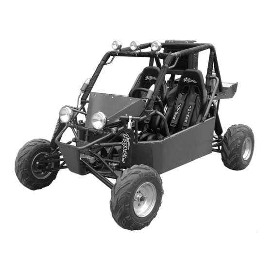
Owner's Manual
JNSZ250DN
Parts Manual
READ THIS MANUAL CAREFULLY
IT CONTAINS IMPORTANT SAFETY INFORMATION.
MINIMUM
16
RECOMMENDED
OPERATOR AGE:
FOR OFF-ROAD USE ONLY
This vehicle is designed and manufactured for off-road use only.
USA only:
It does not confirm to federal motor vehicle safety standards, and operation on
Public streets, roads, or highways is illegal
0
Advertisement
Table of Contents

Subscribe to Our Youtube Channel
Related Manuals for Joyner JNSZ250DN


Summary of Contents for Joyner JNSZ250DN
-
Page 1: Parts Manual
Owner’s Manual JNSZ250DN Parts Manual READ THIS MANUAL CAREFULLY IT CONTAINS IMPORTANT SAFETY INFORMATION. MINIMUM RECOMMENDED OPERATOR AGE: FOR OFF-ROAD USE ONLY This vehicle is designed and manufactured for off-road use only. USA only: It does not confirm to federal motor vehicle safety standards, and operation on... - Page 2 JNSZ250DN Limited Warranty The warranty policy applies to those cases where the new seller vehicle is unloaded from its shipping container, set up and delivered by authorized dealer, and under normal use and service is found to have defects in parts or workmanship under the following terms and conditions.
-
Page 3: Table Of Contents
CONTENTS OWNER’S MANUAL ......................4 FOREWORD........................4 A FEW WORDS ABOUT SAFETY ................. 5 IMPORTANT SAFETY INFORMATION................6 SAFETY LABELS ......................8 ARE YOU READY TO DRIVE?..................10 IS YOUR VEHICLE READY TO DRIVE? ..............12 SAFE DRIVING PRECAUTIONS................. 14 SPECIFICATIONS ....................... - Page 4 28、SEAT AND MUD GUARD ..................71 PREPARATION ATTACH INSTRUCTION ................73 ATTACH BATTERY ...................... 73 ATTACH PROTECTIVE BARS ..................75 ATTACH REAR SHOCK ....................76 ATTACH TRAILING ARM ..................... 77 ATTACH FRONT SHOCK .................... 78 ATTACH FRONT TIRE....................79 ATTACH SEAT AND SAFT BELT ................. 80 ATTACH THE RADIATOR....................
-
Page 5: Owner's Manual
OWNER’S MANUAL FOREWORD Thank you for choosing our Go-Kart. We hope you will have fun with it. Before you start operate the Go-Kart, please read through this Owner’s Manual carefully as it contains important safety and maintenance information. Failure to follow the warnings contained in this manual can result in serious injuries. -
Page 6: A Few Words About Safety
A FEW WORDS ABOUT SAFETY In order to keep everyone safe, you must take responsibility for the safe operation of your Go-Kart. To help you make informed decisions about safety, we have provided operating procedures and other information on labels and in this manual. This information alerts you to potential hazards that could hurt you or others. -
Page 7: Important Safety Information
IMPORTANT SAFETY INFORMATION Your Go-Kart will provide you with many years of service and pleasure. Providing you take responsibility for your own safety and understand the challenges you can meet while driving. There is much that you can do to protect yourself when you drive. You’ll find many helpful recommendations throughout this manual. - Page 8 Never run your Go- Kart indoors. The exhaust from the engine contains a tasteless, odorless and poisonous gas called carbon monoxide. Keep away from moving parts of the Go-Kart The operator of the Go-Kart should never place their hands or other parts of their body near any moving part of the Go-Kart.
-
Page 9: Safety Labels
SAFETY LABELS This section presents some of the most important information and recommendations to help you drive your Go-Kart safely, Please a few moments to read these pages. The labels are considered permanent parts of the Go-Kart. If a label comes off or becomes hard to read, contact your dealer for warning labels replacements. - Page 10 △ WARNING Never shift or engage the reverse lever when the Go-kart is in motion. Only engage the shift lever when the Go-kart is at a full stop. Give a slight throttle and release throttle, then engage shift. Only shift from neutral. The shift lever must be in neutral and parking lever pulled when leaving the Go-kart.
-
Page 11: Are You Ready To Drive
ARE YOU READY TO DRIVE? Before each drive, you need to make sure you and your Go-Kart are both ready to drive. To help get you prepared, this section discusses how to evaluate your driving readiness, what items you should check on your Go-Kart, and adjustments to make for your comfort, convenience, or safety. - Page 12 Driving pants with knee and hip pads, a driving jersey with padded elbows, ■ and a chest/shoulder protector. Drive Training Developing your driving skills is an on-going process. Even if you have derived other Go-Karts, take time to become familiar with how this Go-Kart works and handles.
-
Page 13: Is Your Vehicle Ready To Drive
IS YOUR VEHICLE READY TO DRIVE? Before each drive, it is important to inspect your Go-Kart and make sure any problems are away. A pre-drive inspection is necessary, not only for safety, but also for comfort. because having a breakdown, or even a flat tire, can be a major inconvenience. - Page 14 Throttle ■ Check the free play and adjust if needed. Press the throttle to make sure it moves smoothly without sticking, and snaps back automatically when it is released. Brakes ■ Press the brake pedal several times, check for proper brake pedal free play. Make sure there is no brake fluid leakage.
-
Page 15: Safe Driving Precautions
SAFE DRIVING PRECAUTIONS Off-Road Use Only You Go-Kart and its tires are designed and manufactured for off-road use only, not for pavement. Driving on pavement can affect handling and control. You should not drive your Go-Kart on pavement. Operating this Go-Kart on paved surfaces may seriously affect handling and control of the Go-Kart, and may cause the vehicle to go out of control. - Page 16 a proper speed, you need to consider the capability of your Go-Kart, the terrain, visibility and other operating conditions, plus your own skills and experience. Operating this Go-Kart at excessive speeds increases your changes of losing control of the Go-Kart, which can result in an accident. Always drive at a speed that is proper for your Go-Kart, the terrain, visibility and other operating conditions, and your experience.
-
Page 17: Specifications
SPECIFICATIONS DIMENSIONS Overall Length---------------------------------------------------------------------------------------98 in. (2490mm) Overall Width ---------------------------------------------------------------------------------------- 60 in. (1520mm) Overall Height --------------------------------------------------------------------------------------- 62 in. (1570mm) Wheelbase -------------------------------------------------------------------------------------------- 77.5 in. (1970mm) Front Track ------------------------------------------------------------------------------------------ 51in. (1300mm) Rear Track -------------------------------------------------------------------------------------------50.8in. (1290mm) Ground Clearance ----------------------------------------------------------------------------------- 11.8 in. (300mm) ENGINE Type ------------------------------------------------------------------------------------------ Liquid-cooled. 4-Stroke Bore x Stroke -------------------------------------------------------------------------------------------- 72mm×60mm Displacement ------------------------------------------------------------------------------------------------------ 244 cc Corrected compression ratio ------------------------------------------------------------------------------------ 10:1... -
Page 18: Operation
OPERATION Operation controls WARNING-Do not attempts to start or operate the engine until completely familiar with the location and use of each control necessary to operate this vehicle. The operator must know how to stop this machine before starting and driving it. - Page 19 d. Run you kart Press the shift lever forwards to “L” position, the cart will move forwards at low speed, “H” position, high speed; “N” position, no speed; and “R” position the cart will move backwards. (Note: if the shift can’t engage, give a slight throttle, then try it again) If the shift engages press down the throttle pedal slowly, the cart will accelerate.
- Page 20 necessary. Check Throttle. Check for smooth operation. Assure throttle “snaps” back to idle. g. Check Engine Stop Button. Perform engine stop button test. Repair as necessary. h. Check all Nuts, Bolts, and fasteners. Check wheels to see that all axle nuts and lug nuts are tightened properly.
- Page 21 m. Component locations STEERING WHEEL SAFETY BELT RADIATOR FUEL TANK WATER TANK BATTERY MUFFLER...
- Page 22 Passengers The vehicle allows for two riders Seat adjustment handle only. Combine maximum weight of driver and the passenger should not exceed 180kg (400Ibs). Seat Adjustment The seat must always be securely fastened in the position which best affords the operator control of the foot pedals, steering wheel, and the remote stop button.
- Page 23 Never engage the shift lever when the Go-kart is in motion Only engage the shift lever when the Go-kart is at a full stop Give a slight throttle and loosen throttle, then engage shift from neutral to shift. The shift lever must be on neutral and pull parking lever when leave the Go-kart Parking Adjustment Press down the reverse lever to the “F”...
-
Page 24: Service Instruction
SERVICE INSTRUCTION A. Air cleaner clean. Filter core Every 80 hours, service air Cover 1 cleaner one time under dusty conditions. Service more often. a. Remove cleaner cover 1. b. Remove air cleaner filter core (See Fig. 9) Check the filter paper, if the filter paper is dusty, please clean with pressure gas or replace with a new one... - Page 25 a. Remove the spark plug and inspect it (Use a spark plug wrench) The electrodes should be kept clean and free of carbon. The presence of carbon or excess oil will greatly reduce proper engine performance. If possible, check the spark plug gap (area between electrodes) using a wire feeler gauge.
- Page 26 the chain will become loose and tight. Repeat this procedure until chain is at proper tension. c. Tighten all of the nuts. NUT #2 NUT #1 BOLT #1 Figure 13 J. Adjustment of Front and Rear Shock There are five adjustable positions on each Front shock. The default position is in the first set by manufacture (See Fig.14) Use a round nut wrench as you adjust the front shock, the tension of shock spring will increase as you screw to left, decrease as you screw to the right.
- Page 27 engine slowly to spread oil and replace spark plug. c. Do not save or store gasoline over winter. Using old gasoline, which has deteriorated from storage, will cause hard starting and affect engine performance. Do not drain fuel while engine is hot. Be sure to move Go-Kart outside before draining fuel.
-
Page 28: Repair
REPAIR A. Front Wheel Replacement Do not disassemble the castle nuts when you replace the front wheels. It is only necessary to tighten the nuts so that the wheel turns freely on the axle with minimum endplay. (See Fig. 16) Tighten the nuts after replacing the wheels. -
Page 29: Periodical Check And Services
PERIODICAL CHECK AND SERVICES The maintenance intervals in the following table are based upon average driving conditions. Driving in unusually dusty areas, require more frequent servicing. Time of Initial service Monthly Quarterly Yearly service Items (First week) Tire pressure/wear Brake performance Tightness of screws Air cleaner Carburetor... -
Page 30: Wiring Diagram
WIRING DIAGRAM... -
Page 31: Parts Manual
PARTS MANUAL 1、CRANKCASE ASSY. ENGLISH Q’ty 172MM-C-011100 CRANK CASE ASSY.L 172MM-C-011200 CRANK CASE ASSY.R 172MM-011001 SEAL 28X40X8 172MM-011002 SEAL RING.INNER OIL PIPE. 172MM-011004 STUD A.CYLINGDER 152MI-021005 LOCATING PIN Φ10x14 172MM-011005 STUD B.CYLINGDER 172MM-B-011006 SEAL WASHER.CRANK CASE 172MM-011400 INNER OIL PIPE ASSY 152MI-021019 BOLT M6X12 152MI-011017... - Page 32 1、CRANKCASE ASSY. ENGLISH Q’ty GB/T 9877-1988 FB33X35X5 OIL SEAL FB 33X35X5 GB/T 276-1994 6201 BEARING 6201 GB/T 276-1994 620-RS BEARING 6202-RS 172MM-B-068001 HOLLOW BOLT M14X1.5 CF188-068002 WASHER 14.4X22X1 CF188-068003 SPACER SPRING GB/T308-1989 3/8 STEEL BALL 152MI-130004 "O" RING FOR SEAL13.5X1.4 172MM-B-011300 ODOMETER SENSOR 172MM-B-011400...
-
Page 33: Side Cover Assy.l
2、SIDE COVER ASSY.L ENGLISH Q’ty 172MM-B-012001 SIDE COVER.L 172MM-B-012002 AIR DAMPER GB/T818-2000 M6X12 SCREW 172MM-B-012005 BOLT 152MI-013008 BOLT 152MI-021005 LOCATING PIN Φ10x14 172MM-B-012003 SEAL WASHER.LEFT SIDE COVER 152MI-021018 BOLT... -
Page 34: Right Cover Assy
3、RIGHT COVER ASSY ENGLISH Q’ty 172MM-013013 AIR PIPE.CYLINDER HEAD COVER 172MM-013100 BREATH PIPE.RIGHT SIDE COVER 172MM-013015 BREATH PIPE.AIR FILTER 172MM-013016 CLAMP.BREATH PIPE 172MM-013002 SIDE COVER.R 172MM-013008 PRESS PLATE.CABLE 172MM-013012 SEAL WASHER.RIGHT SIDE COVER 172MM-013007 CAP.OIL FILTER 152MI-013100 OIL FILTER CORE 172MM-013006 SPRING 172MM-013001... - Page 35 3、RIGHT COVER ASSY ENGLISH Q’ty QC/T621-1999-A12 CLAMP 10 172MM-013010 BREATH FAUCET 172MM-013009 WATER OUTLET FAUCET 152MI-013009 BOLT M6X40 172MM-013026 PROTECTION PIPE 152MI-071007 BOLT M6X28 1P52MI-011018 BOLT M6X70...
-
Page 36: Cylingder Head Caseing Assy
4、CYLINGDER HEAD CASEING ASSY ENGLISH Q’ty 172MM-021009 CLAMP.OIL PIPE 172MM-021001 COVER.CYLINDER HEAD 172MM-021006 STOP PLATE 152MI-021011 SEAL WASHER. 172MM-021100 AXIS.SWING ARM.INLET 172MM-021200 AXIS.SWING ARM.OUTLET 172MM-021400 OIL PIPE ENGINE.OUTER 152MI-021001 RUBBER RING.OIL PIPE 172MM-021431 MOUNT.OIL PIPE 152MI-021003 SHOCK ABSORBER RUBBER STRIP 152MI-021004 REAMED BOLT A M8X25 152MI-021015... - Page 37 4、CYLINGDER HEAD CASEING ASSY ENGLISH Q’ty 152MI-021018 BOLT M6X55 172MM-021404 SHOCK ABSORBER SLEEVE 172MM-021002 BREATH PIPE FAUCET 172MM-021300 MOUNT.AIR FILTER 172MM-021008 BLOCKING...
-
Page 38: Cylingder Head Assy
5、CYLINGDER HEAD ASSY ENGLISH Q’ty 172MM-022100 CYLINDER HEAD 172MM-022700 FLANGE.EXHAUST 152MI-022014 BEARING COVE.CAM AXIS 172MM-022008 NUT.EXHAUST 172MM-022010 SEAL WASNER.CYLINDER HEAD 172MM-022900 CARBURETOR SEAT UNIT 172MM-022500 CLAMP UNIT.AIR INLET PIPE 152MI-022810 THERMOSTAT 152MI-022803 THERMOSTAT SHELL.UPPER 152MI-022021 RUBBER PIPE1.CARBURETOR 172MM-022601 THERMOSTAT SHELL.LOWER 172MM-022400 SPARK PLUG 152MI-022017... - Page 39 5、CYLINGDER HEAD ASSY ENGLISH Q’ty QC/T621-1999-A6.5 STEEL RING CLAMP 152MI-090005 BOLT M6X16 152MI-023008 BOLT M6X18 152MI-022017 BREATHE PIPE.CARBURETOR GB/T848-85-6-D·Cr SMALL WASHER 152MI-022021 SCREW BLOCKAGE...
-
Page 40: Cylinger Body Assy
6、CYLINGER BODY ASSY ENGLISH Q’ty 172MM-023100 CYLINDER 172MM-023002 SEAL WASHER.CYLINDER 152MI-023300 TENSIONER UNIT 152MI-023307 BOLT.SPRING SEAT 152MI-023306 SPRING.TENSIONER 152MI-023004 SEAL WASHER.TENSIONER 172MM-023007 RUBBER PIPE.WATER INLET 172MM-023009 JACKET.WATER PIPE QC/T621-1999-B24 STEEL BAND CLAMP 152MI-023305 WASHER 8.5 GB/T848-85-6-D·ZN SMALL WASHER 152MI-021005 LOCATION PIN Φ10X14 152MI-023008 BOLT M6X18 152MI-080013... -
Page 41: Timing Chain
7、TIMING CHAIN ENGLISH Q’ty 172MM-022200 CHAIN UNIT 172MM-023200 TENSION PLATE 172MM-023001 CHAIN GUIDE PLATE GB96-85-6-D·Zn BIG WASHER GB/T5781-2000-M6X12-D·Zn BOLT... -
Page 42: Magnetor Assy
8、MAGNETOR ASSY ENGLISH Q’ty 172MM-094000 FREE-WHEELING CLUTCH 172MM-033000 TRIGGER COIL 172MM-013008 CABLE PRESS BAND 172MM-031000 FREE-WHEELING 172MM-032000 STATOR UNIT GB/T70.1-2000-M8X18 SOCKET HEAD SCREW 172MM-040001 NUT M16X1 172MM-040002 WASHER16.3X30X2 152MI-030002 BOLT M5X16 152MI-060002 BOLT M6X30... -
Page 43: Admission Machanism
9、ADMISSION MACHANISM ENGLISH Q’ty 152MI-022500 SEAL.VALVE ROD 172MM-022300 CAM UNIT 152MI-021007 SWING ARM 172MM-022001 INTAKE VALVE 172MM-022005 EXHAUST VALVE 172MM-022002 VALVE SPRINGL.OUTTER 172MM-022003 VALVE SPRINGL.INNER 152MI-022005 PAN.VALVE SPRING 152MI-022001 SEAT.VALVE SPRING 152MI-022006 CLAMP.VALVE NTN: 16002 BALL BEARING GB894.A-1-86-15 AXIS RETAINER RING 172MM-022310 CHAIN PULLY 172MM-022301... -
Page 44: Crank Link Lever & Piston
10、CRANK LINK LEVER & PISTON ENGLISH Q’ty 172MM-A-041000 CRANK LINK UNIT 172MM-040008 PISTON RING 172MM-040009 PISTON RING 172MM-042000 OIL RING 172MM-040005 PISTON 172MM-040007 PISTON PIN 152MI-040011 JOINT.OIL CHANNEL 152MI-040010 JOINT SPRING 152MI-040006 WOODRUFF KEY 172MM-040006 STOP RING.PISTON PIN GB/T119-2000-2X14... -
Page 45: Speed Changer
11、SPEED CHANGER. ENGLISH Q’ty 172MM-021007 NUT M14X1.5 172MM-021006 WASHER14.5X30.2 172MM-A-051005 DRIVE WHEEL PAN 172MM-A-051003 SLEEVE.DRIVE WHEEL PAN 172MM-A-051100 MOVABLE DRIVE PAN 172MM-A-051200 OFFCENTER ROLLER 172MM-A-051004 SLIDING BLOCK 172MM-A-051002 PUSH PAN... -
Page 46: Clutch Assy
12、CLUTCH ASSY ENGLISH Q’ty 172MM-052008 BOLT M12X1.25 172MM-A-052500 OUTTER WHEEL DISC 172MM-052005 THIN NUT M30X1 172MM-A-052400 DRIVE PAN UNIT 172MM-A-052200 DAMPING RUBBER BLOCK 172MM-A-052600 CLUTCH BLOCK 172MM-A-052006 RELEASE SPRING 172MM-A-052003 SIDE PAN GB/T896-1986-9 SPLIT WASHER 172MM-052310 NEEDLE BEARING GB/T893.1-1986-28 RETAINER RING.HOLE GB/T278-1989-1060902 BEARING 172MM-A-052300... -
Page 47: Gearbox Cover Assy
13、GEARBOX COVER ASSY ENGLISH Q’ty 172MM-C-060001 COVER.GEARBOX 172MM-C-060002 PAPER WASHER.GEARBOX 172MM-013005 BOLT M12X1.5.OIL OUTLET 152MI-021014 WASHER12 172MM-B-069000 SHIFT DISPLAY SWITCH GB/T 276-1994 6202-RS BALL BEARING GB/T 276-1994 6201 BALL BEARING GB/T 276-1994 6203 BALL BEARING GB/T 276-1994 6305-RS BALL BEARING 172MM-B-011107 BOLT M8X48 172MM-B-011111... -
Page 48: Transmission Gear Assy
14、TRANSMISSION GEAR ASSY ENGLISH Q’ty 172MM-B-067000 TRANSITION GEARS ASSY GB/T89431-1986 20 RTAINER RING 172MM-B-067000 TRANSITION GEAR 172MM-B-067001 TRANSITON GEAR-AXIS 172MM-B-060001 MAIN AXIS 172MM-B-062000 SECONDARY AXIS ASSY 172MM-B-062006 WASHER.15X28X2 172MM-B-062002 DRIVEN GEAR.HIGH SPEED NTN: K16X20X10 NEEDLE BEARING 172MM-B-062009 SLIDING SLEEVE.SHIFT 172MM-B-062001 SECONDARY AXIS 172MM-B-062007 WASHER 24X33X2... -
Page 49: Transmission Gear Assy
14、TRANSMISSION GEAR ASSY ENGLISH Q’ty CF188-061007 RETAINER RING.AXIS 25 172MM-C-063001 OUTPUT AXIS 172MM-C-063004 CHAIN PULLEY 172MM-C-063005 PRESS PLATE.CHAIN PULLEY 172MM-C-063009 BOTL M6X12 172MM-B-062008 WASHER 16X28X2... -
Page 50: Gear Shift Machanism
15、GEAR SHIFT MACHANISM ENGLISH Q’ty 172MM-B-066000 SHIFT DRUM ASSY 172MM-B-066002 SHIFT YOKE 172MM-B-066003 PIN.SHIFT YOKE 172MM-B-066004 SNAP RING.PIN.SHIFT YOKE 172MM-B-066001 SHIFT DRUM 172MM-B-066005 TOUCH CHIP.SPEED DISPLAY CF188-065201 WASHER.DRIVEN SECTOR GEAR CF188-065203 DRIVEN SECTOR FEAR.SHIFT CF188-065204 WASHER 13.5X22X1 CF188-065202 DRIVEN SECTOR GEAR-AXIS.SHIFT CF188-065204 SPRING.DRIVEN SECTOR GEAR CF188-065206... -
Page 51: Engine Oil Pump Assy
16、ENGINE OIL PUMP ASSY ENGLISH Q’ty 151MI-071000 OIL PUMP ASSY 151MI-071002 OIL PUMP BODY 151MI-071003 OIL PUMP COVER 151MI-071001 OIL PUMP AXIS 151MI-071001 CHAIN PULLEY.OIL PUMP 151MI-073000 CHAIN OIL PUMP 151MI-071004 ROTOR.OIL PUMP.INNER 151MI-071005 ROTOR.OIL PUMP.OUTTER 151MI-070002 SPACER PLATE A.OIL PUMP 151MI-072000 SPACER PLATE B.OIL PUMP GB878-85-M3X12... -
Page 52: Coolant Pump Assy
17、COOLANT PUMP ASSY ENGLISH Q’ty 172MM-080004 IMPELLER.WATER PUMP 152MI-081000 WATER SEAL ASSY 172MM-080003 WATER PUMP COVER 172MM-080002 SEAL WASHER. COVER 172MM-080001 WATER PUMP AXIS 152MI-013009 BOLT M6X40 152MI-021017 BOLT M6X25 GB/T893.1-1986-19 RETAINER RING.HOLE 152MI-080007 WASHER.7.5X13X1.2 152MI-080011 WASHER.6X12X1 NTN: 6800 NEEDLE BEARING 172MM-080005 GREASE SEAL 10X20X5 152MI-080008... -
Page 53: Electric Starter Assy
18、ELECTRIC STARTER ASSY ENGLISH Q’ty 172MM-090001 AXIS.DUPLICATE GEAR 172MM-092000 DRIVEN GEAR COMP 172MM-091000 DUPLICATE GEAR COMP 172MM-090007 MOUNTING PLATE 172MM-093000 STARTER COMP 152MI-080013 BOLT M6X22 172MM-090008 BOLT M6X14... -
Page 54: Carburetor Assy
19、CARBURETOR ASSY ENGLISH Q’ty 172MM-100000 CARBURETOR ASSY... -
Page 55: Frame&Fuel Tank&Rediator
20、FRAME & FUEL TANK&REDIATOR 20 FRAME&FUEL TANK&REDIATOR 13 14... - Page 56 20 FRAME&FUEL TANK&REDIATOR PART NO. DESCRIPTION Q'TY DN250.01.01.00.00 MAIN FRAM DN250.01.02.00.06 COVER.FR DN250.01.02.00.04 SPORT WING.L DN250.01.02.00.03 SPORT WING.LOWER DN250.01.02.00.05 SPORT WING.R DN250.01.02.00.02 SPORT WING.UPPER GB5787-86 M12X1.25X55 FLANGE BOLT M12X1.25X55 D250.11.771 NYLON BUSHING GB6177.1-2000 M12 FLANGE NUT M12 DN250.01.02.08.00 PROTECTIVE BAR.R GB5787-86 M10X1.25X20 FLANGE BOLT M10X1.25X20 GB6177.1-2000 M10...
-
Page 57: Front Suspension
21、FRONT SUSPENSION 21 FRONT SUSPENSION 41 42... - Page 58 21 FRONT SUSPENSION PART NO. DESCRIPTION Q'TY DN250.02.03.00.00 LOWER A-ARM.R DN250.02.06.00.00 KNUCKLE.R DN250.04.01.00.01 BRAKE CLIPPER 1 DN250.02.01.00.00 UPPER A-ARM.R GB5787-86 M14X1.5X90 FLANGE BOLT M14X1.5X90 DN250.02.04.00.00 UPPER A-ARM.L GE20C JOINT BEARING GE20C GB893.1-86 35 RETAINOR RING.HOLE 35 DN250.02.00.00.05 SPACER.GE20C GB6177.1-2000 M14x1.5 FLANGE NUT M14x1.5 GB5787-86 M14X1.5X60 FLANGE BOLT M14X1.5X60...
-
Page 59: Steering&Throttle&Brake&Shift
22、 STEERING&THROTTLE&BRAKE&SHIFT 22 STEERING&THROTTLE&BRAKE&SHIFT... - Page 60 22 STEERING&THROTTLE&BRAKE&SHIFT Q'TY PART NO. DESCRIPTION POSA12L ROD END BEARING POSA12L GB6172-86 M12L THIN NUT M12L DN250.03.02.00.00 TIE ROD GB5785-86 M12×80 BOLT M12X80 D800.05.01.00.04 REINFORCED SHEET.TIE ROD D800.05.01.00.03 SPACER.TIE ROD D800.05.01.03.07 DUST GUARD PLATE D800.05.01.03.06 SUPPORT.TIE ROD D800.05.01.03.08 GREASE CUP M8X1 D800.05.01.03.01 CASE.STEERING BOX D800.05.01.03.04...
- Page 61 22 STEERING&THROTTLE&BRAKE&SHIFT Q'TY PART NO. DESCRIPTION D250.04.002 BUFFER BUSHING.LINK ROD GB5787-86 M6x30 FLANGE BOLT M6x30 DN250.04.02.00.00 FOOT BRAKE BOARD DN250.05.02.00.01 PIN.FOOT BOARD.THROTTLE DN250.05.02.00.01 FOOT BOARD.THROTTLE DN250.05.02.02.00 CABLE.THROTTLE JD10.82.101 RUBBER BUSHING.SHIFT DI250.05.03.03.00 SHIFT LEVER D250.08.004 SPRING.SHIFT D250.08.005 STOP RING D250.08.009 COVER.SHIFT LEVER GB/T95-1985 8 PLAIN WASHER 8 GB91-86 3x30...
-
Page 62: Engine Rack&Transmission
23、ENGINE RACK&TRANSMISSION 23 ENGINE RACK&TRANSMISSION... - Page 63 23 ENGINE RACK&TRANSMISSION PART NO. DESCRIPTION Q'TY DN250.07.01.00.00 CV AXLE.ASSY DI250.07.01.00.01 BRIDLE.BOOT DI250.07.01.00.04 OUTER BOOT DI250.07.01.00.03 BRIDLE.BOOT DI250.07.01.00.02 INNER BOOT DI250.07.00.00.01 STEEL THREAD CIRCLIP GB894.1-86 26 CIRCLIP FOR AXIS 26 GB77-85 M5×6 HOLDING SCREW M5x6 DN250.07.00.00.03 SLEEVE.SPROCKET SHAFT GB9877.1 — 88 FB 38X62X8 GEASE SEAL FB 38x62x8 GB893.1-86 62 CIRCLIP FOT HOLE 62...
-
Page 64: Engine Assembly
24、ENGINE ASSEMBLY 24 ENGINE ASSEMBLY CONNECT TO CCA 31 32... - Page 65 24 ENGINE ASSEMBLY PART NO. DESCRIPTION Q'TY DI250.05.01.01.01 RADIATOR DI250.05.01.01.02 VALVE.REDIATOR DN250.05.01.00.04 SUCTION PIPE GB5787-86 M8x20 FLANGE BOLT M8X20 D800.04.02.02.00 WATER TANK.GK800 D800.04.02.02.02 SEAL CUSHION D800.04.02.02.01 CAP.WATER TANK GB6187.1-2000 M8 FLANGE LOCK NUT M8 DN250.05.01.00.05 OVERFLOWING PIPE DN250.05.01.00.01 WATER PIPE.OUTLET.ENGINE DN250.05.01.00.02 WATER PIPE.INLET.ENGINE GB5787-86 M6x20...
-
Page 66: Exhaust&Shift
25、EXHAUST&SHIFT 25 EXHAUST&SHIFT&PARKING BRAKE... - Page 67 25 EXHAUST&SHIFT Q'TY PART NO. DESCRIPTION DI250.07.04.00.00 ENGINE ASSEMBLY DI250.05.03.05.00 GEAR SHIFT ARM DI250.05.03.00.05A FIXED MOUNT OF SHIFT CABLE 3.1 DI250.05.03.00.03A FIXED MOUNT OF SHIFT CABLE 1.1 GB/T5787-1986 M6x10 HEXAGON-HEADED FLANGE BOLT M6X10 DN250.05.03.04.00 SHIFT CABLE GB/T95-1985 8 PLAIN WASHER 8 GB/T91 2x25 COTTER PIN 2X25 GB/T5787-1986 M8x20...
-
Page 68: Rear Suspension
26、REAR SUSPENSION 26 REAR SUSPENSION... - Page 69 26 REAR SUSPENSIONG PART NO. DESCRIPTION Q'TY DN250.04.01.00.02 BRAKE CALIPER 2 DN250.09.02.00.00 TRAILING ARM.R GB/T93-1987 8 SPRING WASHER 8 GB/T95-1985 8 PLAIN WASHER 8 GB5787-86 M8X15 FLANGE BOLT M8X15 GB6177.1-2000 M10X1.25 FLANGE NUT M10X1.25 D650.02.01.00.02 STEEL BUSHING.TRAILING ARM D650.02.01.00.01 RUBBER BUSHING.TRAILING ARM GB5787-86 M10X1.25X70 FLANGE BOLT M10X1.25X70 DN250.09.01.00.00...
-
Page 70: Electrical Assembly
27、ELECTRICAL ASSEMBLY 27 ELECTRICAL ASSEMBLY... -
Page 71: Electrical Assembly
27、ELECTRICAL ASSEMBLY 27 ELECTRICAL ASSEMBLY PART NO. DESCRIPTION Q'TY D650.00.12.00 SPOT LIGHT D250.07.901 TURNING SINGLE.FR DI250.10.04.00.00 FLASH APPARATUS D250.07.915 VOLTAGE REGULATOR DI250.10.05.00.00 IGNITION COIL D250.07.917 D250.07.912 STARTER RELAY FLASH APPARATUS DN250.10.01.02.00 DI250.10.04.00.00 FUSE BOX D250.07.913 HORN D250.07.802 BATTERY D800.06.00.00.12 TAIL LIGHT ASSEMBLY DN250.10.01.01.00 BALE OF WIRE D250..07.909... -
Page 72: Seat And Mud Guard
28、SEAT AND MUD GUARD 28 SEAT AND MUD GUARD... -
Page 73: Seat And Mud Guard
28 SEAT AND MUD GUARD Q'TY PART NO. DESCRIPTION DS250.08.01.00.03 SEAT COMP.R DS250.08.01.00.02 SEAT COMP.L GB6177.1-2000 M10X1.25 FLANGE NUT M10X1.25 D250.11.005A SAFTY BELT DI250.11.01.00.07 SEAT ADJUSTER.R DI250.11.01.00.06 SEAT ADJUSTER.L 444.6.20 SCREW.PHILIPS HEAD M6X20 D250.11.058 RUBBER WASHER 6 GB6177.1-2000 M6 FLANGE NUT.LOCK M6 D250.11.005A MUD GUARD DN250.11.01.00.05... -
Page 74: Preparation Attach Instruction
PREPARATION ATTACH INSTRUCTION ATTACH BATTERY STEP 1:FILL THE ELECTROLYTE AS BELOW a) Pull the seal cap out of the plastic bottle b) Turn over the seal cap 180 degree, fix it on the outlet of plastic bottle a) Cut the inlet of plastic bottle b) Fill the battery with electrolyte to upper lever by inserting every inlet of the battery STEP 2:Put the battery into the box on go-kart. - Page 75 Notice: Before use new battery, it needs to notice follows: 1- After the battery is filled electrolyte, the new battery need to recharge as the Owner’s manual said. Otherwise, the new battery will be damaged and can’t recharge. 2- The new battery can’t overload in use, otherwise it damage forever. The new battery need to maintenance with recharge as the Owner’s manual said.
-
Page 76: Attach Protective Bars
ATTACH PROTECTIVE BARS 1、 2、 3、 4、... -
Page 77: Attach Rear Shock
ATTACH REAR SHOCK a) Remove the bolt and the nut b) Attach the rear shock as below picture: SPACER SPACER... -
Page 78: Attach Trailing Arm
ATTACH TRAILING ARM 1、 2、... -
Page 79: Attach Front Shock
ATTACH FRONT SHOCK... -
Page 80: Attach Front Tire
ATTACH FRONT TIRE The hub to fix the front tire is packed as below: 1- Remove four nuts, four spring washers, and four plain washers on the hub. 2- Fix the rim on the hub. 3- Insert the washers, spring washers through bolt on the hub. Tighten four nuts. Notice: Direction marked on the tire must correspond to the vehicle forward... -
Page 81: Attach Seat And Saft Belt
ATTACH SEAT AND SAFT BELT FIX SAFTY BELT... -
Page 82: Attach The Radiator
ATTACH THE RADIATOR 1- Attach the radiator as below pictures. 2- Connect wire from fan motor to main wire. 3- Arrange the main and reserve coolant rubber tube as below picture. -
Page 83: Attach Silencer
ATTACH SILENCER...
Need help?
Do you have a question about the JNSZ250DN and is the answer not in the manual?
Questions and answers