Table of Contents
Advertisement
Quick Links
Owner's Manual
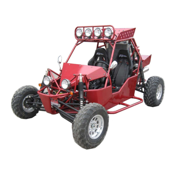
JNSZ800MV
READ THIS MANUAL CAREFULLY
IT CONTAINS IMPORTANT SAFETY INFORMATION.
16
MINIMUM
RECOMMENDED
OPERATOR AGE:
FOR OFF-ROAD USE ONLY
This vehicle is designed and manufactured for off-road use only.
USA only:
It does not confirm to federal motor vehicle safety standards, and operation on
Public streets, roads, or highways is illegal
1
Advertisement
Table of Contents

Related Manuals for Joyner JNSZ800MV


Summary of Contents for Joyner JNSZ800MV
- Page 1 Owner’s Manual JNSZ800MV READ THIS MANUAL CAREFULLY IT CONTAINS IMPORTANT SAFETY INFORMATION. MINIMUM RECOMMENDED OPERATOR AGE: FOR OFF-ROAD USE ONLY This vehicle is designed and manufactured for off-road use only. USA only: It does not confirm to federal motor vehicle safety standards, and operation on...
- Page 2 Should warranty service be required on your JNSZ800MV during the 90 days warranty period, please contact the nearest authorized dealer for repairs. What is not covered under this warranty? This warranty does not cover any seller vehicle that has been subjected to: a.
-
Page 3: Table Of Contents
CONTENTS OWNER’S MANUAL ......................4 1.FOREWORD ......................4 2.A FEW WORDS ABOUT SAFETY ................5 3.IMPORTANT SAFETY INFORMATION ..............6 4.SAFETY LABELS ....................... 8 5.ARE YOU READY TO DRIVE? .................. 9 6.IS YOUR VEHICLE READY TO DRIVE? ..............11 ... -
Page 4: Owner's Manual
OWNER’S MANUAL 1.FOREWORD Thank you for choosing our Go-Kart. We hope you will have fun with it. Before you drive the Go-Kart, please read through this Owner’s Manual carefully as it contains important safety and maintenance information. Failure to follow the warnings contained in this manual can result in serious injuries. Be sure to follow the recommended maintenance schedule and service your kart accordingly. -
Page 5: A Few Words About Safety
2.A FEW WORDS ABOUT SAFETY In order to keep everyone safe, you must take responsibility for the safe operation of your Go-Kart. To help you make informed decisions about safety, we have provided operating procedures and other information on labels and in this manual. This information alerts you to potential hazards that could hurt you or others. -
Page 6: Important Safety Information
3.IMPORTANT SAFETY INFORMATION Your Go-Kart will provide you with many years of service and pleasure. Providing you take responsibility for your own safety and understand the challenges you can meet while driving. There is much that you can do to protect yourself when you drive. You’ll find many helpful recommendations throughout this manual. - Page 7 harm to your body. Skidding or Sliding The terrain surface can be a major factor affecting turns, Skidding a turn is more likely to occur on slippery surfaces such as snow, ice, mud and loose gravel. If you skid on ice, you may lose all directional control.
-
Page 8: Safety Labels
4.SAFETY LABELS This section presents some of the most important information and recommendations to help you drive your Go-Kart safely. Spend a few moments to read these pages. The labels are considered permanent parts of the Go-Kart. If a label comes off or becomes hard to read, contact your dealer for warning labels replacements. -
Page 9: Are You Ready To Drive
5.ARE YOU READY TO DRIVE? Before each drive, you need to make sure you and your Go-Kart are both ready to drive. To help get you prepared, this section discusses how to evaluate your driving readiness, what items you should check on your Go-Kart, and adjustments to make for your comfort, convenience, or safety. - Page 10 Drive Training Developing your driving skills is an on-going process. Even if you have derived other Go-Karts, take time to become familiar with how this Go-Kart works and handles. To build skills, Practice driving the Go-Kart in a safe area, do not drive in rough terrain until you get accustomed to the Go-Kart’s controls, and feel comfortable with its size and weight.
-
Page 11: Is Your Vehicle Ready To Drive
6.IS YOUR VEHICLE READY TO DRIVE? Before each drive, it is important to inspect your Go-Kart and make sure any problems are away. A pre-drive inspection is necessary, not only for safety, but also for comfort. Because any a breakdown, or even a flat tire, can be a major inconvenience. If your Go-Kart has overturned or has been involved in a collision, do not drive it until your dealer has inspected your Go-Kart, There may be damages or other problems you cannot see. - Page 12 Throttle ■ Check the free play and adjust if needed. Press the throttle to make sure it moves smoothly without sticking, and snaps back automatically when it is released. Brakes ■ Press the brake pedal several times, check for proper brake pedal free play. Make sure there is no brake fluid leakage.
-
Page 13: Safe Driving Precautions
7.SAFE DRIVING PRECAUTIONS Off-Road Use Only You Go-Kart and its tires are designed and manufactured for off-road use only, not for pavement. Driving on pavement can affect handling and control. You should not drive your Go-Kart on pavement. Operating this Go-Kart on paved surfaces may seriously affect handling and control of the Go-Kart, and may cause the vehicle to go out of control. - Page 14 speed, you need to consider the capability of your Go-Kart, the terrain, visibility and other operating conditions, plus your own skills and experience. Operating this Go-Kart at excessive speeds increases your changes of losing control of the Go-Kart, which can result in an accident. Always drive at a speed that is proper for your Go-Kart, the terrain, visibility and other operating conditions, and your experience.
-
Page 15: Specifications
8.SPECIFICATIONS DIMENSIONS Overall Length------------------------------------------------------------------------------------------------------------------113 in. (2880mm) Overall Width ---------------------------------------------------------------------------------------------------------------------68in. (1740mm) Overall Height -------------------------------------------------------------------------------------------------------------------- 67in. (1700mm) Wheelbase ----------------------------------------------------------------------------------------------------------------------- 82 in. (2090mm) Front Track ----------------------------------------------------------------------------------------------------------------------- 58 in. (1475mm) Rear Track --------------------------------------------------------------------------------------------------------------------------58in.(1470mm) Ground Clearance ----------------------------------------------------------------------------------------------------------- 12 1/2in. (320mm) ENGINE Type ------------------------------------------------------------------------------------------------------------ 3-Bore, 4-Stroke, Liquid-cooled Bore x Stroke -------------------------------------------------------------------------------------------------------------------- 72mm×66.5mm Displacement -------------------------------------------------------------------------------------------------------------------------------- Corrected compression ratio --------------------------------------------------------------------------------------------------------------- 9.5:1... -
Page 16: Operation Instruction
9.OPERATION INSTRUCTION WARNING-Do not attempts to start or operate the engine until completely familiar with the location and use of each control necessary to operate this vehicle. Operator must know how to stop this machine before starting and driving it. Control pedal 1) Accelerator Pedal: Changes engine rpm and vehicle ground speed. - Page 17 start engine in neutral. (See figure 3) • Pull up on shift selector collar and move lever to position “1” “2” “3” “4”, the vehicle will move forwards at different speed. • Pull up on shift selector collar and move lever to center position to place trans-axle in neutral.
- Page 18 Oil pressure gauge: Indicates oil pressure. If the needle point to red area, stop engine immediately. Check oil level and add if low. See authorized Joyner dealer if needle stays on and engine is full of oil. (See figure 8) 18) Reverse gear light: indicate reverse gear engaged if illuminated.
- Page 19 transported in factory-supplied seating. Operator and passenger are responsible for deciding if their situation warrants using Seat Belts. Seat The seats must always be securely fastened Seat adjustment handle in the position which best affords the operator control of the foot pedals, steering wheel, and the remote stop button.
-
Page 20: Maintenance
Chassis Maintenance 1. Tire Maintenance Use only tires recommended by Joyner. It is important for your safety and the safety of others that the tires have correct air pressure. Check air pressure in four tires before each use. Visually inspect tires for loss of air throughout each day of operation. See Tire inflation Chart below for correct tire pressure. - Page 21 After a long time of use, it is necessary to adjust the spring as following: (See figure 15) 5.1. Loosen the lock nut with a shock absorber wrench (by Joyner); 5.2. Screw the stop-nut clockwise, and the tension of shock spring will increase; decrease as screw to left.
- Page 22 6. Front Wheel Replacement Do not disassemble the center castle nuts when you replace the front wheels. (See Fig. 16) Tighten the nuts after replacing the wheels. FIGURE 16 7. Rear Wheel Replacement Do not disassemble the center castle nuts when you replace the front wheels. (See Fig.
- Page 23 8. Clutch replacement Remove two bolts, and demount Starter-assembly carefully. (See Fig. 18-21) Q1840845 Q1841245 FIGURE 18 FIGURE 19 S11-3708111 S11-3708110GA FIGURE 21 FIGURE 20 2. Remove four bolts on the transmission case, lay down these carefully. Caution: When fix the four bolts in the transmission case;...
- Page 24 FIGURE 24 FIGURE 25 3. Remove upper steel cushions and lower steel cushion. (See Fig. 26-27) 372-100203 S11-170010 FIGURE 26 FIGURE 27 4.Insert a spine-shaft into the hole of the Clutch assy , remove the six bolts on the Clutch pressure plate, now It’s clear.
- Page 25 S11-1601020 S11-1601030 FIGURE 31 FIGURE 30 FIGURE 32 5. Insert a spline-shaft into the hole of the Clutch assy , fix the six bolts on the Clutch pressure plate , tighten them according to the prescribed torque 28 N.M . (See Fig. 33-34) FIGURE 33 FIGURE 34 6.
- Page 26 9. Front Wheel Alignment 9.1. Put the vehicle on level ground. 9.2. The “toe-in” of the front wheels should be 0.63 inches. To check alignment, measure distance A and B between the centerline (CL) of the wheels. The proper toe-in dimension A should be 0.63 inches greater than dimension B.
- Page 27 13. PERIODICAL CHECK AND SERVICES The maintenance intervals in the following table are based upon average driving conditions. Driving in unusually dusty areas, require more frequent servicing. Time of service Initial Monthly Quarterly Yearly Item service Engine 1. Tighten bolts on engine. 2.
- Page 28 14. ENGINE WIRING DIAGRAM...
- Page 29 15. MAIN WIRING DIAGRAM...
- Page 30 Engine maintenance 1. Service Air Filter Service air filter every 80 hours NOTE: Service more often under dusty conditions. Filter Cover Rubber bushing FIGURE 36 Remove filter cover (See Fig. 36) Check the filter cover and the air filter, if the filter cover and the air filter are dusty, please clear the filter cover and replace with a new air filter.
- Page 31 2.1.1. With the engine warm, put the vehicle on the level ground. 2.1.2. Shut down the engine, put a collecting oil plate under the engine oil outlet. Loosen the oil outlet plug in the warm engine. Let the engine oil out fully (see Fig. 9). 2.1.3.
- Page 32 The coolant should always be topped up, since the coolant can evaporate. Reserve coolant tank FIGURE 41 FIGURE 42 4.1.1. Put the vehicle on level ground. 4.1.2. Turn the coolant cap counterclockwise and open the cap (see Fig. 16). 4.1.3. Pour fresh coolant to filler neck, Start the engine at idle. 4.1.4.
- Page 33 New and used coolant can be hazardous. Children and pets may be harmed by new or used coolant. Continuous or brief contact with coolant may be dangerous for your health. Keep new and used coolant away from the children and pets. To minimize your exposure to new and used coolant, wear a long sleeve shirt and moisture-proof gloves (such as dishwashing gloves) when you change coolant.
- Page 34 7. ENGINE MECHANICAL SYSTEMS...
- Page 78 8. ELECTRIC INJECTION SYSTEM...
-
Page 120: Parts Manual
PARTS MANUAL 1.ENGINE 1.COOLING SYSTEM Part number Name Quantity Q1400612 BOLT,HEXAGON HEAD 372-1307014 WATER PUMP PULLEY Q1840840 BOLT,HEXAGON FLANGE Q1840855 BOLT(M8X55) Q1840865 BOLT,HEXAGON FLANGE 372-1307010 PUMP SET,WATER 372-1307015 RING,‘O’ 372-1307041 WATER PUMP WASHER 372-1307018 SEAL STRIP 2 Q1840825 BOLT 372-1307019 SEAL STRIP 3 372-1307012 SEAL STRIP 1... - Page 121 2.CYLINDER BLOCK Part number Name Quantity 372-1002010 CYLINDER BLOCK ASSY 372-1002037 POSITION PIN 372-1002046 CRANKCASE VENTILATION PIPE 372-1002044 CYLINDER HEAD SEAL PLUG Q1840830 BOLT,HEXAGON FLANGE 372-1002060 KNOCK SENSOR 372-1002036 POSITION PIN 372-1002070 OIL PRESSURE SWITCH 372-1000410 ENGINE ASSY 11G10GB308 BALL - STEEL 372-1002023 BOLT - MAIN BEARING CAP 372-1002045...
- Page 122 3.CRANKSHAFT Part number Name Quantity 372-1005031 PULLEY BOLT 372-1005040 TORSION SHOCK ABSORBER ASSY 372-1005018 CRANKSHAFT TIMING GEAR 372-1005017 TOOTHED BELT BAFFLE 372-1005015 CRANKSHAFT FRONT OIL SEAL 372-1005033 BEARING,NEEDLE 372-1005032 WOODRUFF KEY 372-1005010 CRANKSHAFT ASSY 372-1005016 STOPPER PLATE S11-1601101 BOLT,COVER SET 372-1DF1005010 BEARING - CRANKSHAFT 372-1005036...
-
Page 123: Exhaust Manifold
4.EXHAUST MANIFOLD Part number Name Quantity 372-1008033 EXHAUST MANIFOLD WASHER SQR7080PQQG-PQQG EXHAUST MANIFOLD Q1200825F3 STUD Q33008 NUT,HEXAGON 372-1008044 HEAT INSULATOR Q1460612 BOLT,HEXAGON HEAD S11-1205110 OXYGEN SENSOR Q1200835F3 STUD S11-3724863 BRACKET,OXYGEN SENSOR... -
Page 124: Intake System
5.INTAKE SYSTEM Part number Name Quantity Q1420625 BOLT,HEXAGON HEAD 372-1107011CA BODY - THROTTLE 372-1107012 THROTTLE BODY WASHER Q1840620 BOLT,HEXAGON FLANGE 372-1008043 ACCELERATOR PULLING WIRE BRACKET S11-1109411 INTAKE TEMPERATUREAND PRESSURE SENSOR Q1400416 BOLT,HEXAGON HEAD 372-1008013 MANIFOLD - AIR INTAKE Q1420645 BOLT,HEXAGON HEAD S11-1112030 OIL RAIL S11-1112010... - Page 125 5.INTAKE SYSTEM Part number Name Quantity 372-1008041 INTAKE MANIFOLD FRONT BRACKET 372-1008042 INTAKE MANIFOLD REAR BRACKET 372-1014150 CLAMP,FIXING Q1400612 BOLT,HEXAGON HEAD 372-1014120 CRANKCASE VENTILATION PIPE (2) 372-1014140 OIL-GAS SEPARATOR ASSY 372-1014110 CRANKCASE VENTILATION PIPE (1) Q1840816 BOLT,HEXAGON FLANGE 372-1014130 CRANKCASE VENTILATION PIPE (3) Q1840820 BOLT,HEXAGON FLANGE 372-1008082EA...
- Page 126 6.LUBRICATING DEVICE Part number Name Quantity 372-1012010 OIL FILTER ASSY 372-1009130 OIL DIP STICK ASSY 372-1009120 OIL DIP STICK PIPE ASSY 372-1011055 SEAL STRIP 372-1011021 OIL PUMP WASHER 372-1011030 OIL PUMP ASSY Q1840825 BOLT Q1840855 BOLT(M8X55) Q1420612 BOLT,HEXAGON HEAD 372-1010017 OIL STRAINER WASHER Q1200616 STUD...
-
Page 127: Cylinder Head
7.CYLINDER HEAD Part number Name Quantity 372-1003074 SPARK PLUG SLEEVE Q1400638 BOLT,HEXAGON HEAD 372-1003051 BOLT,CYLINDER HEAD 372-1003052 CYLINDER HEAD BOLT WASHER S11-3808013 SENSOR,WATER TEMP. S11-1003069 SENSOR,CAMSHAFT POSITION Q1400816 BOLT,HEXAGON HEAD 372-1003023 GUIDE - VALVE 372-1003022 EXHAUST VALVE SEAT INSERT 372-1003021 INTAKE VALVE SEAT INSERT 372-1003040 GASKET - CYLINDER HEAD... - Page 128 7.CYLINDER HEAD 19-1 19-2 Part number Name Quantity 372-1003063 CAMSHAFT BEARING CAP POSITION COVER S11-3808010 SENSOR SET,WATER TEMP. 19-1 372-1003201 HANGER - REAR ENGINE 19-2 372-1003201BA HANGER - REAR ENGINE 372-1003001 HEAD ASSY - CYLINDE 372-1003024 PLUG - BOWL SHAPE 372-1003028 PLUG 372-1003038...
- Page 129 8.COVER-VALVE CHAMBER Part number Name Quantity 372-1003090 OILING PORT COVER ASSY Q2540616 SCREW 372-1003075 ENGINE TRIMING COVER ASSY 372-1003030 COVER ASSY - ROCKER 372-1003036 CYLINDER HEAD COVER GASKET Q1460625 BOLT,HEXAGON HEAD...
- Page 130 9.OIL PAN Part number Name Quantity 372-1009010 OIL PAN ASSY Q1420612 BOLT,HEXAGON HEAD 372-1009017 SEAL WASHER-OIL DRAIN THREADED PLUG 372-1009014 PLUG,MAGNET...
- Page 131 10.VALVE MECHANISM Part number Name Quantity 372-1007030 TENSIONING PULLEY ASSY Q1401045 BOLT,HEXAGON HEAD Q1400616 BOLT,HEXAGON HEAD 372-1007040 TIMING GEAR COVER ASSY Q1460625 BOLT,HEXAGON HEAD Q1460650 BOLT,HEXAGON HEAD Q43140 RING,SHIELD-SHAFT SPRING 372-1006032 SADDLE FLIP WASHER 372-1006031 DRIVE RING 372-1006041 GEAR ( SUB ) - INTAKE CAMSHAFT 372-1006030 GEAR (MAIN ) - INTAKE CAMSHAFT 372-1006020...
- Page 132 10.VALVE MECHANISM Part number Name Quantity 372-1006063 COUPLING FLANGE 372-1006062 EXHAUST CAMSHAFT GEAR 372-1006060 CAMSHAFT ASSY - EXHAUST 372-1007017 ADJUSTMENT WASHER 372-1007018 VALVE LIFTER 372-1007019 VALVE LOCK BLOCK 372-1007021 EDDY SLEEVE 372-1007014BA UPPER SEAT,VALVE SPRING 372-1007013 SPRING - VALVE 372-1007020 SEAL,VALVE 372-1007016 LOWER VALVE SPRING SEAT...
- Page 133 10.VALVE MECHANISM Part number Name Quantity 372-1007014 UPPER SEAT,VALVE SPRING Q673B155 CLAMP 472-1007042 LOWER COVER-TIMING GEAR 480-1011062 BOLT...
- Page 134 11.IGNITION DEVICE Part number Name Quantity S11-3705100 IGNITION COIL Q2320525 SCREW AND WASHER UNIT S11-3705001 BRACKET,IGNITION COIL S11-3707100 SPARK PLUG ASSY Q1460820 BOLT,HEXAGON HEAD S11-3707040 CORD NO.3,HI.TENSION S11-3707030 CORD NO.2,HI.TENSION S11-3707020 CORD NO.1,HI.TENSION S11-3724183 CLIP...
- Page 135 12.PISTON AND CONNECTING ROD DEVICE Part number Name Quantity 372-1DE1004030 RING ASSY - PISTON 372-1004031 PISTON PIN 372-1004021 PISTON 372-1004110 CONNECTING ROD ASSY 372-1DF1004110 BEARING - CONNECTING ROD...
- Page 136 13. OTHER ACCESSORY 1 Part number Name Quantity S11-3724180CA Engine Harness S11-3605010BA-1 372 ECU SV1100.05.02.01.00 Shift Bracket S11-1206211 PCV ,carbon can S11-3708110BA Starter assembly S11-1700103 lower Steel cushion S11-1200011CA Single Exhaust Gasket Q1841245 Hex socket head bolt M12*45 Q218B1245 Bolt 12*45 Q1841240 Bolt 12*50 372-1002030...
- Page 137 14. OTHER ACCESSORY 2 Name Part number Quantity S11-3701110BB Alternator Alternator bracket S11-3701211BA S11-1001415BA Rear bracket S11-3701315 V-ribbed belt...
-
Page 138: Transsmission
2. TRANSSMISSION 1.CASE&ACCESSORY Part number Name Quantity QR512-1701101 CASE.CLUTCH 4T08A1-1701111 CASE.TRANSMISSION 5T07-1701020 SIDE COVER 5T07-1702010 DECLUTCH BEARING 5T07-1702020A DECLUTCH FORK 5T07-1702004 SLEEVE.CLUTCH FORK 2 5T07-1702030 SEAL.CLUTCH FORK 5T07-1702001 SLEEVE.CLUTCH FORK 1 QR512-1701103 DOUBLE-SCREW ROD GB/T5789-1986 BOLT AM8×40 5T07-1701001 LOCATING PIN 5T07-1701002 PLUG SCREW.OIL... - Page 139 1.CASE&ACCESSORY Part number Name Quantity 5T07-1701003 WASHER.PLUG SCREW.OIL 5T07-3729010 SWITCH.BACK-UP LIGHT 5T07-1701058A DOUBLE-SCREW ROD 5T07-1701009 STOP PLATE.BEARING 5T07-1701004 OIL-STOP PLATE GB/T5789-1986 AM6×12/BOLT AM6X12 GB/T7246-1987 6/WASHER 6 5T07-1701400 OIL GROOVE ASSY 5T07-1702080A ROCKER.CLUTCH GB/T5789-1986 AM8×35/BOLT AM8X35 GB/T6177-2000 NUT M8 5T07-1701603 BOLT.SIDE COVER QR512-1602113 RELEASE SPRING.DECLUTCH...
- Page 140 2.COUNTERSHAFT Part number Name Quantity 4T08A-1701401 COUNTERSHAFT QR512-1701410 DRIVEN GEAR ASSY.FIRST GEAR 4T08A1-1701420 DRIVEN GEAR ASSY.SECOND GEAR 4T08A1-1701441 DRIVEN GEAR.THIRD GEAR 4T08A1-1701461 DRIVEN GEAR.FOURTH GEAR 5T07-1701610 BEARING.OUTPUT SHAFT.FRONT 5T07-1701240 NEEDLE BEARING.1ST GEAR&2ND GEAR QR512-1701439 OUTER RING.SYNCHRONIZER.1ST GEAR&2ND GEAR QR512-1701406 MID RING.SYNCHRONIZER.1ST GEAR&2ND GEAR QR512-1701435 INNER RING.SYNCHRONIZER.1ST GEAR&2ND GEAR QR512-1701430 SYNCHRONIZER.1ST GEAR&2ND GEAR...
- Page 141 2.COUNTERSHAFT Part number Name Quantity QR512-1701433 SPRING.SYNCHRONIZER.1ST GEAR&2ND GEAR QR512-1701434 GEAR-HUB.SYNCHRONIZER.1ST GEAR&2ND GEAR QR512-1701431 GEAR-SLEEVE.SYNCHRONIZER.1ST GEAR&2ND GEAR QR512-1701432 GUIDE BLOCK.SYNCHRONIZER.1ST GEAR&2ND GEAR 5T07-1701205 RETAINER.SYNCHRONIZER.1ST GEAR&2ND GEAR 5T07-1701202 SPACER.3RD GEAR&4TH GEAR 5T07-1701250 REAR BEARING.OUTPUT SHAFT QR512-1701187 ADJUSTING WASHER. REAR BEARING.OUTPUT SHAFT Demand 4T08A-1701402 SLEEVE.COUNTERSHAFT...
- Page 142 3.INPUT SHAFT ASSY Part number Name Quantity 4T08A1-1701201 INPUT SHAFT 5T07-1701080 SEAL.INPUT SHAFT 4T08-1701130 BEARING 6204/YA/P63 4T08A1-1701240 DRIVE GEAR ASSY.3RD GEAR 5T07-1701150 NEEDLE BEARING.3RD GEAR&4TH GEAR QR512-1701257 RING.SYNCHRONIZER.3RD GEAR&4TH GEAR&5TH GEAR QR512-1701250 SYNCHRONIZER ASSY.3RD GEAR&4TH GEAR QR512-1701252 GEAR-HUB.SYNCHRONIZER. 3RD GEAR&4TH GEAR QR512-1701251 GEAR-SLEEVE.SYNCHRONIZER.
- Page 143 3.INPUT SHAFT ASSY Part number Name Quantity QR512-1701258 WAVEFORM WASHER RING.SYNCHRONIZER 4T08A1-1701260 DRIVING GEAR ASSY.4TH GEAR 5T07-1701110 BACK BEARING/INPUT SHAFT QR512-1701287 ADJUSTING WASHER. BACK BEARING/INPUT SHAFT Demand 4T08A-1701202 SLEEVE.INPUT SHAFT 4T08A1-1701200 INPUT SHAFT ASSY QR512-1701298 NUT.SYNCHRONIZER.5TH GEAR QR512-1701710 IDLE GEAR ASSY 5T07-1701053 RETAINER.REVERSING IDLE GEAR 5T07-1701061A...
- Page 144 4.SHIFT FORK& SHIFT- FORK SHAFT Part number Name Quantity QR512-1702311 SHIFT FORK.1ST GEAR&2ND GEAR 5T07-1702041A SHIFT FORK.3RD GEAR&4TH GEAR GB/T308-2002 STELL BALL 7.9375 5T07-1702042A SHIFT FORK.5TH GEAR 5T07-1702061A SHIFT FORK.3RD GEAR&4TH GEAR 4T08A-1702042A STOP BLOCK QR512-1702231 PIN 4.5X20 QR512-1702411 SHIFT-FORK SHAFT.1ST GEAR&2ND GEAR 5T07-1702067 SPRING.SHIFT SHAFT...
- Page 145 4.SHIFT FORK& SHIFT- FORK SHAFT Quantity Part number Name QR512-1701421 SHIFT SHAFT.3RD GEAR&4TH GEAR QR512-1702431 SHAFT. SHIFT FORK.5TH GEAR QR512-1702441 SHAFT. SHIFT FORK.REVERSE GEAR 5T07-1702234 SCREW PLUG.SHIFT-FORK SHAFT 5T07-1702233 WASHER. SCREW PLUG.SHIFT-FORK SHAFT QR512-1702341 SHIFT-FORK PIN.REVERSE GEAR 5T07-1702068 SPRING.SHIFT BLOCK 5T07-1702050A SHIFT ARM ASSY GB/T93-1987...
- Page 146 5.SHIFT CONTROL MACHANISM Part number Name Quantity 5T07-1702100A SHIFT-SELECT SHAFT ASSY 5T07-1702101A SHIFT-SELECTING SHAFT QR512-1702214 SNAP RING.STOP PLATE.SHIFT INTERLOCK 5T07-1702102 RELEASE-SPRING SEAT.1ST GEAR&2ND GEAR 5T07-1702103 RELEASE-SPRING.1ST GEAR&2ND GEAR 5T07-1702104 SPRING-STOP PLATE 5T07-1702107A STOP PLATE.SHIFT INTERLOCK 5T07-1702105A SHIFT-SELECT ARM. QR512-1702113 SPRING PIN 3.5X28 5T07-1702106 PIN.SHIFT-SELECT ARM.
- Page 147 5.SHIFT CONTROL MACHANISM Part number Name Quantity 5T07-1702109A LIMITING SPRING.REVERSE GEAR QR512-1702111A LIMITING CAM.REVERSE GEAR GB/T879.1-2000 PIN 5X22 QR512-1702070 GUIDE CASE ASSY. SHIFT-SELECT SHAFT QR512-1702071 GUIDE CASE. SHIFT-SELECT SHAFT 5T07-1702072 STOP PLATE.RELEASE SPRING.5TH@REVERSE GB/T5789-1986 BOLT AM6X12 QR512-1702227 OIL SEAL.SHIFT-SELECT SHAFT 5T07-1702062 ANTI-DUST COVER.
- Page 148 5.SHIFT CONTROL MACHANISM Part number Name Quantity QR512-1702229 WASHER.STOP SCREW.REVERSE GEAR GB/T5789-1986 BOLT AM 8X80 5T07-1702063 PUSHING BLOCK.SHIFT 5T07-1702062 ANTI-DUST COVER.SHIFT-SELECT SHAFT GB/T6170-2000 NUT M8 Spring washer 8 GB/T 93-1987 5T07-1702046 BIG WASHER.SHIFT ARM 5T07-1702045 SMALL WASHER.SHIFT ARM SV1100.05.02.02.00 SHIFT ARM.COMP Copper bush SV1100.05.02.00.03 5T07-1702047...
- Page 149 6.DRIVEN GEAR ASSY.SPEED REDUCER Quantity Part number Name 4T08A-1701600 DRIVEN GEAR ASSY.SPEED REDUCER 5T07-1701310 FRONT BEARING.DIFFERENTIAL QR512-1701604 DRIVING GEAR.ODOMETER 4T08A-1701602 FRONT BEARING.OUTPUT SHAFT 4T08A-1701601 OUTPUT SHAFT 4T08A-1701603 CONNECTING DISC 4T08A-1701604 DRIVEN GEAR.SPEED REDUCER 4T08A-1701605 REAR BEARING.OUTPUT SHAFT 5T07-1701320 REAR BEARING.DIFFERENTIAL 5T07-1701309 FLANGE BOLT MQC4-2303016...
-
Page 150: Chassis
3.CHASSIS... -
Page 181: Wearing Parts
Wearing parts 1.Body 件号 数量 English name rubber washer Φ6 JD0900008 radial bearing D800.02.01.00.01 bushing D800.02.01.00.02 rod end bearing,control arm D800.02.01.00.03 spacer sleeve,control arm D800.02.01.00.04 interner circlip φ55 (model B) GB/T893.2-1986 -55 spacer sleeve,shocker D800.02.03.00.03 hub screw M10*1.25 D650.03.02.00.03 wheel nut M10*1.25 D650.03.02.00.02 ball bearing 25*52*15 D800.03.01.00.04... -
Page 182: Engine
FUSE4 E650.06.00.01.08 FUSE5 E650.06.00.01.09 FUSE6 E650.06.00.01.10 FUSE7 E650.06.00.01.11 FUSE8 E650.06.00.01.12 FUSE9 E650.06.00.01.13 FUSE10 E650.06.00.01.14 2.Engine cylinder head cover gasket 372-1003036 gasket-cylinder head 372-1003040 bolt,cylinder head 372-1003051 camshaft oil seal 372-1003066 block cover 372-1003067 the first Piston ring 372-1004032 the second Piston ring 372-1004033 oil control steel-ring 372-1004040... -
Page 183: Transmission
seat-thermostat 372-1306001 thermostat assy 372-1306020 pump set ,water 372-1307010 seal strip 1 372-1307012 ring "o" 372-1307015 water pump washer 372-1307041 sensor,crankshaft position S11-1003069BA intake temperature and pressure sensor S11-1109411BA bolt,hexagon head Q1400416 ignition coil assy S11-3705000BA bolt,hexagon head Q1460820 cord NO.1, Hi.tension S11-3707020 cord NO.2, Hi.tension S11-3707030... -
Page 184: Standard Part
FRONT BEARING.DIFFERENTIAL 5T07-1701310 DRIVING GEAR.ODOMETER QR512-1701604 REAR BEARING.DIFFERENTIAL 5T07-1701320 LOCATING PIN 5T07-1701001 SEAL.INPUT SHAFT 5T07-1701080 RIGHT SEAL ASSY.DIFFERENTIAL 5T07-1701090 SEAL.CLUTCH FORK 5T07-1702030 LEFT SEAL ASSY.DIFFERENTIAL 5T07-1701010 BEARING 6204/YA/P63 4T08-1701130 DECLUTCH BEARING 5T07-1702010 SWITCH.BACK-UP LIGHT 5T07-3729010 4..Standard part self-locking nut M8 GB/T6177.1-2000 self-locking nut M6 GB/T6177.1-2000... -
Page 185: Preparation Attach Instruction
PREPARATION ATTACH INSTRUCTION 1.Remove packing... -
Page 186: Install The Front Suspension Arm
2.Install the front suspension arm... -
Page 187: Attach Front Shock Absorber
3.Attach front shock absorber... -
Page 188: Attach The Rod End And Front Wheel
4.Attach the rod end and front wheel Attach tie rod end and front wheel steering cross rod left wheel axle,front wheel nut M12*1.5 S650.03.02.00.02 D650.03.01.01.00H wheel(25*8-12),FL rod end bearing,POSA12LH D800.05.01.00.01 D650.03.01.02.00H wheel(25*8-12),FR Description Q'ty 1. Install the shaft of outer tie rod end-2 to left wheel axle,front. 2. -
Page 189: Attach Tie Rod And Front Wheel
5.Attach tie rod and front wheel... -
Page 190: Attach The Rear Suspension Arm
6.Attach the rear suspension arm... -
Page 191: Attach Driver Shaft
6.Attach driver shaft... -
Page 192: Attach Driver Shaft
7.Attach driver shaft... -
Page 193: Attach Rear Shock Absorber
8.Attach rear shock absorber... -
Page 194: Attach Rear Wheel
9.Attach rear wheel Attach rear wheel forward wheel nut M12*1.5 S650.03.02.00.02 wheel(25*11-12),BR D650.03.02.04.00H D650.03.02.01.00H wheel(25*11-12),BL Q'ty Description 1. Attach wheel (25X11-12),BR-2 on the hub. tighten the nuts-3. 2. Attach the left side as above . -
Page 195: Attach Rear Bumper Bar
10.Attach rear bumper bar... -
Page 196: Attach Of Spotlight And Aluminum Roof Rack
11.Attach of spotlight and aluminum roof rack... -
Page 197: Check Vehicle
12.Check vehicle...
Need help?
Do you have a question about the JNSZ800MV and is the answer not in the manual?
Questions and answers