Table of Contents
Advertisement
Advertisement
Table of Contents

Related Manuals for Joyner JNSZ800UV-R4


Summary of Contents for Joyner JNSZ800UV-R4
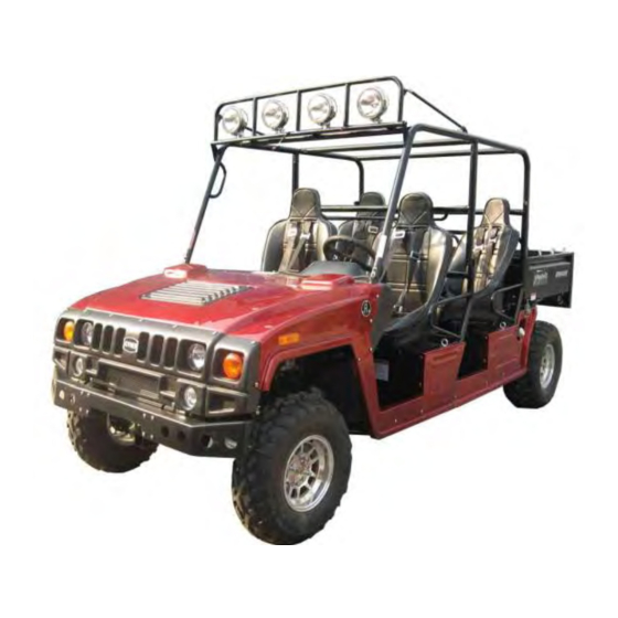
- Page 1 Owner’s manual JNSZ800UV-R4...
- Page 2 INTRODUCTION Thank you for choosing JOYNER JNSZ800UV-R4. It represents the result of many years of JOYNER experience in the production of utility vehicles. With the purchase of this JOYNER, you can now appreciate the high degree of craftsmanship and reliability that have made JOYNER a leader in this field. This manual will provide you with a good basic understanding of the features and operation of this vehicle.
-
Page 14: Table Of Contents
CONTENTS LOCATION OF THE WARNING AND SPECIFICATION LABELS ..............16 SAFETY INFORMATION ............................19 CONTROL FUNCTIONS ............................21 ................................21 AIN SWITCH ................................... 21 AUGES ................................22 WITCHES ..............................21 NDICATOR IGHTS ..................................23 EDAL ............................24 ARKING BRAKE LEVER ............................... - Page 15 LUTCH REPLACEMENT ............................. 51 RONT HEEL LIGNMENT PERIODIC MAINTENANCE ..........................52 MAIN WIRING DIAGRAM ............................ 42 ENGINE WIRING DIAGRAM ..........................43 CONTROL WIRING DIAGRAM ........................... 44 JNSZ800UV-R4 LIMITIED WARRANTY ......................45 ENGINE MECHANICAL SYSTEMS ........................46 ELECTRIC ENJECTION SYSTEMS ........................90...
-
Page 16: Location Of The Warning And Specification Labels
Read and understand all of the labels on your vehicle. They contain important information for safe and proper operation of your vehicle. Never remove any labels from your vehicle. If a label becomes difficult to read or comes off, a replacement label is available from your Joyner dealer. - Page 18 JOYNER S650.09.04.00.10A...
-
Page 19: Safety Information
SAFETY INFORMATION THE SAFETY IS FRIST. Severe injury or death can result if you do not follow these instructions. Read this manual and all labels carefully and follow the operating procedures described: 1. This vehicle is designed to carry the driver and one passenger. Never carry passengers in the cargo bed. - Page 20 19. Always follow proper procedures for going uphill. If you lose momentum and cannot continue up a hill, back down the hill with the engine in reverse gear. Use engine braking to help you go slowly. If necessary, use the brakes gradually to help you go slowly. 20.
-
Page 21: Control Functions
CONTROL FUNCTIONS Main switch Functions of the respective switch positions are as follows: OFF: All electrical circuits are switched off except the turning signal both the left and the right when the light switch is on. The key can be removed in this position. ON 1: All electrical circuits are supplied with power, except the ignition system and fuel system, the headlights and... -
Page 22: Switches
a speedometer (which shows the riding speed) ● a tachometer (which shows the engine rotate speed) ● a voltmeter (which shows the battery charge capacity) ● a coolant thermometer (which shows the coolant temperature) ● a oil pressure gauge (which shows oil pressure) ●... -
Page 23: Indicator Lights
If anyone of them can’t work well, please correct the problem before operating the engine .If you can’t find or solve the problem yourself; please get the help from your JOYNER dealer. -
Page 24: Parking Brake Lever
Parking brake lever Pull the parking lever up so that the unit can engage park brake. To release the unit, press button in the front end of parking lever then push the parking lever to the bottom. Never use parking brake lever when the vehicle don’t stop fully. ... -
Page 25: Seats And Safety Belts
Seats and Safety belts Seats The left seat and the right seat can remove. To move a seat, pull its seat lock lever upward, lift the front of the seat, and then slide the seat forward and up. To repair the engine and the battery conveniently, the seats can be lifted just like the cargo bed . -
Page 26: Glove Compartment
Glove compartment Push down the release button to open the glove compartment. To protect from damage, do not put metal products, like tools or sharply edged products directly in the glove compartment. If they must be stored, wrap them in appropriate cushion material. -
Page 27: Are You Ready To Drive
ARE YOU READY TO DRIVE Before each drive, you need to make sure you and your UV800-R4 are both ready to drive. To help get you prepared, this section discusses how to evaluate your driving readiness, what items you should check on your UV800-R4, and adjustments to make for your comfort, convenience, or safety. -
Page 28: Drive Training
Operating this UV800-R4 without wearing an approved motorcycle helmet, eye protection, and protective clothing could increase your chances of head or eye injury, possibly death in the event of severe accident. Always wear approved motorcycle helmet that fits properly and wear eye protection (goggles or face shield), gloves, boots, long-sleeved shirt or jacket and long pants. -
Page 29: Age Recommendation
Age Recommendation It is strongly recommended that no one under the age of 16 be permitted this UV800-R4 without adult supervision. A child driving a UV800-R4 that is not recommended for his/her age could lose UV800-R4 control and result in severe injury or death. A child under 16 should have adult supervision when operate on the UV800-R4. -
Page 30: Is Your Vehicle Ready To Drive
IS YOUR VEHICLE READY TO DRIVE Before each drive, it is important to inspect your UV800-R4 and make sure any problems you find are corrected. A pre-drive inspection is a must, not only for safety, but because having a breakdown, or even a flat tire, can be a major inconvenience. If your UV800-R4 has overturned or has been involved in a collision, do not drive it until your UV800-R4 has been inspected by your dealer. - Page 31 Leaks, Loose Parts ■ Walk around your UV800-R4 and look for anything that appears unusual, such as a leak or loose cable. Lights ■ Make sure the headlight, brake light and tail light are working properly. Throttle ■ Check the free play and adjust if needed. Press the throttle to make sure it moves smoothly without sticking, and snaps back automatically when it is released.
-
Page 32: Safe Driving Precautions
SAFE DRIVING PRECAUTIONS Off-Road Use Only You’re UV800-R4 and its tires are designed and manufactured for off-road use only, not for pavement. Driving on pavement can affect handling and control. You should not drive your UV800-R4 on pavement. Operating this UV800-R4 on paved surfaces may seriously affect handling and control of the UV800-R4, and may cause the vehicle to go out of control. -
Page 33: Control Speed
Removing hands from Steering wheel or feet from foot controls during operation can reduce your ability to control the UV800-R4. Always keep both hands on the steering wheel and both feet on the foot controls of your UV800-R4 during operation. Control Speed Driving at excessive speed increases the chance of an accident. -
Page 34: Do Not Perform Stunts
Failure to take extra care when operating on excessively rough, slippery or loose terrain could cause loss of traction or vehicle control, which could result in an accident, including an overturn. Do not operate on excessively rough, slippery or loose terrain until you have learned and practiced the skills necessary to control the UV800-R4 on such terrain. -
Page 35: Specifications
SPECIFICATIONS Model JNSZ800UV-R4 Dimensions: Overall length 4045mm Overall width 1550mm Overall height 1900mm Seat height 850mm Wheelbase 2050mm Ground clearance 290mm Minimum turning radius 5500mm Basic weight: With oil and full fuel tank 825kg Engine: Engine type Liquid cooled—4stroke Cylinder arrangement... - Page 36 Chassis Frame type Steel tube frame Caster angle 3º Tire Type Tubeless Size front 27 inch rear 27 inch Brakes: System Front and rear unified Type front Dual disc brake rear Dual disc brake Operation Foot operation Suspension: Front suspension Independent Dual A-Arm Rear suspension Longitudinal Control Arm...
-
Page 37: Operation
OPERATION Operation controls Do not attempt to start or operate the engine until completely familiar with the location and use of each control necessary to operate this vehicle. The operator must know how to stop this machine before starting and driving it. Throttle The right foot pedal is the throttle that controls the UV800-R4 speed. -
Page 38: Clutch
Clutch The left foot pedal controls the clutch cable. With the pedal down, you can shift the shift lever. Improper operation of the clutch will lead to excessive wear of the clutch friction surface. Note: When operating the vehicle, if it does not feel comfortable about one of the three pedals, adjust the bolt and then tighten the nut until it feels very... - Page 39 Before you start the engine, check that the parking brake is engaged, and the gear shift lever is in neutral. Trying to start the engine in gear may damage the starter motor, clutch or gearbox. Release the key at once if the engine starts. Holding the key in start position when the engine is running will cause damage to the starter motor.
-
Page 40: Engine Stop Key
Engine stop key Before driving this vehicle, test the Engine Stop key to assure that it is operating properly. With the engine running, turn the key counterclockwise to the “off” position for the engine to shut down. Pre-Drive Inspection Perform this pre-drive inspection everyday before driving vehicle. If not performed, serious damage to the vehicle or personal injury may result. -
Page 41: Passenger
Passenger The vehicle allows for two riders only. Combined maximum weight of driver and the passenger should not exceed 360kg or 800Ibs. Caution: The passenger should be wearing seat belt all the time. Seat Adjustment The left seat and the right seat can remove. To move a seat, pull its seat lock lever upward, lift the front of the seat, and then slide the seat forward and up. -
Page 42: Parking Adjustment
Parking Adjustment Pull the park brake lever up so that the unit can engage park brake. To release the unit, press button on front end of parking lever then push the parking lever to the bottom. Adjust the parking cable if necessary. Gear Shift Adjustment Before operate the vehicle, check the shift lever as to change gearshift from 1 to 5 and... -
Page 43: Starting And Operating Instructions
Starting and Operating Instructions Before starting the engine, be sure that the driver is seated properly in the UV800 R4 and tighten the seat belts. Testing the UV800 R4 in an open place at the beginning to learn how to start, turn and stop. ... -
Page 44: Check Engine Oil And Recharge
Oil inlet Oil inlet plug Oil measure Oil measure Oil outlet With the engine warm, put the vehicle on the level ground. Shut down the engine; put a collecting oil plate under the engine oil outlet. Loosen the oil outlet plug in the warm engine. Let the engine oil out fully. Tighten the engine oil outlet plug. -
Page 45: Check Transmission Oil
Oil outlet Oil inlet Put the vehicle on the level ground. Shut down the engine; put a collecting oil plate under the transmission oil outlet. Loosen the oil outlet plug in the warm engine. Let the transmission oil out full off highway recreational vehicles. -
Page 46: Idle Speed
4. Increase the engine rev a few times. 5. Repeat 2, 3, 4 till the coolant is at neck and no bubbles come up. 6. Refit the coolant cap, turn it clockwise and tighten it. 7. Turn the reserve coolant case cap counterclockwise and open the cap. 8. -
Page 47: Repair
REPAIR Front Wheel Replacement Do not disassemble the center castle nuts when you replace the front wheels. Tighten the nuts after replacing the wheels. Rear Wheel Replacement Do not disassemble the center castle nuts when you replace the rear wheels. Tighten the nuts after replacing the wheels. -
Page 48: Clutch Replacement
Clutch replacement 1. Remove two bolts, and demount Starter-assembly carefully. Q1840845 Q1841245 S11-3708111 S11-3708110GA 2. Remove four bolts on the transmission case, lay down these carefully. Caution: When fix the four bolts in the transmission case; you must tighten them according to the prescribed torque 45-55N.M. - Page 49 3. Remove upper steel cushions and lower steel cushion. 372-100203 S11-170010 4. Insert a spine-shaft into the hole of the Clutch assy; remove the six bolts on the Clutch pressure plate, now it’s clear. Caution: When fix the six bolts in the Clutch pressure plate; You must tighten them according to the prescribed torque 28 N.M.
- Page 50 S11-1601020 S11-1601030 FIGURE 1 5. Insert a spline-shaft into the hole of the Clutch assy, fix the six bolts on the Clutch pressure plate, and tighten them according to the prescribed torque 28 N.M. 6. Fix parts according to reverse operation to the disassembly.
-
Page 51: Front Wheel Alignment
Front Wheel Alignment a. Put the vehicle on level ground. b. The “toe-in” of the front wheels should be 0.98 inches. To check for alignment, measure distance A and B between the centerline (CL) of the wheels. The proper toe-in dimension A should be 0.98 inches greater than dimension B. -
Page 52: Periodic Maintenance
PERIODIC MAINTENANCE The maintenance intervals in the following table are based upon average driving conditions. Driving in unusually dusty areas, require more frequent servicing. Time of service Initial Monthly Quarterly Yearly Item service Engine 1. Driven belt 2. Tighten bolts on engine. 3. -
Page 53: Main Wiring Diagram
MAIN WIRING DIAGRAM... -
Page 54: Engine Wiring Diagram
ENGINE WIRING DIAGRAM... -
Page 55: Control Wiring Diagram
CONTROL WIRING DIAGRAM... -
Page 56: Jnsz800Uv-R4 Limitied Warranty
This warranty does not apply to any part, which in opinion of seller was defective because of improper maintenance, improper assembly, alterations, abuse, negligence or accident. Should warranty service be required on your JNSZ800UV-R4 during the 90 days warranty period, please contact you’re nearest authorized dealer for repairs. -
Page 57: Engine Mechanical Systems
ENGINE MECHANICAL SYSTEMS... -
Page 101: Electric Enjection Systems
ELECTRIC INJECTION SYSTEM... -
Page 143: Clutch Hydraulic Assembly
22 CLUTCH HYDRAULIC ASSEMBLY Part No. Part Description Comments ZJ610.04-00/19 Master cylinder assy of clutch S800.07.04.01.01-R4 Outlet hose of Master cylinder ZJ610.05-00/22 cylinder Lower of clutch ZJ610.05-05 Ripple boot ZJGS.01-02 Hose bolt M10x1.25 ZJGS.01-01 Seal washer S800.07.04.01.00-R4 Clutch hydraulic pump assembly...
Need help?
Do you have a question about the JNSZ800UV-R4 and is the answer not in the manual?
Questions and answers