Table of Contents
Advertisement
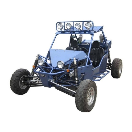
Owner's Manual
JNSZ1100SVB
Repair Manual
Parts manual
READ THIS MANUAL CAREFULLY
IT CONTAINS IMPORTANT SAFETY
INFORMATION.
MINIMUM
16
RECOMMENDED
OPERATOR AGE:
FOR OFF-ROAD USE ONLY
This vehicle is designed and manufactured for off-road use only.
USA only:
It does not confirm to federal motor vehicle safety standards, and operation on
Public streets, roads, or highways is illegal
0
Advertisement
Table of Contents

Related Manuals for Joyner JNSZ1100SVB


Summary of Contents for Joyner JNSZ1100SVB
- Page 1 Owner’s Manual JNSZ1100SVB Repair Manual Parts manual READ THIS MANUAL CAREFULLY IT CONTAINS IMPORTANT SAFETY INFORMATION. MINIMUM RECOMMENDED OPERATOR AGE: FOR OFF-ROAD USE ONLY This vehicle is designed and manufactured for off-road use only. USA only: It does not confirm to federal motor vehicle safety standards, and operation on...
- Page 2 Thank you for choosing JOYNER JNSZ800MVA. It represents the result of many years of JOYNER experience in the production of utility vehicles. With the purchase of this JOYNER, you can now appreciate the high degree of craftsmanship and reliability that have made JOYNER a leader in this field.
-
Page 3: Table Of Contents
CONTENTS Warranty policy ........................ 5 OWNER’S MANUAL ...................... 15 1. FOREWORD ....................... 15 2. A FEW WORDS ABOUT SAFETY ............... 16 3. IMPORTANT SAFETY INFORMATION ............... 16 Follow the Age Recommendation ..................16 Always Wear a Helmet ......................16 Drive Off-Road Only ......................16 Take Time to Learn &... - Page 4 Parts manual ....................... 138 1. ENGINE ......................138 1. COOLING SYSTEM ...................... 138 2. CYLINDER BLOCK ....................... 139 3. CRANKSHAFT ......................140 4.EXHAUST MANIFOLD ....................141 5. INTAKE SYSTEM ......................142 6. LUBRICATING DEVICE ....................144 7. CYLINDER HEAD ......................145 7.
- Page 5 18.Fender relative option ....................197 19.Spotlight relative option ..................... 198 20.Long cobined handle option ..................199 21.Short combined handle option ................... 200 22.Big flag staff mount option ..................201 24.Alum combined pipe clamp option ................203 25.Small flagstaff mount option ..................204 26.Shock absorber coat option ..................
-
Page 6: Warranty Policy
Warranty policy... -
Page 16: Owner's Manual
OWNER’S MANUAL 1. FOREWORD Thank you for choosing our off high way recreational vehicle. We hope you will have fun with it. Before you drive the off high way recreational vehicle, please read through this Owner’s Manual carefully as it contains important safety and maintenance information. -
Page 17: A Few Words About Safety
2. A FEW WORDS ABOUT SAFETY In order to keep everyone safe, you must take responsibility for the safe operation of your Off high way recreational vehicle. To help you make informed decisions about safety, we have provided operating procedures and other information on labels and in this manual. This information alerts you to potential hazards that could hurt you or others. -
Page 18: Take Time To Learn & Practice
Take Time to Learn & Practice Even if you have derived other off high way recreational vehicle, take time to become familiar with how this off high way recreational vehicle works and handles. Practice in a safe area until you build your skills and get accustomed to this off high way recreational vehicle’s size and weight. - Page 19 The labels are considered permanent parts of the Off high way recreational vehicle. If a label comes off or becomes hard to read, contact your dealer for warning labels replacements.
-
Page 20: Are You Ready To Drive
5. ARE YOU READY TO DRIVE? Before each drive, you need to make sure you and your Off high way recreational vehicle are both ready to drive. To help get you prepared, this section discusses how to evaluate your driving readiness, what items you should check on your Off high way recreational vehicle, and adjustments to make for your comfort, convenience, or safety. -
Page 21: Drive Training
Operating this Off high way recreational vehicle without wearing an approved motorcycle helmet, eye protection, and protective clothing could increase your chances of head and/or eye injury, possibly death in the event of severe accident. Always wear approved motorcycle helmet that fits properly and wear eye protection (goggles or face shield), gloves, boots, long-sleeved shirt or jacket and long pants. -
Page 22: No Alcohol Or Drugs
No Alcohol or Drugs Alcohol, drugs and off high way recreational vehicles don’t mix. Even a small amount of alcohol can impair your ability to operate a Off high way recreational vehicle safely. Likewise, drugs-even if prescribed by a physician-can be dangerous while operating a Off high way recreational vehicle. -
Page 23: Safe Driving Precautions
Under body & Exhaust System ■ Check for and remove any dirt, vegetation or other debris that could be fire hazard or interfere with the proper operation of the Off high way recreational vehicle. Air Cleaner Housing Drain Tube ■ Check for deposits in the drain tube. -
Page 24: Keep Hands And Feet On Controls
Operating this Off high way recreational vehicle on public streets, roads or highways can cause collision with other vehicle. Never operate this Off high way recreational vehicle on any public streets, roads or highways, even dirt or gravel one. Keep Hands and Feet on Controls Always keep both hands on the steering wheel and both feet on the foot controls. -
Page 25: Do Not Perform Stunts
Failure to use extra care when Operating this Off high way recreational vehicle on unfamiliar terrain could result in the Off high way recreational vehicle overturning or going out of control. Go slowly and be extra careful when operating on unfamiliar terrain. Always be alert to changing terrain conditions when operating the Off high way recreational vehicle. -
Page 26: Specifications
8. SPECIFICATIONS DIMENSIONS Overall Length------------------------------------------------------------------------------------------------------------123 in. (3130mm) Overall Width ------------------------------------------------------------------------------------------------------------- 75 in. (1910mm) Overall Height ----------------------------------------------------------------------------------------------------------- 69 in. (1745mm) Wheelbase ---------------------------------------------------------------------------------------------------------------- 89 in. (2270mm) Front Track --------------------------------------------------------------------------------------------------------------- 66.5 in. (1690mm) Rear Track -------------------------------------------------------------------------------------------------------------------65 in. (1650mm) Ground Clearance -------------------------------------------------------------------------------------------------------- 12.5 in. (320mm) ENGINE Type ------------------------------------------------------------------------------------------------------- 4-Bore, 4-Stroke, Liquid-cooled Bore x Stroke --------------------------------------------------------------------------------------------------------------- 72mm×66.5mm... -
Page 27: Operation Instruction
9. OPERATION INSTRUCTION WARNING-Do not attempts to start or operate the engine until completely familiar with the location and use of each control necessary to operate this vehicle. Operator must know how to stop this machine before starting and driving it. Control pedal 1) Accelerator Pedal: Changes engine rpm and vehicle ground speed. -
Page 28: Switch
brake lever set. Indicator light will illuminate indicating park brake is engaged. (See figure 2) • Set park brakes: pull-up on the park brake lever until the lever is tight. • Release park brakes: Pull-up on the park brake lever, depress the release button and push the lever 5) Shift Selector: Changes trans-axle gears from neutral to forward or reverse. -
Page 29: Indicating And Gauges
C/215 F. and the Stop engine immediately. Check coolant lever and add if low, see authorized JOYNER dealer if temperature indicator stay on and overflow tank is full of coolant. (See figure 8) 15) Voltmeter: Indicates battery is charging. Check battery if voltmeter registers a charge that is lowers than normal. -
Page 30: Passengers
Speedomete Voltmeter Tachometer Fuel level gauge Oil pressure gauge Coolant temperature indicator FIGURE 8 Coolant temperature light Reverse gear light Battery charge light Oil pressure light FIGURE 9 Passengers The vehicle allows for two riders only. Make sure you brief your passenger on proper safety procedures like keeping hands, arms, feet and other body appendages inside the vehicle. -
Page 31: Maintenance
Chassis Maintenance 1. Tire Maintenance Use only tires recommended by Joyner. It is important for your safety and the safety of others that the tires have correct air pressure. Check air pressure in four tires before each use. Visually inspect tires for loss of air throughout each day of operation. See Tire inflation Chart below for correct tire pressure. - Page 32 Thin nut Thin nut FIGURE 12 3. Parking Adjustment Pull the park brake lever up so that the unit can engage park brake, To release the unit, press button on front end of parking lever then push the parking lever to the bottom. Adjust the parking cable if necessary.
-
Page 33: Shock Adjustment
The speed of vehicle The first 1000 km Gear 25km/h Gear 45km/h Max speed in each gear Gear 70 km/h Gear 100km/h 5. Shock adjustment After a long time use, the shock need to be adjusted for more tension refer to maintenance and service log, adjust the shock with a special spanner. -
Page 34: Clutch Replacement
Castle nuts Torque:180±5 N.M Wheel nuts Torque:70±5 N.M FIGURE 15 7. Rear Wheel Replacement Do not disassemble the center castle nuts when you replace the front wheels. (See Fig. 17) Tighten the nuts after replacing the wheels. Castle nuts Torque:180±5 N.M Wheel nuts Torque:70±5 N.M FIGURE 16... - Page 35 Q1840845 GB/T70.1-2000-M12*1.75*75*25 FIGURE 17 FIGURE 18 S11-3708111 S11-3708110G FIGURE 20 FIGURE 19 2. Remove four bolts on the transmission case, lay down these carefully. Caution: When fix the four bolts in the transmission case; you must tighten them according to the prescribed torque 45-55N.M.
- Page 36 FIGURE 23 FIGURE 24 3. Remove upper steel cushions and lower steel cushion. (See Fig. 26-27) 372-10020301 S11-17001031 FIGURE 25 FIGURE 26 4. Insert a spine-shaft into the hole of the Clutch assy , remove the six bolts on the Clutch pressure plate, now It’s clear.
- Page 37 FIGURE 30 FIGURE 29 FIGURE 31 5. Insert a spline-shaft into the hole of the Clutch assy , fix the six bolts on the Clutch pressure plate , tighten them according to the prescribed torque 28 N.M . (See Fig. 33-34) FIGURE 32 FIGURE 33...
-
Page 38: Front Wheel Alignment
6. Fix parts according to reverse operation to the disassembly. 9. Front Wheel Alignment 1.1. Put the vehicle on level ground. 1.2. The “toe-in” of the front wheels should be 0.63 inches. To check alignment, measure distance A and B between the centerline (CL) of the wheels. The proper toe-in dimension A should be 0.63 inches greater than dimension B. -
Page 39: Storage Instruction
12. Storage Instruction In the event your kart is not to be operated for periods in excess of 30 days or at the end of each driving season prepare for storage as follows: 1.4. Drain fuel tank by allowing engine to run out of fuel, or use a fuel stabilizer. 1.5. - Page 40 Do not drain fuel while engine is hot. Be sure to move Off high way recreational vehicle outside before draining fuel...
- Page 41 13. ENGINE WIRING DIAGRAM...
- Page 42 MAIN WIRING DIAGRAM...
- Page 43 15. Electrical schematic diagram IGN 2 Start motor Ignition switc h Spot light switch 1 I/p wiring conn 23 spot light*4 I/p wiring conn 21 Battery IGN 1 High beam R High beam switch 1 IGN 2 Fuelsensor High beam L oil pressure dipped beam R sensor...
-
Page 44: Engine Maintenance
Engine maintenance 16. Service Air Filter Service air filter refer to preventative log. NOTE: Service more often under dusty conditions. Filter Cover Rubber bushing FIGURE 35 Remove filter cover (See Fig. 36) Check the filter cover and the air filter, if the filter cover and the air filter are dusty, please clear the filter cover and replace with a new air filter. -
Page 45: Transmission Lubrication
Oil outlet FIGURE 37 FIGURE 38 1.6.1. With the engine warm, put the vehicle on the level ground. 1.6.2. Shut down the engine, put a collecting oil plate under the engine oil outlet. Loosen the oil outlet plug in the warm engine. Let the engine oil out fully (see Fig. 9). 1.6.3. - Page 46 (see Fig. 14、15). 1.6.10. Remove the iron dust plug, this plug has a magnet on it. Iron dust caused by moving parts will stick to the plug. Clean the iron dust from this dust plug (see Fig. 16). 1.6.11. Tighten the transmission oil outlet plug and the iron dust plug(see Fig. 16). 1.6.12.
-
Page 47: Idle Speed
Opening the radiator cap while the engine is hot can be hazardous. Opening the radiator cap can spray the high temperature coolant in your eyes, face and any parts of your body. This can result in severe injury. Never open the radiator cap while the engine is hot. New and used coolant can be hazardous. - Page 48 Press the hook down Engine relay Fuel pump relay Fan relay Spot light relay R gear indicator fuse Engine fuse Flash fuse Fuel pump fuse Gauge and indicator fuse ECU normal open circuits fuse Fan fuse Brake indicator fuse...
-
Page 49: Bulb Replacement
Bulb replacement To replace the bulb of the sport light, do the following, see Pic 1-Pic 6: Pic 1 Pic 2 Pic 3 Pic 4 Pic 5 Pic 6 Loose the 2 crews at the bottom of the head light, and take off the 2 hoops around the head light. Separate the head light as the picture. - Page 50 Take off the bulb you need to replace through turning the bulb counter clockwise about a half round, and replace a new one. Put all the parts back with reversing step 1~2.
- Page 51 29. Timing Belt 1. Configuration diagram 1 Water pump pulley 2 Timing belt cover. upper 3 Timing belt cover. Lower 4 Torsion shock absorber 5 Timing pulley damper 6 Tensioner 7 Crankshaft timing pulley .8 Timing belt...
- Page 52 2. Disassembly 2.1. According the right picture, remove water pump pulley Torque: 25±1.5 N.m 2.2. Removing timing belt cover Torque: 6±1N.m 2.3. Remove tensional vibration damper 2.3.1. Fix the flywheel and prevent the gear ring from rotating, 2.3.2. Remove bolt of tensional vibration damper.
- Page 53 2.5. Remove the tensioner 2.5.1. Carry out the operation at the upper thrust point of compression of the first cylinder piston 2.5.2. After removing the timing cover cap, turn the bolt and rotate the timing gear clockwise with wrench, align timing mark of camshaft timing gear with the cam mark of camshaft cover cap;...
- Page 54 2.8. Make careful and detailed checks on the timing belt. Replace with new parts if any of the conditions shown in the figure occurs. 2.8.1. Cracks on the backside rubber; 2.8.2. Cracks of teeth roots, cracks clearing off the fabric lining layer; 2.8.3.
- Page 55 Model EF Item GL、ZL、GS、ZS Diameter of camshaft φ110.7 +0.1 -0.2 timing gear (mm) Diameter crankshaft φ54.65 +0.7 -0.13 timing gear(mm) Baffle of crankshaft timing gear Check to see if there is any deformation Standard size of crankshaft timing gear: Wide 28.6mm 3.
- Page 56 3.3.2. Turn the crankshaft for two circles towards the engine rotating direction, so that the camshaft pulley and the crankshaft pulley match the clockwise marks respectively. 3.3.3. Use hands to press down for about 5mm. The force for pressing the clockwise belt is about: [Reference]...
- Page 57 3.5.2. When there is a flying wheel, 3.5.2.1. Fix the flywheel to prevent the tooth ring from turning 3.5.2.2. Then tighten bolt of tensional vibration damper. 3.6. Install timing belt cover Install seal strip in the position shown as right figure. Install the position 1 and position 2 before cylinder head assembly;...
- Page 58 30. Camshaft 1. Configuration diagram ※:Non-reusable part Unit: N*m (kg*cm) (1) Valve cage cover (2) Valve cage cover gasket (3) Camshaft timing pulley (4) Camshaft cover (5) Circular plug (6) Camshaft bearing cap (7) Exhaust camshaft,(8) Intake camshaft,(9) Oil seal(10) Spring retainer(11) Wave washer(12) Intake camshaft sub-gear(13) Snap ring(14) Lock nut(15) Flange...
- Page 59 2. Removal 2.1. 1) Cover-valve chamber 2) Disassembly order of Cover-valve chamber 2.2. Dismount the timing belt sprocket with a special tool. Attention: Manufacture a special tool according the right figure The special is necessary to prevent the camshaft to rotate Timing mark 2.3.
- Page 60 Air outlet camshaft gear Air inlet camshaft gear Screw 2.3.2. Use bolt to position the master and slave gears on the air inlet camshaft, as shown in the right figure. Attention In order to eliminate the radial force, keep the camshaft in the leveled position before dismounting it (to avoid possible damages caused by excessive radial forces)
- Page 61 driver ring and saddle flip washer. 2.7. Camshaft 2.7.1. Use the caliper to measure the height of the camshaft. If it is below the specified limits, make roper replacement. Camshaft Unit:mm Model ZL、 GL、GS、 Item φ23.0-0.02 -0.033 Standard φ23.0-0.02 -0.033 φ22.9 Limit φ22.9...
- Page 62 3.1.1. Fix the two φ6 holes of the camshaft gear S/A. 3.1.2. Turn the slave gear to the right, match the mark hole on the slave gear with the mark on the master gear, or align the marks on the slave gear with the mark on the master gear;...
- Page 63 3.6. Installation of camshaft head cap Smear the fluid sealant on the camshaft Sealing line head cap section (With oil groove) shown as the right figure. 3.6.1. Tighten the bolts according to the sequences shown as the right figure with the specified torques. 3.6.2.
- Page 64 tighten the timing gear bolt of camshaft according to regulated torque of 100±5N.M. Attention: process special tool according the right figure. 3.9. Installation of cylinder head gasket 3.9.1. Clean the the used cylinder head gasket 3.9.2. Put new one into the groove on the timing-belt cover accurately 3.9.3.
- Page 65 clearance according the right figure 一缸 二缸 三缸 四缸 IN EX IN EX IN EX IN — — O — — 4.4. Rotate camshaft a round, keep the position as the right figure, measure the clearance again. First Second Third Fourth cylinder cylinder...
- Page 66 lifter down with a special tool, and hold it. 4.4.3.1. Move the adjusting washer out with a screwdriver, and then remove the washer with a magnet iron wire from inside. 4.4.3.2. Use a caliper to measure and adjust the thickness of the separation cushion.
-
Page 67: Cylinder Head
4.4.3.5. Rotate camshaft to make cam-top downwards, and the throttle to be pressed down, and then take special tool out 4.4.3.6. Rotate camshaft 2-3 round, and then recheck the valve clearance, if valve clearance can’t get to the standard, repeat4.1-4.4 to adjust the valve clearance. - Page 68 (10) Intake valve(11) Exhaust valve(12) Valve oil seal(13) Valve seat(14) Valve guide 32. Dismounting 1.1. Removal of spark plug 1.2. There are 8 cylinder cover bolts. In the process of removing the cylinder, please follow the sequences shown as the right illustration, loosen the bolts one by one evenly and gently.。...
- Page 69 during the process of clearing. Do not drop filth into the air inlet and the water channel. 33. Routine checks 1.8. Cylinder cover Use the straight knife sharp edge ruler to measure the levelness at various points as shown in the figure. Cylinder cover 0.10mm Air inlet branching pipe surface 0.10 mm 1.9.
- Page 70 shown as the figure. Work out the clearance of the final torn and worn section item standard limit Valve guide — φ5.0 Inside diameter(mm) Valve stem outside — φ5.0 diameter (mm) 0.056 0.07 ~ 0.020mm Spacing (mm) 0.066 ~ 0.08 0.030mm 1.10.3.
- Page 71 diameter to achieve the standard value of the clearing. 1.10.4. Valve mating surface 1.10.4.1. Smear thin layer of red lead powder on the valve-mating surface. Do not turn the valve, and gently drive it in. Check the mating condition and the width of mating line.
- Page 72 corresponding hole on the cylinder head with special use auxiliary tools, smear fluid sealant before pressing, pressing height is shown as the illustration: Attention· Pay attention that the vertical degree of its pressing depth and the cylinder head top surface; ·...
- Page 73 ·Beware of the flying spring and other objects Upon completion of the installation of the throttle springs and throttle spring stands, use special tools to install the locking blocks for the throttle spring stands. 1.11.3.4. Installation of the throttle thrusting rod and throttle spacing by adjusting the separation cushions Install the cylinder cover base,...
-
Page 74: Water Pump
third tightening operation is 70± 3.5 Nm. 1.11.4.3. Installation of the spark plug [Torque] 20±1Nm Attention: The tools should be placed vertically, so as not to make the spark plug insulator become deformed, otherwise it is easy to leak oil. 34. -
Page 75: Oil Pump
Attention: These rings are not reusable. 1.2. Removing the three bolts and dismount the water pump principal body. 1.3. Removal of the dustproof sealing stripe 39. Clearing 1.4. Clearing of the mating surface of the water pump 40. Routine checks 1.5. - Page 76 Non-reusable part ① Oil pan, tighten bolt: 8±2 Nm② Oil strainer③ Oil collector gasket④ Oil pump⑤ Oil pump gasket⑥ Rear oil seal bracket 2. Dismounting 2.1. The engine being turned upside down on the dismounting frame, take off the bolts. Remove the oil pan from the cylinder body.
- Page 77 Attention The filter flange is not reusable. 2.3. Dismount the oil pump assembly and oil pump cushion 2.4. Dismounting of oil seal stand 3. Clearing 3.1. For the mating surfaces of the oil bottom case, oil pump and oil seal stands, For the mating surfaces of the rear oil seal stand and oil pump scraper and chipping chisel or some...
- Page 78 ※:Non-reusable part Unit: N*m (kg*cm) 1 Weather seal2 Oil pump cover plate3 Driven rotor4 Drive rotor5 Split pin6 Relief valve spring seat7 Relief valve spring8 Relief valve9 Crankshaft front oil sealing10 Oil pump body 4.2. Disintegration 4.2.1. Weather seal Attention The weather seal are not reusable.
- Page 79 Attention: Pay attention not to make the spring and spring seat sending forth and ropping suddenly, while taking off the open pins. 4.2.5. Removal of the oil pump pressure relief valve spring stand, spiral spring, oil pump pressure relief valve 4.2.6.
- Page 80 the pump body [Benchmark] 0.10-0.181mm [Limit] 0.25mm 4.3.2. Routine checks on the pressure relief valve 4.3.2.1. Remove the pressure relief valve, there should be no visible tears, wears and scrapes on the pressure relief valve 4.4. Installation After smearing lubricating oil on the 4.4.1.
- Page 81 4.4.3. The marks of the exterior and Mark interior gears of the lubricating oil pump should be on the visible side when being assembled into the pump body. 4.4.4. The new weather seal should be put inside the oil pump cover groove. 5.
- Page 82 5.2. Disintegration 5.2.1. Use a flat screwdriver to remove the rear oil seal. Attention The oil seals are not reusable. 5.3. Checks Check to see if the tears and wears of the lip section of the oil seals are within the normal conditions, and if there are any damages in outer appearance.
- Page 83 6.3. Installation of new lubricating oil collecting and filtering device, oil pump collecting and filtering device [Torque] 6±1N.m 6.4. Assembling of oil pan 6.4.1. Clear the mating surface with the cylinder body 6.4.2. Apply sealing silica before assembling [Grease] Letai 5699 Attention ·The liquid cushion with silica line diameter of ф3-4mm, without any broken section...
-
Page 84: Crankshaft Connecting Rod Mechanism
42. Crankshaft connecting rod mechanism 1. Configuration diagram (Dismount and assemble the oil pump in the follow sequence) ※:Non-reusable part Unit: N*m (kg*cm) (1) Connecting rod cover(2) Connecting rod bearing bush(3) Piston and connecting rod... - Page 85 assembly(4) Main bearing cover(5) Crankshaft(6) Crankshaft bush(7) Thrust washer(8) Cylinder block(9) No.1 compression ring(10) No.2 compression ring(11) Oil ring(12) Piston(13) Connecting rod(14) Piston pin 2. Disintegration of crankshaft connecting rod mechanism 2.1. Check the connecting rod axial clearance 2.1.1. Use centimeter or feeler to measure axial spacing [Benchmark]:0.15-0.24mm [Limit]:0.30mm...
- Page 86 2.2.5. Replace the bush if width is beyond the limit. Attention: Connecting ·In replacing the bushes, you should use the Connecting rod bush rod cover products of same brand and from the same manufacturer, which can accord with the request of clearings. 2.2.6.
- Page 87 crankshaft. [Benchmark]:0.089-0.211mm [Limit]:0.30mm Benchmark item value Thickness of thrust 1.9-0.11 face -0.03 2.4. Check the radial clearance of the crankshaft 2.4.1. Remove the crankshaft bearing cover; use a resin hammer to knock the bearing cover off gently. Clean the inside of the bushes, the 2.4.2.
- Page 88 measure the maximum width of the spacing. If it goes beyond the limit, replace the bush. [Benchmark]:0.025-0.069mm [Limit]:0.10mm 2.4.5. Remove Main bearing cover, Crankshaft, Crankshaft bush, Thru st washer Attention: tighten the bolts fixing bearing cover according the order show as right figure 2.5.
- Page 89 of cleaning to protect your eyes. 2.7.1. Use the old ring to clean the accumulated carbon in the ring groove. 2.7.2. Clean the accumulated carbon at various parts with detergents. Attention Do not use metal brush or some other hard substance to do the cleaning. 45.
- Page 90 hole diameter shown as the following figure, take the minimum value as the size of the pinhole diameter. 2.9.3. Work out the clearance on the basis of the size difference between the hole diameter and the pin diameter. Replace the piston pin or the piston if the result exceeds the benchmark value.
- Page 91 clearance. Benchmark(mm) Limit (mm) Primary ring 0.25-0.40 0.65 Secondary 0.35~0.50 0.65 ring Oil ring 0.20~0.70 1.00 2.9.7. Check the clearance between the Outside diameter piston and the cylinder wall The Measure position positions for measuring the inner diameter of the cylinder and the piston skirt are as shown in the right figure.
- Page 92 turning the crankshaft. 2.10.2. Check the tears and wears of the crankshaft 2.10.2.1. Use a caliper to measure the shaft diameter, and work out the circularity and cylindricity. [Limit] 0.005mm 2.10.2.2. Use a caliper to measure the connecting rod diameter, and work out the circularity and cylindricity.
- Page 93 ring and the oil ring in the following specified procedures. 3.2.1. Install gas ring Side face with marks should be upright, install primary ring with piston ring tool. Install oil ring (gasket ring, down 3.2.2. scraper and upper scraper) firstly, then install the secondary ring, then install the primary ring, Open degree of every ring is shown as the...
- Page 94 shown as the right figure for 2—3 cycles with the specified torque. [Torque] 70±3.5N.m Rotate the crankshaft after 3.3.6. Diameter mark assembling, you should rotate it with ease, the torque should be less than Attention:· The torque of crankshaft rotating should be less than 1Nm;(The torque is for installing the crankshaft only, not for installing the piston connecting rod)
- Page 95 bearing cover and bush according to the following instructions. 3.4.5.1. Smear a little lubricating oil on the bolt and screw nut stand before they are mounted according to the indication mark. 3.4.5.2. Tighten the left and right screw nuts alternately for a couple of times with the specified torque.
- Page 96 46. ELECTRIC INJECTION SYSTE...
-
Page 139: Parts Manual
Parts manual 1. ENGINE 1. COOLING SYSTEM ERP code Part number Name Quantity 02.DLJ.Q1400612 Q1400612 HEXAGON HEAD BOLT WATER PUMP PULLEY 02.DLJ.372-1307014 372-1307014 02.DLJ.Q1840840 Q1840840 HEXAGON FLANGE BOLT BOLT(M8X55) 02.DLJ.Q1840855 Q1840855 02.DLJ.Q1840865 Q1840865 HEXAGON FLANGE BOLT 02.DLJ.372-1307010 372-1307010 WATER PUMP SET 02.DLJ.372-1307015 372-1307015 ‘O’... -
Page 140: Cylinder Block
2. CYLINDER BLOCK No ERP code Part number Name Quantity 02.DLJ.472-1002010 472-1002010 CYLINDER BLOCK ASSY 02.DLJ.372-1002037 372-1002037 POSITION PIN 02.DLJ.372-1002046 372-1002046 CRANKCASE VENTILATION PIPE 02.DLJ.372-1002044 372-1002044 CYLINDER HEAD SEAL PLUG 02.DLJ.Q1840830 Q1840830 HEXAGON FLANGE BOLT 02.DLJ.372-1002060 372-1002060 KNOCK SENSOR 02.DLJ.372-1002036 372-1002036 POSITION PIN 02.DLJ.S11-3810010... -
Page 141: Crankshaft
3. CRANKSHAFT No ERP code Part number Name Quantity 02.DLJ.372-1005031 372-1005031 PULLEY BOLT 02.DLJ.372-1005040 372-1005040 TORSION SHOCK ABSORBER ASSY 02.DLJ.372-1005018 372-1005018 CRANKSHAFT TIMING GEAR 02.DLJ.372-1005017 372-1005017 TOOTHED BELT BAFFLE 02.DLJ.372-1005015 372-1005015 CRANKSHAFT FRONT OIL SEAL 02.DLJ.372-1005033 372-1005033 NEEDLE BEARING 02.DLJ.372-1005032 372-1005032 WOODRUFF KEY 02.DLJ.472-1005010... -
Page 142: Exhaust Manifold
EXHAUST MANIFOLD 2(for Europe) 5 (for Europe) ERP code Part number Name Quantity 02.DLJ.472-1008033 472-1008033 GASKET-EXHAUST MANIFOLD 02.DLJ.472-1008031 472-1008031 EXHAUST MANIFOLD 02.DLJ.Q1200825F3 Q1200825F3 STUD NUT,HEXAGON 02.DLJ.Q33008 Q33008 02.DLJ.472-1008044 472-1008044 HEAT INSULATOR 02.DLJ.Q1460612 Q1460612 BOLT,HEXAGON HEAD 02.DLJ.S11-1205110JA S11-1205110JA OXYGEN SENSOR 02.DLJ.Q1200835F3 Q1200835F3 STUD... -
Page 143: Intake System
02.DLJ.S11-3724863 S11-3724863 BRACKET,OXYGEN SENSOR 5. INTAKE SYSTEM No ERP code Part number Name Quantity 02.DLJ.Q1420625 Q1420625 HEXAGON HEAD BOLT 02.DLJ.S11-1129010J S11-1129010JA THROTTLE 02.DLJ.S11-1129021J S11-1129021JA GASKET-THROTTLE 02.DLJ.Q1840620 Q1840620 HEXAGON FLANGE BOLT 02.DLJ.372-1008043 372-1008043 ACCELERATOR PULLING WIRE BRACKET INTAKE TEMPERATUREAND PRESSURE 02.DLJ.S11-1109411 S11-1109411 SENSOR 02.DLJ.Q1400416... - Page 144 16 02.DLJ.372-1008041 372-1008041 INTAKE MANIFOLD FRONT BRACKET 5. INTAKE SYSTEM No ERP code Part number Name Quantity 17 02.DLJ.372-1008042 372-1008042 INTAKE MANIFOLD REAR BRACKET 18 02.DLJ.472-1014110 472-1014110 BRACKET 19 02.DLJ.Q1400612 Q1400612 HEXAGON HEAD BOLT 10 02.DLJ.472-1014122 472-1014122 CRANKCASE VENTILATION PIPE (2) 21 02.DLJ.481H-1014030 481H-1014030 OIL AND AIR SEPARATOR...
-
Page 145: Lubricating Device
24 02.DLJ.372-1014130 372-1014130 CRANKCASE VENTILATION PIPE (3) 25 02.DLJ.Q1840820 Q1840820 HEXAGON FLANGE BOLT 26 02.DLJ.S11-1108210DA S11-1108210DA CABLE-ACCL. 27 02.DLJ.472-1008012 472-1008012 GASKET-INTAKE MANIFOLD 28 02.TR1100.04.01.01.01 TR1100.04.01.01.01 UPPER INTAKE MANIFOLD 29 02.DLJ.372-1008017 372-1008017 TIE-IN 30 02.DLJ.472-1014123 472-1014123 PIPE 3 31 02.DLJ.S11-1109416BA S11-1109416BA TUBE LUBRICATING DEVICE ERP code... -
Page 146: Cylinder Head
BOLT(M8X55) 02.DLJ.Q1840855 Q1840855 02.DLJ.Q1420612 Q1420612 HEXAGON HEAD BOLT 02.DLJ.372-1010017 372-1010017 OIL STRAINER WASHER 02.DLJ.Q1200616 Q1200616 STUD 02.DLJ.Q33006 Q33006 HEXAGON NUT 02.DLJ.372-1010010 372-1010010 OIL STRAINER ASSY 02.DLJ.Q1840610 Q1840610 HEXAGON FLANGE BOLT 02.DLJ.Q1840830 Q1840830 HEXAGON FLANGE BOLT CYLINDER HEAD No ERP code Part number Name Quantity... -
Page 147: Cylinder Head
11 02.DLJ.472-1003040AB 472-1003040AB GASKET-CYLINDER HEAD 12 02.DLJ.372-1003202RA 372-1003202RA HANGER - FRONT ENGINE 13 02.DLJ.Q1840816 Q1840816 HEXAGON FLANGE BOLT 14 02.DLJ.372-1003067 372-1003067 BLOCK COVER 15 02.DLJ.372-1003066 372-1003066 CAMSHAFT OIL SEAL 02.DLJ.472-1003010 472-1003010 CYLINDER HEAD CYLINDER HEAD ERP code Part number Name Quantity CAMSHAFT BEARING CAP 02.DLJ.372-1003063 372-1003063... -
Page 148: Cover-Valve Chamber
02.DLJ.372-1003038 372-1003038 STUD 02.DLJ.372-1003076 372-1003076 SLEEVE 02.DLJ.372-1003025 372-1003025 PLUG COVER-VALVE CHAMBER No ERP code Part number Name Quantity 02.DLJ.372-1003090 372-1003090 OILING PORT COVER ASSY 02.DLJ.Q2540616 Q2540616 SCREW 02.DLJ.472-1003075 472-1003075 COVER 02.DLJ.472-1003030 472-1003030 VALVE CHAMBER 02.DLJ.472-1003036 472-1003036 GASKET-VALVE CHAMBER 02.DLJ.Q1460625 Q1460625 HEXAGON HEAD BOLT... -
Page 149: Oil Pan
SV1100.04.01.05.01 02.SV1100.04.01.05.01 SPARK PLUG SEAL OIL PAN No ERP code Part number Name Quantity 02.DLJ.472-1009010A 472-1009010A OIL PAN ASSY 02.DLJ.Q1420612 Q1420612 HEXAGON HEAD BOLT SEAL WASHER-OIL DRAIN THREADED 02.DLJ.372-1009017 372-1009017 PLUG 02.DLJ.372-1009014 372-1009014 MAGNET PLUG... -
Page 150: Valve Mechanism
VALVE MECHANISM No ERP code Part number Name Quantity 02.DLJ.372-1007030 372-1007030 TENSIONING PULLEY ASSY 02.DLJ.Q1401045 Q1401045 HEXAGON HEAD BOLT 02.DLJ.Q1400616 Q1400616 HEXAGON HEAD BOLT 02.DLJ.372-1007040 372-1007040 TIMING GEAR COVER ASSY 02.DLJ.Q1460625 Q1460625 HEXAGON HEAD BOLT 02.DLJ.Q1460650 Q1460650 HEXAGON HEAD BOLT 02.DLJ.Q43140 Q43140 SHIELD-SHAFT SPRING RING... -
Page 151: Valve Mechanism
VALVE MECHANISM 9 10 No ERP code Part number Name Quantity 17 02.DLJ.372-1006063 372-1006063 COUPLING FLANGE 18 02.DLJ.372-1006062 372-1006062 EXHAUST CAMSHAFT GEAR 19 02.DLJ.472-1006060 472-1006060 EXHAUST CAMSHAFT GEAR 20 02.DLJ.372-1007017 372-1007017 ADJUSTMENT WASHER 21 02.DLJ.372-1007018 372-1007018 VALVE LIFTER 22 02.DLJ.372-1007019 372-1007019 VALVE LOCK BLOCK 23 02.DLJ.372-1007021 372-1007021 EDDY SLEEVE... -
Page 152: Valve Mechanism
VALVE MECHANISM No ERP code Part number Name Quantity 33 02.DLJ.372-1007014 372-1007014 VALVE SPRING UPPER SEAT 34 02.DLJ.Q673B155 Q673B155 CLAMP 35 02.DLJ.472-1007042 472-1007042 LOWER COVER-TIMING GEAR 36 02.DLJ.480-1011062 480-1011062 BOLT... -
Page 153: Ignition Device
IGNITION DEVICE No ERP code Part number Name Quantity 02.DLJ.S11-3705110JA S11-3705110JA IGNITION COIL 02.DLJ.Q2320525 Q2320525 SCREW AND WASHER UNIT 02.DLJ.S11-3705001CA S11-3705001CA BRACKET-IGNITION COIL 02.DLJ.S11-3707100 S11-3707100 SPARK PLUG ASSY 02.DLJ.Q1460820 Q1460820 HEXAGON HEAD BOLT 02.DLJ.S11-3707020BA S11-3707020BA HI.TENSION CORD NO.1 02.DLJ.S11-3707030BA S11-3707030BA HI.TENSION CORD NO.2 02.DLJ.S11-3707040BA S11-3707040BA HI.TENSION CORD NO.3... -
Page 154: Piston And Connecting Rod Device
PISTON AND CONNECTING ROD DEVICE No ERP code Part number Name Quantity 02.DLJ.372-1004031 372-1004031 PISTON PIN 02.DLJ.372-1004021AC 372-1004021AC PISTON 02.DLJ.372-1004110 372-1004110 CONNECTING ROD ASSY 02.DLJ.372-1004116 372-1004116 BEARING-CONNECTING ROD... -
Page 155: Other Accessory 1
OTHER ACCESSORY 1 No ERP code Part number Name Quantity 02.DLJ.S11-3724180CS-A S11-3724180CS-A Engine Harness 02.DLJ.S11-3605011JA-1 S11-3605010JA-1 472 ECU 02.DLJ.S11-1208210JA S11-1208210JA carbon can PCV 02.DLJ.S11-3708110GA S11-3708110GA Starter assembly 02.DLJ.S11-1700103 S11-1700103 lower Steel cushion 02.DLJ.S11-1200011BA S11-1200011BA Single Exhaust Gasket 03.02.6172,1-M12-R/05 6170-M12*1.75 Hex nut M12*1.75 03.04.93-φ12/05 93-SW12 Spring Washerφ12... -
Page 156: Other Accessory 2
OTHER ACCESSORY 2 No ERP code Part number Name Quantity 02.DLJ.S11-3701110BB S11-3701110BB Alternator Alternator bracket 02.DLJ.S11-3701211BA S11-3701211BA 02.DLJ.S11-1001415BA S11-1001415BA Rear bracket 02.DLJ.S11-3701315 S11-3701315 V-ribbed belt... -
Page 157: T08A2 Transsmission Illustration
2.4T08A2 TRANSSMISSION ILLUSTRATION CASE&ACCESSORY ERP CODE Code name Description 02.DLJ.QR512-1701101 QR512-1701101 CASE.CLUTCH 02.DLJ.4T08A1-1701111 4T08A1-1701111 CASE.TRANSMISSION 02.DLJ.5T07-1701020 5T07-1701020 SIDE COVER 02.DLJ.5T07-1702010 5T07-1702010 DECLUTCH BEARING 02.DLJ.5T07-1702020A 5T07-1702020A DECLUTCH FORK 02.DLJ.5T07-1702004 5T07-1702004 SLEEVE.CLUTCH FORK 2 02.DLJ.5T07-1702030 5T07-1702030 SEAL.CLUTCH FORK 02.DLJ.5T07-1702001 5T07-1702001 SLEEVE.CLUTCH FORK 1 02.DLJ.QR512-1701103 QR512-1701103 DOUBLE-SCREW ROD... - Page 158 1.CASE&ACCESSORY ERP CODE Code name Description 02.DLJ.5T07-3729010 5T07-3729010 SWITCH.BACK-UP LIGHT 02.DLJ.5T07-1701058A 5T07-1701058A DOUBLE-SCREW ROD 02.DLJ.5T07-1701009 5T07-1701009 STOP PLATE.BEARING 02.DLJ.5T07-1701004 5T07-1701004 OIL-STOP PLATE 02.DLJ.GB/T5789-1986 GB/T5789-1986 AM6×12/BOLT AM6X12 02.DLJ.GB/T7246-1987 GB/T7246-1987 6/WASHER 6 02.DLJ.5T07-1701400 5T07-1701400 OIL GROOVE ASSY 02.DLJ.5T07-1702080A 5T07-1702080A ROCKER.CLUTCH 02.DLJ.GB/T5789-1986 GB/T5789-1986 AM8×35/BOLT AM8X35 02.DLJ.GB/T6177-2000 GB/T6177-2000...
-
Page 159: Countershaft
COUNTERSHAFT ERP CODE Code name Description 02.DLJ.4T08A-1701401 4T08A-1701401 COUNTERSHAFT 02.DLJ.QR512-1701410 QR512-1701410 DRIVEN GEAR ASSY.FIRST GEAR 02.DLJ.4T08A1-1701420 4T08A1-1701420 DRIVEN GEAR ASSY.SECOND GEAR 02.DLJ.4T08A1-1701441 4T08A1-1701441 DRIVEN GEAR.THIRD GEAR 02.DLJ.4T08A1-1701461 4T08A1-1701461 DRIVEN GEAR.FOURTH GEAR 02.DLJ.5T07-1701610 5T07-1701610 BEARING.OUTPUT SHAFT.FRONT 5T07-1701240 02.DLJ.5T07-1701240 NEEDLE BEARING.1ST GEAR&2ND GEAR OUTER RING.SYNCHRONIZER.1ST 02.DLJ.QR512-1701439... - Page 160 2.COUNTERSHAFT ERP CODE Code name Description Quantity SPRING.SYNCHRONIZER.1ST 02.DLJ.QR512-1701433 QR512-1701433 GEAR&2ND GEAR GEAR-HUB.SYNCHRONIZER.1ST 02.DLJ.QR512-1701434 QR512-1701434 GEAR&2ND GEAR GEAR-SLEEVE.SYNCHRONIZER.1ST 02.DLJ.QR512-1701431 QR512-1701431 GEAR&2ND GEAR GUIDE BLOCK.SYNCHRONIZER.1ST 02.DLJ.QR512-1701432 QR512-1701432 GEAR&2ND GEAR RETAINER.SYNCHRONIZER.1ST 02.DLJ.5T07-1701205 5T07-1701205 GEAR&2ND GEAR 02.DLJ.5T07-1701202 5T07-1701202 SPACER.3RD GEAR&4TH GEAR 02.DLJ.5T07-1701250 5T07-1701250 REAR BEARING.OUTPUT SHAFT ADJUSTING WASHER.
- Page 161 NPUT SHAFT ASSY No ERP CODE Code name Description 02.DLJ.4T08A1-1701201 4T08A1-1701201 INPUT SHAFT 02.DLJ.5T07-1701080 5T07-1701080 SEAL.INPUT SHAFT 02.DLJ.4T08-1701130 4T08-1701130 BEARING 6204/YA/P63 02.DLJ.4T08A1-1701240 4T08A1-1701240 DRIVE GEAR ASSY.3RD GEAR 02.DLJ.5T07-1701150 5T07-1701150 NEEDLE BEARING.3RD GEAR&4TH GEAR RING.SYNCHRONIZER.3RD GEAR&4TH 02.DLJ.QR512-1701257 QR512-1701257 GEAR&5TH GEAR SYNCHRONIZER ASSY.3RD GEAR&4TH 02.DLJ.QR512-1701250 QR512-1701250 GEAR...
-
Page 162: Input Shaft Assy
3.INPUT SHAFT ASSY No ERP CODE Code name Description WAVEFORM WASHER 02.DLJ.QR512-1701258 QR512-1701258 RING.SYNCHRONIZER 02.DLJ.4T08A1-1701260 4T08A1-1701260 DRIVING GEAR ASSY.4TH GEAR 02.DLJ.5T07-1701110 5T07-1701110 BACK BEARING/INPUT SHAFT 02.DLJ.QR512-1701287 ADJUSTING WASHER. BACK QR512-1701287 BEARING/INPUT SHAFT 02.DLJ.4T08A-1701202 4T08A-1701202 SLEEVE.INPUT SHAFT 02.DLJ.4T08A1-1701200 4T08A1-1701200 INPUT SHAFT ASSY 02.DLJ.QR512-1701298 QR512-1701298 NUT.SYNCHRONIZER.5TH GEAR... -
Page 163: Shift Fork& Shift- Fork Shaft
SHIFT FORK& SHIFT- FORK SHAFT No ERP CODE Code name Description 02.DLJ.QR512-1702311 QR512-1702311 SHIFT FORK.1ST GEAR&2ND GEAR 02.DLJ.5T07-1702041A 5T07-1702041A SHIFT FORK.3RD GEAR&4TH GEAR 02.DLJ.GB/T308-2002 GB/T308-2002 STELL BALL 7.9375 02.DLJ.5T07-1702042A 5T07-1702042A SHIFT FORK.5TH GEAR 02.DLJ.5T07-1702061A 5T07-1702061A SHIFT FORK.3RD GEAR&4TH GEAR 02.DLJ.4T08A-1702001 4T08A-1702001 STOP BLOCK 02.DLJ.QR512-1702231... - Page 164 4.SHIFT FORK& SHIFT- FORK SHAFT No ERP CODE Code name Description 02.DLJ.QR512-1701421 QR512-1701421 SHIFT SHAFT.3RD GEAR&4TH GEAR 02.DLJ.QR512-1702431 QR512-1702431 SHAFT. SHIFT FORK.5TH GEAR 02.DLJ.QR512-1702441 QR512-1702441 SHAFT. SHIFT FORK.REVERSE GEAR 02.DLJ.5T07-1702234 5T07-1702234 SCREW PLUG.SHIFT-FORK SHAFT WASHER. SCREW PLUG.SHIFT-FORK 02.DLJ.5T07-1702233 5T07-1702233 SHAFT 02.DLJ.QR512-1702341 QR512-1702341 SHIFT-FORK PIN.REVERSE GEAR...
-
Page 165: Shift Control Machanism
SHIFT CONTROL MACHANISM Description No ERP CODE Code name 02.DLJ.5T07-1702100A 5T07-1702100A SHIFT-SELECT SHAFT ASSY 02.DLJ.5T07-1702101A 5T07-1702101A SHIFT-SELECTING SHAFT SNAP RING.STOP PLATE.SHIFT 02.DLJ.QR512-1702214 QR512-1702214 INTERLOCK 5T07-1702102 RELEASE-SPRING SEAT.1ST GEAR&2ND 02.DLJ.5T07-1702102 GEAR 5T07-1702103 02.DLJ.5T07-1702103 RELEASE-SPRING.1ST GEAR&2ND GEAR 02.DLJ.5T07-1702104 5T07-1702104 SPRING-STOP PLATE 02.DLJ.5T07-1702107A 5T07-1702107A STOP PLATE.SHIFT INTERLOCK 02.DLJ.5T07-1702105A... - Page 166 5.SHIFT CONTROL MACHANISM Description No ERP CODE Code name 02.DLJ.5T07-1702109A 5T07-1702109A LIMITING SPRING.REVERSE GEAR 02.DLJ.QR512-1702111A QR512-1702111A LIMITING CAM.REVERSE GEAR 02.DLJ.GB/T879,1-2000 GB/T879.1-2000 PIN 5X22 GUIDE CASE ASSY. SHIFT-SELECT 02.DLJ.5T07-1702070A 5T07-1702070A SHAFT 02.DLJ.5T07-1702071A 5T07-1702071A GUIDE CASE. SHIFT-SELECT SHAFT STOP PLATE.RELEASE 02.DLJ.5T07-1702072 5T07-1702072 SPRING.5TH@REVERSE 02.DLJ.GB/T5789-1986 GB/T5789-1986...
- Page 167 5.SHIFT CONTROL MACHANISM No ERP CODE Code name Description WASHER.STOP SCREW.REVERSE 02.DLJ.QR512-1702229 QR512-1702229 GEAR 02.DLJ.GB/T5789-1986 GB/T5789-1986 BOLT AM 8X80 02.DLJ.5T07-1702063 5T07-1702063 PUSHING BLOCK.SHIFT ANTI-DUST COVER.SHIFT-SELECT 02.DLJ.5T07-1702062 5T07-1702062 SHAFT 03.02.6170-M8/05 6170-M8 NUT M8 03.05. 93-Φ8/05 93-Φ8 Spring washer 8 02.DLJ.5T07-1702046 5T07-1702046 BIG WASHER.SHIFT ARM 02.DLJ.5T07-1702045 5T07-1702045...
-
Page 168: Driven Gear Assy.speed Reducer
6.DRIVEN GEAR ASSY.SPEED REDUCER Description No ERP CODE Code name 02.DLJ.4T08A2-1701308 4T08A2-1701308 Differential case 02.DLJ.4T08A-1701604 4T08A-1701604 DRIVEN GEAR.SPEED REDUCER 02.DLJ.5T07-1701010 5T07-1701010 Differential seal assy (left) 02.DLJ.5T07-1701310 5T07-1701310 FRONT BEARING 6007 02.DLJ.QR512-1701604 QR512-1701604 DRIVING GEAR.ODOMETER 02.DLJ.GB/T879,1-2000 GB/T879.1-2000 Needle bearing D5×36 02.DLJ.5T07-1701090 5T07-1701090 Differential seal assy (right) 02.DLJ.5T07-1701309... - Page 169 6.DRIVEN GEAR ASSY.SPEED REDUCER 02.DLJ.5T07-1701306 5T07-1701306 Half axle adjusting washer 02.DLJ.5T07-1701320 5T07-1701320 REAR BEARING 6207 02.DLJ.5T12H-1709506 5T12H-1709506 limited-thrust ring 02.DLJ.4T08A2-1701611 4T08A2-1701611 output shaft 02.DLJ.MQC4-2303016 MQC4-2303016 RETAINER RING 02.DLJ.4T08A2-1701600 4T08A2-1701600 Differential assy...
-
Page 170: Frame,Aluminium Board
3.CHASSIS 1.Frame,aluminium board frame ,aluminium board ERP Code Code name Description Q'ty... - Page 171 02.SVB1100.01.01 SVB1100.01.01.00.00 Frame component 02.SVA1100.01.02.0021 SVA1100.01.02.00.21 front motherboard 02.SVA1100.01.02.0022 SVA1100.01.02.00.22 pedal board 02.SVA1100.01.02.0023 SVA1100.01.02.00.23 seat board 02.SVA1100.01.02.0024 SVA1100.01.02.00.24 engine board 02.SVB1100.01.02.0025 SVB1100.01.02.00.25 left side board 02.SVB1100.01.02.0026 SVB1100.01.02.00.26 right side board 02.SVB1100.01.02.05A SVB1100.01.02.05.00A rear protecting board 03.01.D818-M6X16 D818-M6X16 Cross head screw M6X16 02.JD.0900008 JD0900008 Washer 6...
-
Page 172: Engine Mount Assy
2.Engine mount assy Engine mount assy ERP Code Code name Description Q'ty 02.SV800.04.01.02 SV800.04.01.02.00 front engine mount 03.03.95-Φ10X20X2/05 95-Φ10X20X2 asherΦ10X20X2 03.05.93-Φ10/05 93-Φ10 spring asher Φ10 03.01.5787-M10X30/05 5787-M10X1.5X30 bolt-asher M10X1.5X30 02.D650.04.01.0001 D650.04.01.00.01 engine rubber bumper 03.02.2842-M10X1.25/05 2842-M10X1.25 nut-asher M10x1.25 02.DLJ. 472-0000E 01AA SV1100.04.01.05.00 engine(472) 02.SV800.04.01.03... -
Page 173: Gear -Shift Mechanism
3.Gear -shift mechanism Gear-shift mechanism ERP Code Code name Description Q'ty 03.01.5787-M6X12/05 5787-M6X12 M6X12 bolt 02.SV800.05.02.0001A SV800.05.02.00.01A plastic cover 02.S650.05.02.01 S650.05.02.01.00 shifter control assembly 02.S650.05.02.01.01 S650.05.02.01.01 rubber shifter indication 02.S650.05.02.01.02 S650.05.02.01.02 rubber shifter cover 02.S650.05.02.01.03 S650.05.02.01.03 control framework 02.SV800.05.02.0005 SV800.05.02.00.05 orientation metal sheet 03.02.2842-M6/05 2842-M6... -
Page 174: Steering Assy
4.Steering assy Steering assy 13 14 29 30 3132 33 34 35 23 24 25 42 41 20 21 No. ERP Code Code name Description Q'ty 03.01.70,2-M6X20 70.2-M6X20 M6X20 screw 02.TR1100.05.01.0002-3 TR1100.05.01.00.02-3 plastic cover 02.TR1100.05.01.0002 TR1100.05.01.00.02 350steering wheel 03.02.6183,1-M6/05 6183.1-M6 M6 self-locking nut 02.TR1100.05.01 TR1100.05.01.00.00... - Page 175 02.276-B61902 276-B61902 61902 bearing 02.D800.05.01.01.02 D800.05.01.01.02 steering column housing 02.276-B61803 276-B61803 61803 bearing 03.09.893,22-Φ28 893.2-Φ28 circlip Φ28, internal 03.09.894,1-Φ15 894.1-Φ15 Φ15, external circlip 02.D800.05.01.01 D800.05.01.01.00 steering column assy 03.02.2842-M10X1,25/05 2842-M10X1.25 M10X1.25 nut 03.01.5787-M10X1,25X25/05 5787-M10X1.25X25 M10X1.25X25 bolt 03.03.95-Φ8X24X2/05 96-Φ8X24X2 Φ8 washer(8.4X24X2) 03.05.93-Φ8 93-Φ8 Φ8 spring shim...
-
Page 176: Throttle And Park Assy
5.Throttle and park assy Throttle and park assy 16 17 38 36 Code name Code name Description Q'ty 03.01.5787-M8X20/05 5787-M8X20 Bolt-washer M8X20 02.SV800.07.01.01 SV800.07.01.01.00 four caliper hydraulic brake assy 03.01.5787-M6X20/05 5787-M6X20 Bolt-washer M6X20 02.D1600.01.02.0008 D1600.01.02.00.08 support 03.02.2842-M6/05 2842-M6 nut M6 03.01.5787-M6X20/05 5787-M6X20 Bolt-washer M6X20... - Page 177 02.D650.07.01.0004A D650.07.01.00.04A pushing bar 03.02.6172,1-M8/05 6172.1-M8 nut M8 02.D650.07.01.00.03 D650.07.01.00.03 push rod holder 03.08.91-φ3,2X30/05 91-φ3,2X30 cotter pin 3.2X30 03.03.95-Φ10X28X2/05 95-Φ10X28X2 washer(Φ10.5XΦ18XΦ1.6) 02.SV1100.07.04.02 SV1100.07.04.02.00 clutch pedal 02.D650.07.01.0005 D650.07.01.00.05 pedal rubber cover 02.SV800.07.04.01 SV800.07.04.01.00 cable, clutch 03.01.70,1-M6X55/05 70.1-M6X55 M6X55 socket head bolt 03.02.6172,1-M6/05 6172.1-M6 M6 nut(m=5.2)
-
Page 178: Parking Brake Assy
6.Parking brake assy parking brake assy ERP Code Code name Description Q'ty 02.SV800.07.01.01.01 SV800.07.01.01.01 disc brake with floating caliper,front 02.SV800.07.01.01.02 SV800.07.01.01.02 disc brake with floating caliper,rear 02.ZJ610.04-00/14 ZJ610.04-00/14 Master cylinder assy 02.D650.07.01.00.04 D650.07.01.00.04 Master cylinder rod 02.ZJ509.03-04 ZJ509.03-04 hydraulic brake pads 02.SVB1100.07.02.03.01 SVB1100.07.02.03.01 hydraulic parking brake hose,middle... -
Page 179: Brake Assy
7.brake assy brake assy ERP Code Code name Description Q'ty 02.SV800.07.01.01.01 SV800.07.01.01.01 disc brake with floating caliper,front 02.SV800.07.01.01.02 SV800.07.01.01.02 disc brake with floating caliper,rear 02.DN250.04.01.01 DN250.04.01.01.00 Master cylinder assy 02.JK613B JK613B hydraulic power brake valve 4 set 02.ZJ509.03-04 ZJ509.03-04 hydraulic brake pads 02.ZJ609.F02-01 ZJ609.F02-01 hydraulic threeway valve... -
Page 180: Front Susp Assy
8.Front susp assy Front susp assy 15 17 36353433 17 15 13 11 33343536 14 12 ERP Code Code name Description Q'ty 02.S650.03.01.0002 S650.03.01.00.02 M12X1.5 wheel nut 02.JD.0360010 JD0360010 rubber dirt-proof boot 02.S650.03.01.01A S650.03.01.01.00A left wheel(27X8-12) 03.08.91-φ4X40/05 91-φ4X40 cotter pin φ4X40 03.02.9457-M18X1,5/05 9457-M18X1.5 castle nutM18X1.5... - Page 181 02.D800.03.01.0005 D800.03.01.00.05 30X62X16 ball bearing 02.D800.03.01.0009 D800.03.01.00.09 40x62x7 grease seal 03.01.5782-M16X85/05 5782-M16X85 M16X85 bolt 02.D800.02.01.0002 D800.02.01.00.02 bushing 02.D800.02.01.02 D800.02.01.02.00 upper suspension arm,left 02.D800.02.01.0001 D800.02.01.00.01 radial bearing 03.09.893,2-φ42 893.2-42 circlip φ42 02.D800.02.01.0002 D800.02.01.00.02 bushing 03.02.6185,1-M16/05 6185.1-M16 M16 nut 02.D800.03.01.0002A D800.03.01.00.02A front axle left wheel 02.D800.02.01.01 D800.02.01.01.00 lower suspension arm,left...
-
Page 182: Fuel Tank And Gasoline Pump
9.Fuel tank and gasoline pump Fuel tank and gasoline pump No. ERP Code Code name Description Q'ty 02.SVB1100.04.03.01 SVB1100.04.03.01.00 fuel tank 02.SR2000.04.03.0003A SR2000.04.03.00.03A fuel tank cap 02. SR2000.04.03.03 SR2000.04.03.03.00 fuel level sensor 02.SR2000.04.03.03.01 SR2000.04.03.03.01 rubber washer 02.D650.04.03.0004 D650.04.03.00.04 hoop (10-16) 0.2meter 02.FTCARB-0816 FTCARB-0816... - Page 183 02.SV1100.04.03.0004 SV1100.04.03.00.04 fuel hose(φ16xφ21) 02.D650.04.03.0010 D650.04.03.00.10 fuel filter clip M6X30 cross groove 03.01.D818-M6X30 818-M6X30 head screw 03.03.95-φ6X13X1,5/05 95-φ6X13X1,5 washer φ6X13X1,5 03.05.93-Φ6/05 93-Φ6 spring washer Ф6 03.02.6172,1-M6/05 6172,1-M6 hex nut M6 M6X50 cross groove 03.01.D818-M6X50 818-M6X50 head screw 02.D1600.04.03.02 D1600.04.03.02.00 fuel pump 1.5meter 02.
-
Page 184: Muffler
10.Muffler MUFFLER No. ERP Code Code name Description Q'ty 02.DLJ.472-1008033 472-1008033 exhaust manifold gasket 02.SV1100.04.04.03 SV1100.04.04.03.00 exhaust manifold 02.DLJ.S11-1205110JA S11-1205110JA oxygen sensor 02.SV1100.04.04.04 SV1100.04.04.04.00 seal washer 03.01.5787- M8X35/05 5787- M8X35 nut-washer 02.SV1100.04.04.02A SV1100.04.04.02.00A catalac convertor 02.DLJ.S11-1205110JA S11-1205110JA oxygen sensor 03.02.6183,1-M8/05 6183,1-M8 self-locking nut M8 02.D650.04.04.0008... - Page 185 02.D650.04.04.0008-2 D650.04.04.00.08-2 U clamp screw rod 02.D650.04.04.01B D650.04.04.01.00B long muffler 03.01.5787-M8X30/05 5787-M8X30 bolt-washer M8*30 02.JD.1910002A JD1910002A muffler rubber cover 02.JD.1910002 JD1910002 spacer 03.03.95-Φ8X24X2 95-Φ8X24X2 washer Φ8X24X2 03.02.6183,1-M8/05 6183,1-M8 M8 self-locking nut 02.SV800.01.02.0003 SV800.01.02.00.03 muffler bracket 03.01.5787-M8X25/05 5787-M8X25 bolt-washer M8*25 03.02.6183,1-M8/05 6183,1-M8 M8 self-locking nut 03.03.95-Φ8X24X2...
-
Page 186: Rear Susp Left
11.Rear susp left 27 29 No. ERP Code Code name Description Q'ty 02.S650.03.01.0002 S650.03.01.00.02 wheel nut M12X1.5 02.S650.03.02.01A S650.03.02.01.00A wheel(27X11-12),BL 03.08.91-φ4X40/05 91-φ4X40 cotter pin 4X40 02.DLJ.JGC2202-K JGC2202-K slotted nut M22X1.5,rear shaft 02.D650.03.02.0004A D650.03.02.00.04A disk base 02.D650.03.02.0003A D650.03.02.00.03A M12X1.5 bolt 02.D650.03.02.0005 D650.03.02.00.05 brake disk 02.D650.03.02.0008... - Page 187 02.DLJ.BT-1045 BT-1045 outer boot seal 02.DLJ2303016 2303016 steel cable baffle ring 02.DLJ.SH07680 SH07680 BIG band 02.DLJ.BT-1085 BT-1085 inner boot seal 02.DLJ.SH07350 SH07350 SMALL band 02.DLJ.PT SZW5008 PT SZW5008 end motion type inboard joint 02.DLJ.PT SZ-9035 PT SZ-9035 solid bar,left 02.DLJ.PT SZW1003 PT SZW1003 fixed enter type outboard joint 02.SV800.03.02.01...
-
Page 188: Rear Susp,Right
12.Rear susp,right Rear susp,right 30 31 32 33 32 31 34 No. ERP Code Code name Description Q'ty 02.S650.03.01.0002 S650.03.02.00.02 wheel nut M12X1.5 02.S650.03.02.04A S650.03.02.04.00A wheel(27X11-12),BR (F938) 03.08.91-φ4X40/05 91-φ4X40 cotter pin 4X40 02.DLJ.JGC2202-K JGC2202-K slotted nut M22X1.5,rear shaft 02.D650.03.02.0004A D650.03.02.00.04A disk base 02.D650.03.02.0003A D650.03.02.00.03A... - Page 189 02.DLJ.BT-1085 BT-1085 inner boot seal 02.DLJ.SH07350 SH07350 small band 02.DLJ.BT-1045 BT-1045 outer boot seal 02.DLJ.SH07680 SH07680 big band 02.DLJ.PT SZW1003 PT SZW1003 fixed enter type outboard joint 02.DLJ.PT SZ-9036 PT SZ-9036 solid bar,right 02.DLJ.PT SZW5008 PT SZW5008 end motion type inboard joint 02.DLJ.2303016 2303016 steel cable baffle ring...
-
Page 190: Cooling Cycle
13.Cooling cycle cooling cycle 16 15 38 39 38 39 37 38 39 ERP Code Code name Description Q'ty 03.01.D818-M6*16 818-M6X16 Cross head screw M6*16... - Page 191 02.D650.04.07.0003 D650.04.07.00.03 cover, oil separator 02.D650.04.07.0002 D650.04.07.00.02 air filter, oil separator 02.SV800.04.07.0001 SV800.04.07.00.01 hoop(21-38) 02.D1600.04.01.06 D1600.04.01.06.00 oil separator 03.01.5787-M8X20/05 5787-M8X20 bolt-washer M8*20 03.02.6183,1-M8/05 6183,1-M8 self-locking nut M8 02.SV1100.04.07.0001 SV1100.04.07.00.01 Hose clip(19-29) 02.SVB1100.04.02.03.02 SVB1100.04.02.03.02 water inlet hose 2, engine 02.S650.04.02.02 S650.04.02.02.00 Tee branch 02.SVB1100.04.02.03.01 SVB1100.04.02.03.01...
-
Page 192: Electical Appliance
14.Electical appliance Electrical appliance ERP Code Code name Description Q'ty 02.D1600.06.11A D1600.06.11.00.00A headlight 02.D1600.06.11.0001 D1600.06.11.00.01 headlight bulb... - Page 193 02.D650.06.00.05 D650.06.00.05.00 front turning light,left 02.D650.06.00.15 D650.06.00.15.00 front turning light,right 02.D650.06.00.09 D650.06.00.09.00 horn 02.D25007914A D25007914A flasher apparatus 02.D25007924 D25007924 flasher coat 02.JD.0460003 JD0460003 washer 02.DS250.10.000005 DS250.10.00.00.05 horn button 02.D1600.06.03A D1600.06.03.00.00A switch assy 02.MV800.06.02 MV800.06.02.00.00 speedometer 02.D1600.06.05 D1600.06.05.00.00 tachometer 02.MV800.06.03 MV800.06.03.00.00 Coolant temperature indicator 02.D1600.06.09 D1600.06.09.00.00...
-
Page 194: Fin Assy,Front Cover
15.Fin assy,front cover fin assy,front cover 1 2 3 No. ERP Code Code name Description Q'ty 03.01.D818-M6X16 818-M6X16 Cross head screw M6X16 02.JD0900008 JD0900008 Washer 6 03.02.6183,1-M6/05 6183.1-M6 Self-locking nut M6 02.SVA1100.01.02.0001 SVA1100.01.02.00.01 front cover plate 02.SVA1100.01.02.02.03 SVA1100.01.02.02.03 right side fin 02.SVA1100.01.02.02.04 SVA1100.01.02.02.04 rear panel... - Page 195 02.JD.0900008 JD0900008-W6 Washer 6 03.02.6183,1-M6/05 6183.1-M6 Self-locking nut M6 03.10.12618-4X10 12618-4X10 rivet 4X10 03.01.D818-M6X16 818-M6X16 Cross head screw M6X16 02.JD0900008 JD0900008 Washer 6 03.02.6183,1-M6/05 6183.1-M6 Self-locking nut M6 12618-4X10 03.10.12618-4X10 rivet 4X10 03.10.12618-4X10 12618-4X10 rivet 4X10 02.SVA1100.01.02.02.07 SVA1100.01.02.02.07 fin assy...
-
Page 196: Seat And Safety Belt
16.Seat and safety belt seat and safety belt No. ERP Code Code name Description Q'ty 02.SV1100.08.01.18 SV1100.08.01.18.00 safty belt 02.D650.08.01.0013 D650.08.01.00.13 safty belt tube 02.TR1100.09.01.02 TR1100.09.01.02.00 seat04 02.TR1100.09.01.02.01 TR1100.09.01.02.01 Track with release lever 02.TR1100.09.01.02.02 TR1100.09.01.02.02 Track without release lever... -
Page 197: Rack Relative Option
17.Rack relative option rack No. ERP Code Code name Description Q’ty 02.SVB1100.01.02.03 SVB1100.01.02.03.00 aluminium roof rack 03.01.5787-M10X35 /05 5787-M10X35 bolt-washer M10X35 02.D1600.01.02.0007 D1600.01.02.00.07 spacer 03.02.2842-M10/05 2842-M10 nut M10 Rack relative option 1set 02.SVB1100.10.03 SVB1100.10.03.00.00... -
Page 198: Fender Relative Option
18.Fender relative option FENDER OPTION No. ERP Code Code name Description Q'ty 02.C650.08.01.13 C650.08.01.13.00 fender 02.C1100.02.01.02 C1100.02.01.02.00 upper arm.left.front 02.C1100.02.01.03 C1100.02.01.03.00 upper arm.left.right 02.C1100.02.02.02 C1100.02.02.02.00 rear arm.left 02.C1100.08.01.03 C1100.08.01.03.00 fender bracket.left.front 02.C1100.08.01.04 C1100.08.01.04.00 fender bracket.right.front 02.C1100.08.01.05 C1100.08.01.05.00 fender bracket.left.rear 02.C1100.08.01.06 C1100.08.01.06.00 fender bracket.right.rear 03.01.D818-M6x 16... -
Page 199: Spotlight Relative Option
02.SVB1100.10.01 SVB1100.10.01.00.00 Fender relative option 1set 19.Spotlight relative option SPOTLIGHT OPTION ERP Code Code name Description Q'ty 02.D1600.06.10A D1600.06.10.00.00A spotlight 02.D1600.06.10.0001 D1600.06.10.0001 Spotlight bulb(30W) 03.03.95-φ0X20X1,5/05 95-φ10X20X1,5 washer-φ10X20X1,5 02.SV800.99.99.04 SV800.99.99.04.00 mount of spotlight 03.01.5787-M10*20/05 5787-M10*20 bolt-washer M10*20 03.02.2842-M10X1,25/05 2842-M10X1,25 nut-M10X1,25 03.02.2842-M10/05 2842-M10 nut-M10 1 set... -
Page 200: Long Cobined Handle Option
20.Long cobined handle option ERP Code Code name Description Q'ty 02.SVB1100.08.05.01A SVB1100.08.05.01.00A Long combined handle (Polishing) 02.SVB1100.08.05.01B SVB1100.08.05.01.00B Long combined handle(Anodizing) 02.SVB1100.08.05.01.01A SVB1100.08.05.01.01A LONG HANDLE upper fixed(Polishing) 02.SVB1100.08.05.01.01B SVB1100.08.05.01.01B LONG HANDLE upper fixed(Anodizing) 02.SVB1100.08.05.01.02A SVB1100.08.05.01.02A LONG HANDLE lower fixed(Polishing) 02.SVB1100.08.05.01.02B SVB1100.08.05.01.02B LONG HANDLE lower fixed(Anodizing)... -
Page 201: Short Combined Handle Option
21.Short combined handle option ERP Code Code name Description Q'ty 02.SVB1100.08.05.03A SVB1100.08.05.03.00A Short combined handle (Polishing) 02.SVB1100.08.05.03B SVB1100.08.05.03.00B Short combined handle (Anodizing) 02.SVB1100.08.05.01.01A SVB1100.08.05.01.01A LONG HANDLE upper fixed(Polishing) 02.SVB1100.08.05.01.01B SVB1100.08.05.01.01B LONG HANDLE upper fixed(Anodizing) 02.SVB1100.08.05.01.02A SVB1100.08.05.01.02A LONG HANDLE lower fixed(Polishing) 02.SVB1100.08.05.01.02B SVB1100.08.05.01.02B LONG HANDLE lower fixed(Anodizing)... -
Page 202: Big Flag Staff Mount Option
22.Big flag staff mount option ERP Code Code name Description Q'ty 1set 02.SVB1100.08.05.02A SVB1100.08.05.02.00A BIG FLAGSTAFF MOUNT(Polishing) 1set 02.SVB1100.08.05.02B SVB1100.08.05.02.00B BIG FLAGSTAFF MOUNT(Anodizing) 02.SVB1100.08.05.02.01A SVB1100.08.05.02.01A FLAGSTAFF seat(Polishing) 02.SVB1100.08.05.02.01B SVB1100.08.05.02.01B FLAGSTAFF seat(Anodizing) 02.SVB1100.08.05.02.02A SVB1100.08.05.02.02A BIG FLAGSTAFF upper fixed (Polishing) FLAGSTAFF upper fixed 02.SVB1100.08.05.02.02B SVB1100.08.05.02.02B... - Page 203 03.01.80-M4X12/05 80-M4X12 socket dent holding screw(standardized) 23.Alum combined handle option ERP Code Code name Description Q'ty 1set 02.SVB1100.08.05.05A SVB1100.08.05.05.00A Alum combined handle(Polishing) 1set 02.SVB1100.08.05.05B SVB1100.08.05.05.00B Alum combined handle(Anodizing) 02.SVB1100.08.05.05.01A SVB1100.08.05.05.01A foot seat(Polishing) 02.SVB1100.08.05.05.01B SVB1100.08.05.05.01B foot seat(Anodizing) 02.SVB1100.08.05.05.02A SVB1100.08.05.05.02A foot tube(Polishing) 02.SVB1100.08.05.05.02B SVB1100.08.05.05.02B foot tube(Anodizing)...
-
Page 204: Alum Combined Pipe Clamp Option
24.Alum combined pipe clamp option ERP Code Code name Description Q'ty 02.SVB1100.08.05.04A SVB1100.08.05.04.00A ALUM COMBINED PIPE CLAMP 1set 02.SVB1100.08.05.04B SVB1100.08.05.04.00B ALUM COMBINED PIPE CLAMP 1set 02.SVB1100.08.05.04.01A SVB1100.08.05.04.01A upper tubing clip 02.SVB1100.08.05.04.01B SVB1100.08.05.04.01B upper tubing clip 02.SVB1100.08.05.04.02A SVB1100.08.05.04.02A lower tubing clip 02.SVB1100.08.05.04.02B SVB1100.08.05.04.02B lower tubing clip... -
Page 205: Small Flagstaff Mount Option
25.Small flagstaff mount option Code Code name Description Q'ty 02.SVB1100.08.05.0 SVB1100.08.05.06 SMALL FLAGSTAFF MOUNT(Polishing) 1set .00A 02.SVB1100.08.05.0 SVB1100.08.05.06 SMALL FLAGSTAFF MOUNT(Anodizing) .00B 02.SVB1100.08.05.0 SVB1100.08.05.02 FLAGSTAFF seat(Polishing) 2.01A .01A 02.SVB1100.08.05.0 SVB1100.08.05.02 FLAGSTAFF seat(Anodizing) 2.01B .01B 02.SVB1100.08.05.0 SVB1100.08.05.06 SMALL FLAGSTAFF fixed(Polishing)... -
Page 206: Shock Absorber Coat Option
6.01A .01A 02.SVB1100.08.05.0 SVB1100.08.05.06 SMALL FLAGSTAFF fixed(Anodizing) 6.01B .01B 26.Shock absorber coat option ERP Code Part No. Part Description 02. D800.08.01.00.04-1 D800.08.01.00.04-1 Front shock absorber coat 02. D800.08.01.00.04-2 D800.08.01.00.04-2 Rear shock absorber coat... -
Page 207: Tools And Bag Kit Option
27.Tools and bag kit option ERP Code Part No. Part Description D650.08.05.00.01 Open-jawed spanner 8~10 02.D650.08.05.0001 D650.08.05.00.02 Open-jawed spanner 12~14 02.D650.08.05.0002 D650.08.05.00.03 Open-jawed spanner 13~16 02.D650.08.05.0003 D650.08.05.00.04 Open-jawed spanner 17~19 02.D650.08.05.0004 JD1400004 Thread-locking anaerobic adhesive 02.JD.1400004 D650.08.05.00.06 “-”Screwdriver 02.D650.08.05.0006 D650.08.05.00.07 “+”... -
Page 208: Envelopment And Foam Cover Option
28.Envelopment and foam cover option ERP Code Part No. Part Description SV800.08.01.02.01 Protect-jacket front, upper 02. SV800.08.01.02.01 SV800.08.01.02.02 Protect-jacket side,upper 02. SV800.08.01.02.02 SV800.08.01.02.03 Protect-jacket srear,upper 02. SV800.08.01.02.03 SV800.08.01.02.04 Protect-jacket side,front 02. SV800.08.01.02.04 SV800.08.01.02.05 Protect-jacket middle,upper 02. SV800.08.01.02.05 D250.11770 foam cover 02. -
Page 209: Luxury Absorber Shock Option
29. luxury absorber shock option ERP Code Part No. Part Description 02. SV1100.02.03.01A SV1100.02.03.01.00A front luxury absorber shock 02. SV1100.02.03.02A SV1100.02.03.02.00A Rear luxury absorber shock... -
Page 210: Wearing Parts
Wearing parts 1. Body English name Erp code Part name rubber washer Φ6 02.JD.0900008 JD0900008 radial bearing GE25C 02.D800.02.01.0001 D800.02.01.00.01 bushing 02.D800.02.01.0002 D800.02.01.00.02 rod end bearing POSA16,control arm 02.D800.02.01.0003 D800.02.01.00.03 spacer sleeveφ16 ,control arm 02.D800.02.01.0004 D800.02.01.00.04 interner circlip φ55 (model B) 03.09.893,2-φ55 893.2-φ55 shocker spacer sleeve... -
Page 211: Engine
SMALL band 02.SH07350 SH07350 outer boot seal 02.DLJ. BT-1045 BT-1045 big band 02.SH07680 SH07680 Molybdenum Disulfide Lithium-based 100kg 02.LJZ Grease drive shaft, right 02.SV800.03.02.02 SV800.03.02.02.00 drive shaft, left 02.SV800.03.02.01 SV800.03.02.01.00 switch assy 02.D1600.06.03A D1600.06.03.00.00A 2.Engine Bolt main 02.DLJ. 372-1002023 372-1002023 Plug 02.DLJ. -
Page 212: Transmission
seal strip 2 02.DLJ.372-1307018 372-1307018 seal strip 3 02.DLJ.372-1307019 372-1307019 cord NO.1, Hi.tension 02.DLJ.S11-3707020CA S11-3707020CA cord NO.2, Hi.tension 02.DLJ.S11-3707030CA S11-3707030CA cord NO.3, Hi.tension 02.DLJ.S11-3707040CA S11-3707040CA cord NO.4, Hi.tension 02.DLJ.S11-3707050CA S11-3707050CA spark plug 02.DLJ.S11-3707100 S11-3707100 ignition coil 02.DLJ.S11-3705110JA S11-3705110JA injector 02.DLJ.S11-1121020JA S11-1121020JA oil filter 02.DLJ.372-1012010... -
Page 213: Standard Part
FRONT BEARING.DIFFERENTIAL 02.DLJ.5T07-1701310 5T07-1701310 ODOMETER DRIVING GEAR 02.DLJ.QR512-1701604 QR512-1701604 REAR BEARING.DIFFERENTIAL 02.DLJ.5T07-1701320 5T07-1701320 LOCATING PIN 02.DLJ.5T07-1701001 5T07-1701001 INPUT SHAFT SEAL 02.DLJ.5T07-1701080 5T07-1701080 RIGHT SEAL.DIFFERENTIAL 02.DLJ.5T07-1701090 5T07-1701090 SEAL.CLUTCH FORK 02.DLJ.5T07-1702030 5T07-1702030 LEFT SEAL .DIFFERENTIAL 02.DLJ.5T07-1701010 5T07-1701010 BEARING 6204/YA/P63 02.DLJ.4T08-1701130 4T08-1701130 DECLUTCH BEARING 02.DLJ.5T07-1702010 5T07-1702010 BACK-UP LIGHT SWITCH... -
Page 214: Preparation Attach Instruction
PREPARATION ATTACH INSTRUCTION 1.Remove Packing 1.Remove Packing. 2.Unbolt both sides and top of crate,carefully remove,cut wire ties holding cart lift cart and slide remaining frame out from under. -
Page 215: Install The Front Suspension Arm
2.Install the front suspension arm 02.D800.02.01.01 D800.02.01.01.00 lower suspension arm,FL 02.D800.02.01.02 D800.02.01.02.00 upper suspension arm,FL 02.D800.02.01.04 D800.02.01.04.00 lower suspension arm,FR 02.D800.02.01.03 D800.02.01.03.00 upper suspension arm,FR Q'ty Erp code Part name Description 1. Install the left upper suspension arm,F-3, and the left lower suspension arm,F-4 on the front of frame as the figure above. -
Page 216: Attach Front Shock Absorber
3.Attach front shock absorber 02.SV1100.02.03.01 SV1100.02.03.01 front shocker absorber 03.01.5782-M15X190/05 5782-M15X190 M15*1.5*190 bolt 02.D800.02.03.0003 D800.02.03.00.03 spacer sleeve,shocker 03.02.6185.1-M15/05 6185.1-M15 M15*1.5 nut No. Erp code Part name Description Q'ty 1. Attach front shock absorber-4 on the frame , insert the bolt-3 and spacer sleeve-2, tighten nuts-1 with thread glue. -
Page 217: Attach Tie Rod End And Front Wheel
4.Attach tie rod end and front wheel steering cross rod left wheel axle,front 02.S650.03.01.0002 S650.03.01.00.02 wheel nut M12*1.5 02. S650.03.01.01.00A S650.03.01.01.00A Left wheel(27*8-12) 02.D800.05.01.0001 D800.05.01.00.01 rod end bearing,POSA12LH 02. S650.03.01.04.00A S650.03.01.04.00A right wheel(27*8-12) No. Erp code Part name Description Q'ty 1. -
Page 218: Attach Tie Rod And Front Wheel
4.Attach tie rod and front wheel... -
Page 219: Attach The Rear Suspension Arm
5.Attach the rear suspension arm 03.02.2842-M16/05 2842-M16 M16*2 nut 02.D800.02.02.0004 D800.02.02.00.04 spacer sleeve 02.D800.02.02.0002 D800.02.02.00.02 powdered spacer sleeve 02.D800.02.02.0003 D800.02.02.00.03 grease seal,φ46 03.01.5787-M16X125/05 5787-M16X125 M16*2*125 bolt 02.D800.02.02.02A D800.02.02.02.00A rear suspension arm,left 02.SV1100.02.02.01A SV1100.02.02.01.00A rear suspension arm,right No. Erp code Part name Description Q'ty 1. -
Page 220: Attach Drive Shaft
6.Attach drive shaft 02.DLJ.2303016 2303016 steel cable baffle ring 02.SV800.03.02.02 SV800.03.02.02.00 drive shaft, right 02.SV800.03.02.01 SV800.03.02.01.00 drive shaft, left Erp code Part name Description Q'ty 1.Check the steel cable baffle ring-3 in the groove of the output shaft of transmission. 2. - Page 221 Attach drive shaft transmission Steel cable baffle ring 1. Caution: the Steel cable baffle ring-3 must be confirmed in the groove both sides before attaching drive shaft.
-
Page 222: Attach Rear Shock Absorber
7.Attach rear shock absorber 02.D800.02.03.02 D800.02.03.02.00 rear shock absorber 03.02.6185,1-M15/05 6185.1-M15 M15*1.5 nut 02.D800.02.03.0003 D800.02.03.00.03 spacer sleeve,shocker 03.01.5782-M15X80/05 5782-M15X80 M15*1.5*80*30bolt No. Erp code Part name Description Q'ty 1. Attach rear shock absorber-4 on the frame , tighten the bolt-1 and nuts-3 with thread glue. -
Page 223: Attach Rear Wheel
8.Attach rear wheel 1. Attach wheel (27X11-12),BR-2 on the hub. tighten the nuts-3. 2. Attach the left side as above . 02.S650.03.01.0002 S650.03.01.00.02 wheel nut M12*1.5 02. S650.03.02.04A S650.03.02.04.00A wheel(27*11-12),BR 02. S650.03.02.01A S650.03.02.01.00A wheel(27*11-12),BL Erp code Part name Description Q'ty... -
Page 224: Check Vehicle
9.Check vehicle 1. Before starting the engine check engine oil,gearbox oil and all plugs have good connection. check the level of coolant at the filler neck of inlet to radiator after leaving the cap off at this stage. check pressure in the tire; front tire: 15psi;... -
Page 225: Dealer Pre-Delivery Inspection
DEALER PRE-DELIVERY INSPECTION... - Page 226 _______Jumping the vehicle can cause serious damage to the drive train (axle, transmission, suspension). _______Injury or death can result from jumping vehicle. Do Not Jump. _______I understand that the roll bars are cosmetic and a roll over could cause death or serious injury.
- Page 227 not prohibited by law. The deposit may also be used reimburse Seller for any expenses and losses Seller incurs or suffers as a result of Buyer’s failure or refusal to accept deliver of the Vehicle or product or to comply with this contract. Such expenses and losses may include Seller s reasonable attorney’s fees.
- Page 228 AGE. Buyer represents and warrants to Seller that Buyer is over the age of majority and is fully competent to enter into contact. Buyer acknowledges that Seller is relying on this representation in e ntering into performing this contract.
Need help?
Do you have a question about the JNSZ1100SVB and is the answer not in the manual?
Questions and answers