Table of Contents
Advertisement
Quick Links
Owner's Manual
JNSZ800MVA
Repair Manual
Parts manual
READ THIS MANUAL CAREFULLY.
IT CONTAINS IMPORTANT SAFETY INFORMATION.
16
MINIMUM
RECOMMENDED
OPERATOR AGE:
FOR OFF-ROAD USE ONLY
This vehicle is designed and manufactured
for off-road use only.
It does not confirm to federal motor vehicle safety standards, and operation on
public streets, roads, or highways is illegal.
Advertisement
Table of Contents

Related Manuals for Joyner JNSZ800MVA


Summary of Contents for Joyner JNSZ800MVA
-
Page 1: Parts Manual
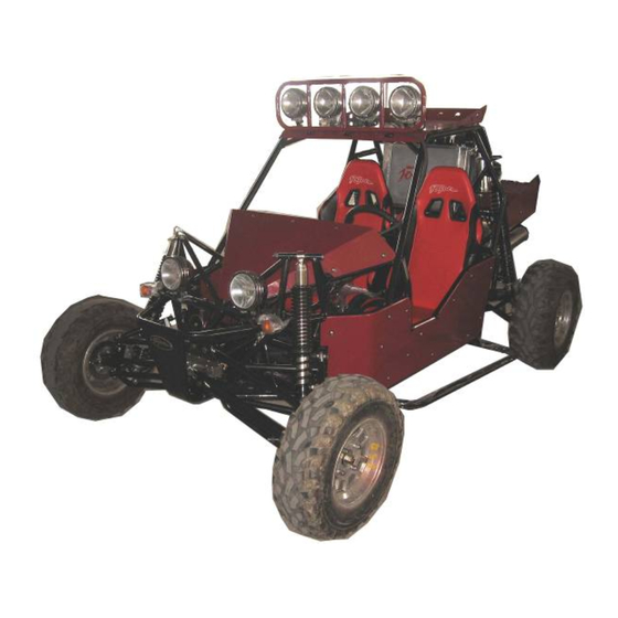
Owner’s Manual JNSZ800MVA Repair Manual Parts manual READ THIS MANUAL CAREFULLY. IT CONTAINS IMPORTANT SAFETY INFORMATION. MINIMUM RECOMMENDED OPERATOR AGE: FOR OFF-ROAD USE ONLY This vehicle is designed and manufactured for off-road use only. It does not confirm to federal motor vehicle safety standards, and operation on... - Page 2 Thank you for choosing JOYNER JNSZ800MVA. It represents the result of many years of JOYNER experience in the production of utility vehicles. With the purchase of this JOYNER, you can now appreciate the high degree of craftsmanship and reliability that have made JOYNER a leader in this field.
-
Page 3: Table Of Contents
CONTENTS Warranty policy ........................ 4 OWNER’S MANUAL ...................... 14 1.FOREWORD ......................14 2.A FEW WORDS ABOUT SAFETY ............... 15 3.IMPORTANT SAFETY INFORMATION ..............16 4.SAFETY LABELS ....................17 5.ARE YOU READY TO DRIVE? ................18 6.IS YOUR VEHICLE READY TO DRIVE? ............. 20 7.SAFE DRIVING PRECAUTIONS ................. -
Page 4: Warranty Policy
WARRANTY POLICY... -
Page 14: Owner's Manual
OWNER’S MANUAL 1.FOREWORD Thank you for choosing our Off highway recreational vehicle. We hope you will have fun with it. Before you drive the Off highway recreational vehicle, please read through this Owner’s Manual carefully as it contains important safety and maintenance information. Failure to follow the warnings contained in this manual can result in serious injuries. -
Page 15: A Few Words About Safety
2.A FEW WORDS ABOUT SAFETY In order to keep everyone safe, you must take responsibility for the safe operation of your Off highway recreational vehicle. To help you make informed decisions about safety, we have provided operating procedures and other information on labels and in this manual. This information alerts you to potential hazards that could hurt you or others. -
Page 16: Important Safety Information
3.IMPORTANT SAFETY INFORMATION Your Off highway recreational vehicle will provide you with many years of service and pleasure. Providing you take responsibility for your own safety and understand the challenges you can meet while driving. There is much that you can do to protect yourself when you drive. You’ll find many helpful recommendations throughout this manual. -
Page 17: Safety Labels
4.SAFETY LABELS This section presents some of the most important information and recommendations to help you drive your Off highway recreational vehicle safely. Spend a few moments to read these pages. The labels are considered permanent parts of the Off highway recreational vehicle. If a label comes off or becomes hard to read, contact your dealer for warning labels replacements. -
Page 18: Are You Ready To Drive
5.ARE YOU READY TO DRIVE? Before each drive, you need to make sure you and your Off highway recreational vehicle are both ready to drive. To help get you prepared, this section discusses how to evaluate your driving readiness, what items you should check on your Off highway recreational vehicle, and adjustments to make for your comfort, convenience, or safety. -
Page 19: Drive Training
Driving pants with knee and hip pads, a driving jersey with padded elbows, and a chest/shoulder protector. Drive Training Developing your driving skills is an on-going process. Even if you have derived other Off highway recreational vehicles, take time to become familiar with how this Off highway recreational vehicle works and handles. -
Page 20: Is Your Vehicle Ready To Drive
Operating this Off highway recreational vehicle after alcohol or drugs can seriously affect your judgment, cause you to react more slowly, affect your balance and perception, and could result in serious injury or death. Never consume alcohol or drugs before or while operating this Off highway recreational vehicle. -
Page 21: Safe Driving Precautions
Lights ■ Make sure the headlight; brake light and taillight are working properly. Throttle ■ Check the free play and adjust if needed. Press the throttle to make sure it moves smoothly without sticking, and snaps back automatically when it is released. Brakes ■... -
Page 22: Control Speed
Keep Hands and Feet on Controls Always keep both hands on the steering wheel and both feet on the foot controls. When driving your Off highway recreational vehicle. It is important to maintain your balance and to control of the Off highway recreational vehicle. - Page 23 recreational vehicle and other off-road vehicles. Always exercise caution and use extra care on rough, slippery and loose terrain. Failure to use extra care when operating on excessively rough, slippery or loose terrain could cause loss of traction or vehicle control, which could result in an accident, including an overturn.
-
Page 24: Specifications
8.SPECIFICATIONS DIMENSIONS Overall Length-------------------------------------------------------------------------------------------------------------113 in. (2880mm) Overall Width ----------------------------------------------------------------------------------------------------------------68in. (1740mm) Overall Height -------------------------------------------------------------------------------------------------------------- 67in. (1700mm) Wheelbase -------------------------------------------------------------------------------------------------------------------- 82 in. (2090mm) Front Track ---------------------------------------------------------------------------------------------------------------------- 58 in. (1475mm) Rear Track ----------------------------------------------------------------------------------------------------------------------58in.(1470mm) Ground Clearance -------------------------------------------------------------------------------------------------------- 12 1/2in. (320mm) ENGINE Type ---------------------------------------------------------------------------------------------------- 3-Bore, 4-Stroke, Liquid-cooled Bore x Stroke ------------------------------------------------------------------------------------------------------------- 72mm×66.5mm Displacement -------------------------------------------------------------------------------------------------------------------------- Corrected compression ratio -------------------------------------------------------------------------------------------------------- 9.5:1... -
Page 25: Operation Instruction
9.OPERATION INSTRUCTION WARNING-Do not attempts to start or operate the engine until completely familiar with the location and use of each control necessary to operate this vehicle. Operator must know how to stop this machine before starting and driving it. Control pedal Changes engine rpm and vehicle ground speed. - Page 26 • Pull up on shift selector collar and move lever to center position to place trans-axle in neutral. • Pull up on shift selector collar and move lever to position “R”, the vehicle will move backwards. Shift Selector Park brake lever FIGURE 2 FIGURE 3 Switch...
- Page 27 1200C/2480 F. Stop engine immediately. Check coolant lever and add if low, see authorized JOYNER dealer if temperature indicator stay on and overflow tank is full of coolant. (See figure 8) Indicates battery is charging. Check battery if voltmeter registers a charge that is Voltmeter: lower than normal.
- Page 28 FIGURE 9 Passengers The vehicle allows for two riders only. Make sure you brief your passenger on proper safety procedures like keeping hands, arms, feet and other bodily appendages inside the vehicle. Passengers should only be transported in factory-supplied seating. Operator and passenger are responsible for deciding if their situation warrants using Seat Belts.
-
Page 29: Maintenance
Chassis Maintenance Tire Maintenance Use only tires recommended by Joyner. It is important for your safety and the safety of others that the tires have correct air pressure. Check air pressure in four tires before each use. Visually inspect tires for loss of air throughout each day of operation. See Tire inflation Chart below for correct tire pressure. - Page 30 Parking Adjustment Pull the park brake lever up so that the unit can engage park brake. To release the unit, press button on front end of parking lever then push the parking lever to the bottom. Adjust the parking cable if necessary. (See figure 13) NUT #1 NUT #2 FIGURE 13...
-
Page 31: Front Wheel Replacement
Front Wheel Replacement Do not disassemble the center castle nuts when you replace the front wheels (See Fig. 15). Tighten the nuts after replacing the wheels. FIGURE 15 Rear Wheel Replacement Do not disassemble the center castle nuts when you replace the rear wheels (See Fig. -
Page 32: Shock Adjustment
.Shock adjustment 1. After a long time use, the shock need to be adjusted for more tension refer to maintenance and service log, adjust the shock with a special spanner. In other case, the chock nitrogen needs to be added to get more nitrogen pressure; the recommended nitrogen pressure is 1.0MPa/145psi. 2. -
Page 33: Clutch Replacement
Clutch replacement Remove two bolts, and demount Starter-assembly carefully. (See Fig. 17-20) Q1840845 Q1841245 FIGURE 17 FIGURE 18 S11-3708111 S11-3708110G FIGURE 20 FIGURE 19 Remove four bolts on the transmission case, lay down these carefully. When fix the four Caution: bolts in the transmission case;... - Page 34 FIGURE 23 FIGURE 24 Remove upper steel cushions and lower steel cushion. (See Fig. 25-26) 372-100203 S11-170010 FIGURE 25 FIGURE 26 .Insert a spine-shaft into the hole of the Clutch assy , remove the six bolts on the Clutch pressure plate, now It’s clear.
- Page 35 S11-1601020 S11-1601030 FIGURE 29 FIGURE 30 FIGURE 31 Insert a spline-shaft into the hole of the Clutch assy , fix the six bolts on the Clutch pressure plate , torque 28 N.M . (See Fig. 32-33) tighten them according to the prescribed FIGURE 32 FIGURE 33 Fix parts according to reverse operation to the disassembly.
-
Page 36: Front Wheel Alignment
Front Wheel Alignment Put the vehicle on level ground. The “tie-in” of the front wheels should be 0.63 inches. To check alignment, measure distance A and B between the centerline (CL) of the wheels. The proper toe-in dimension A should be 0.63 inches greater than dimension B. -
Page 37: Bulb Replacement
Engine relay Fuel pump relay Fan relay Spot light relay R gear indicator fuse Engine fuse Flash fuse Fuel pump fuse Gauge and indicator fuse ECU normal open circuits fuse Fan fuse Brake indicator fuse Bulb replacement To replace the bulb of the sport light, do the following, see Pic 1-Pic 6: Pic 1 Pic 2 Pic 3... - Page 38 Pic 4 Pic 5 Pic 6 4. Loose the 2 crews at the bottom of the head light, and take off the 2 hoops around the head light. 5. Separate the head light as the picture. 6. Unscrew the screw that fixes the bulb, and take off the bulb carefully. 7.
- Page 39 1.Drain fuel tank by allowing engine to run out of fuel, or use a fuel stabilizer. 2.Lubricate engine cylinder by removing the spark plug and pour one ounce of clean lubricating oil through the spark plug hole into the cylinder. Crank the engine slowly to spread oil and replace spark plug.
- Page 40 ENGINE WIRING DIAGRAM...
- Page 41 MAIN WIRING DIAGRAM...
- Page 42 Electrical schematic diagram IGN 2 Start motor Ignition switc h Spot light switch 1 I/p wiring conn 23 spot light*4 I/p wiring conn 21 Battery IGN 1 High beam R High beam switch 1 IGN 2 Fuelsensor High beam L oil pressure dipped beam R sensor...
-
Page 43: Engine Maintenance
Engine maintenance 1. Service Air Filter Service air filter every 80 hours NOTE: Service more often under dusty conditions. Cover Filter FIGURE 35 Remove filter cover (See Fig. 35). Check the filter cover and the air filter, if the filter cover and the air filter are dusty, please clear the filter cover and replace with a new air filter. - Page 44 With the engine warm, put the vehicle on the level ground. Shut down the engine, put a collecting oil plate under the engine oil outlet. Let the engine oil out fully (see Fig. 38). Tighten the engine oil outlet plug. Remove the oil filler cap (see Fig.
- Page 45 Reserve coolant tank FIGURE 40 FIGURE 5. Put the vehicle on level ground. Turn the coolant cap counterclockwise and open the cap (see Fig. 40). Pour fresh coolant to filler neck, Start the engine at idle.Increase the engine rev’s a few times.Repeat 2,3,4 till the coolant is at neck and no bubbles come up.Refit the coolant cap, turn it clockwise and tighten it.
-
Page 46: Spark Plug Inspection
Harm or damage may occur if using coolant does not meet the specification that is 50% standard green coolant and 50% distill water. 6. Idle Speed Adjustment Never make unnecessary adjustments. The factory recommended settings are correct for most applications. It’s not necessary to disassemble the screw unless the idle speed needs to adjustment. (See Fig. - Page 47 Spark plugs replacement The spark plugs should be replaced every 30000km/18641miles, or 18 months. Do the following step by step. Unscrew 8 screws and take off spark plug plastic cover. Clean the dust in the spark plug seat. Pull off the high-voltage wire,remove the spark plug with a special spanner. Insert a new spark plug or a cleaned spark plug, and turn a few rounds clockwise, if retardarce happen, take it off and try it again to make sure screw engaged correctly.
-
Page 48: Wedge Belt Figure
Wedge belt figure Correct installation and the proper tension will ensure electrical generator and air conditioner work well. If chap, tear, wear,or looseness happen, contact Joyner dealer and replace it immediately. Check the belt tension: Apply a pressure (about 100N/22.48lbf) on the belt, if the movement is more than 10mm/0.4inch, loosen the flange bolt and change the position of starter to tension the belt and fasten the bolt. - Page 49 ENGINE MECHANICAL SYSTEMS...
- Page 93 ELECTRIC INJECTION SYSTEM...
-
Page 135: Parts Manual
PARTS MANUAL 1.ENGINE 1.1 Cooling system ERP Code Part No. Part Description 02.DLJ.Q1400612 Q1400612 HEXAGON HEAD BOLT 02.DLJ.372-1307014 372-1307014 WATER PUMP PULLEY 02.DLJ.Q1840840 Q1840840 HEXAGON FLANGE BOLT 02.DLJ.Q1840855 Q1840855 BOLT(M8X55) 02.DLJ.Q1840865 Q1840865 HEXAGON FLANGE BOLT 02.DLJ.372-1307010 372-1307010 WATER PUMP SET 02.DLJ.372-1307015 372-1307015 ‘O’... -
Page 136: Cylinder Block
1.2 Cylinder block ERP Code Part No. Part Description 02.DLJ.372-1002010 372-1002010 CYLINDER BLOCK ASSY 02.DLJ.372-1002037 372-1002037 POSITION PIN 02.DLJ.372-1002046 372-1002046 CRANKCASE VENTILATION PIPE 02.DLJ.372-1002044 372-1002044 CYLINDER HEAD SEAL PLUG 02.DLJ.Q1840830 Q1840830 HEXAGON FLANGE BOLT 02.DLJ.372-1002060 372-1002060 KNOCK SENSOR 02.MV800.06.04.0001 MV800.06.04.00.01 POSITION PIN 02.DLJ.372-1002070 372-1002070... - Page 137 1.3 Crankshaft ERP Code Part No. Part Description 02.DLJ.372-1005031 372-1005031 PULLEY BOLT 02.DLJ.372-1005040 372-1005040 TORSION SHOCK ABSORBER ASSY 02.DLJ.372-1005018 372-1005018 CRANKSHAFT TIMING GEAR 02.DLJ.372-1005017 372-1005017 TOOTHED BELT BAFFLE 02.DLJ.372-1005015 372-1005015 CRANKSHAFT FRONT OIL SEAL 02.DLJ.372-1005033 372-1005033 NEEDLE BEARING 02.DLJ.372-1005032 372-1005032 WOODRUFF KEY 02.DLJ.372-1005010 372-1005010...
-
Page 138: Exhaust Manifold
1.4 Exhaust manifold ERP Code Part No. Part Description 02.DLJ.372-1008033 372-1008033 EXHAUST MANIFOLD WASHER 02.DLJ372-100801BA 372-100801BA EXHAUST MANIFOLD 02.DLJ.Q1200825F3 Q1200825F3 STUD 02.DLJ.Q33008 Q33008 HEXAGON NUT 02.DLJ.372-1008044 372-1008044 HEAT INSULATOR 02.DLJ.Q1460612 Q1460612 HEXAGON HEAD BOLT 02.DLJ.S11-1205110 S11-1205110 OXYGEN SENSOR 02.DLJ.Q1200835F3 Q1200835F3 STUD 02.DLJ.S11-3724863 S11-3724863... -
Page 139: Intake System
1.5 Intake system ERP Code Part No. Part Description 02.DLJ.Q1420625 Q1420625 HEXAGON HEAD BOLT 02.DLJ.372-1107011CA 372-1107011CA BODY–THROTTLE 02.DLJ.372-1107012 372-1107012 THROTTLE BODY WASHER 02.DLJ.Q1840620 Q1840620 HEXAGON FLANGE BOLT 02.DLJ.372-1008043 372-1008043 ACCELERATOR PULLING WIRE BRACKET 02.DLJ.S11-1109411 S11-1109411 INTAKE TEMPERATURE AND PRESSURE SENSOR 02.DLJ.Q1400416 Q1400416 HEXAGON HEAD BOLT... -
Page 140: Lubricating Device
1.6 Lubricating device ERP Code Part No. Part Description 02.DLJ.372-1012010 372-1012010 OIL FILTER 02.DLJ.372-1009130 372-1009130 OIL DIP STICK 02.DLJ.372-1009120 372-1009120 OIL DIP STICK PIPE 02.DLJ.372-1011055 372-1011055 SEAL STRIP 02.DLJ.372-1011021 372-1011021 OIL PUMP GASKET 02.DLJ.372-1011030 372-1011030 OIL PUMP ASSY 02.DLJ.Q1840825 Q1840825 BOLT 02.DLJ.Q1840855 Q1840855... -
Page 141: Cylinder Head
1.7 Cylinder head ERP Code Part No. Part Description 02.DLJ.372-1003074 372-1003074 SPARK PLUG SLEEVE 02.DLJ.Q1400638 Q1400638 HEXAGON HEAD BOLT 02.DLJ.372-1003051 372-1003051 CYLINDER HEAD BOLT 02.DLJ.372-1003052 372-1003052 CYLINDER HEAD BOLT WASHER 02.DLJ.S11-3808013 S11-3808013 WATER TEMP SENSOR 02.DLJ.S11-1003069 S11-1003069 CAMSHAFT POSITION SENSOR 02.DLJ.Q1400816 Q1400816 HEXAGON HEAD BOLT... - Page 142 1.8 Cover-valve chamber ERP Code Part No. Part Description 02.DLJ.372-1003090 372-1003090 OIL CAP 02.DLJ.Q2540616 Q2540616 SCREW 02.DLJ.372-1003075 372-1003075 ENGINE TRIMING COVER ASSY 02.DLJ.372-1003030 372-1003030 ROCKER COVER ASSY 02.DLJ.372-1003036 372-1003036 CYLINDER HEAD COVER GASKET 02.DLJ.Q1460625 Q1460625 HEXAGON HEAD BOLT...
- Page 143 1.9 Oil pan ERP Code Part No. Part Description 02.DLJ.372-1009010 372-1009010 OIL PAN ASSY 02.DLJ.Q1420612 Q1420612 HEXAGON HEAD BOLT 02.DLJ.372-1009017 372-1009017 OIL PLUG WASHER 02.DLJ.372-1009014 372-1009014 DRAIN PLUG...
-
Page 144: Valve Mechanism
1.10 Valve mechanism ERP Code Part No. Part Description 02.DLJ.372-1007030 372-1007030 TENSIONING PULLEY 02.DLJ.Q1401045 Q1401045 HEXAGON HEAD BOLT 02.DLJ.Q1400616 Q1400616 HEXAGON HEAD BOLT 02.DLJ.372-1007040 372-1007040 TIMING GEAR COVER 02.DLJ.Q1460625 Q1460625 HEXAGON HEAD BOLT 02.DLJ.Q1460650 Q1460650 HEXAGON HEAD BOLT 02.DLJ.Q43140 Q43140 SHIELD-SHAFT SPRING RING 02.DLJ.372-1006032 372-1006032... - Page 145 1.10 Valve mechanism ERP Code Part No. Part Description 02.DLJ.372-1006060 372-1006060 EXHAUST CAMSHAFT ASSY 02.DLJ.372-1007017 372-1007017 ADJUSTMENT WASHER 02.DLJ.372-1007018 372-1007018 VALVE LIFTER 02.DLJ.372-1007019 372-1007019 VALVE LOCK BLOCK 02.DLJ.372-1007021 372-1007021 EDDY SLEEVE 02.DLJ.372-1007014BA 372-1007014BA UPPER VALVE SPRING SEAT 02.DLJ.372-1007013 372-1007013 VALVE SPRING 02.DLJ.372-1007020 372-1007020 VALVE SEAL...
-
Page 146: Ignition Device
1.11 Ignition device ERP Code Part No. Part Description 02.DLJ.S11-3705110JA S11-3705110JA IGNITION COIL 02.DLJ.Q2320525 Q2320525 SCREW AND WASHER UNIT 02.DLJ.S11-3705001 S11-3705001 IGNITION COIL BRACKET 02.DLJ.S11-3707100 S11-3707100 SPARK PLUG ASSY 02.DLJ.Q1460820 Q1460820 HEXAGON HEAD BOLT 02.DLJ.S11-3707040 S11-3707040 HI.TENSION CORD NO.3 02.DLJ.S11-3707030 S11-3707030 HI.TENSION CORD NO.2 02.S800.04.01.05... -
Page 147: Piston And Connecting Rod Device
1.12 Piston and connecting rod device ERP Code Part No. Part Description 02.DLJ.372-1DE1004030 372-1DE1004030 PISTON RING ASSY 02.DLJ.372-1004031 372-1004031 PISTON PIN 02.DLJ.372-1004021 372-1004021 PISTON 02.DLJ.372-1004110 372-1004110 CONNECTING ROD ASSY 02.DLJ.372-1DF1004110 372-1DF1004110 CONNECTING ROD BEARING... - Page 148 1.13 Other accessory 1 ERP Code Part No. Part Description 02.DLJ.S11-3724180CA S11-3724180CA Engine Harness 02.DLJ. S11-BJ3605010TA S11-BJ3605010TA renovated ECU 02. SV1100.05.02.01 SV1100.05.02.01.00 Shifter Bracket 02.DLJ.S11-1206211 S11-1206211 carbon can PCV 02.DLJ.S11-3708110BA S11-3708110BA Starter 02.DLJ.S11-1700103 S11-1700103 lower Steel cushion 02.DLJ.S11-1200011CA S11-1200011CA Single Exhaust Gasket 02.DLJ.Q1841245 Q1841245 Hex socket head bolt M12x45...
- Page 149 1.14 Other accessory 2 ERP Code Part No. Part Description 02.DLJ.S11-3701110BB S11-3701110BB Alternator 02.DLJ.S11-3701211BA S11-3701211BA Alternator bracket 02.DLJ.S11-1001415BA S11-1001415BA Rear bracket 02.DLJ.S11-3701315 S11-3701315 V-ribbed belt...
-
Page 150: T08A2 Transsmission Illustration
2. 4T08A2 TRANSSMISSION ILLUSTRATION 1.CASE&ACCESSORY ERP CODE Code name Description 02.DLJ.QR512-1701101 QR512-1701101 CASE.CLUTCH 02.DLJ.4T08A1-1701111 4T08A1-1701111 CASE.TRANSMISSION 02.DLJ.5T07-1701020 5T07-1701020 SIDE COVER 02.DLJ.5T07-1702010 5T07-1702010 DECLUTCH BEARING 02.DLJ.5T07-1702020A 5T07-1702020A DECLUTCH FORK 02.DLJ.5T07-1702004 5T07-1702004 SLEEVE.CLUTCH FORK 2 02.DLJ.5T07-1702030 5T07-1702030 SEAL.CLUTCH FORK 02.DLJ.5T07-1702001 5T07-1702001 SLEEVE.CLUTCH FORK 1 02.DLJ.QR512-1701103 QR512-1701103 DOUBLE-SCREW ROD... - Page 151 1.CASE&ACCESSORY ERP CODE Code name Description 02.DLJ.5T07-3729010 5T07-3729010 SWITCH.BACK-UP LIGHT 02.DLJ.5T07-1701058A 5T07-1701058A DOUBLE-SCREW ROD 02.DLJ.5T07-1701009 5T07-1701009 STOP PLATE.BEARING 02.DLJ.5T07-1701004 5T07-1701004 OIL-STOP PLATE 02.DLJ.GB/T5789-1986 GB/T5789-1986 AM6×12/BOLT AM6X12 02.DLJ.GB/T7246-1987 GB/T7246-1987 6/WASHER 6 02.DLJ.5T07-1701400 5T07-1701400 OIL GROOVE ASSY 02.DLJ.5T07-1702080A 5T07-1702080A ROCKER.CLUTCH 02.DLJ.GB/T5789-1986 GB/T5789-1986 AM8×35/BOLT AM8X35 02.DLJ.GB/T6177-2000 GB/T6177-2000...
- Page 152 2.COUNTERSHAFT ERP CODE Code name Description 02.DLJ.4T08A-1701401 4T08A-1701401 COUNTERSHAFT 02.DLJ.QR512-1701410 QR512-1701410 DRIVEN GEAR ASSY.FIRST GEAR 02.DLJ.4T08A1-1701420 4T08A1-1701420 DRIVEN GEAR ASSY.SECOND GEAR 02.DLJ.4T08A1-1701441 4T08A1-1701441 DRIVEN GEAR.THIRD GEAR 02.DLJ.4T08A1-1701461 4T08A1-1701461 DRIVEN GEAR.FOURTH GEAR 02.DLJ.5T07-1701610 5T07-1701610 BEARING.OUTPUT SHAFT.FRONT 5T07-1701240 02.DLJ.5T07-1701240 NEEDLE BEARING.1ST GEAR&2ND GEAR OUTER RING.SYNCHRONIZER.1ST 02.DLJ.QR512-1701439...
- Page 153 2.COUNTERSHAFT ERP CODE Code name Description Quantity SPRING.SYNCHRONIZER.1ST 02.DLJ.QR512-1701433 QR512-1701433 GEAR&2ND GEAR GEAR-HUB.SYNCHRONIZER.1ST 02.DLJ.QR512-1701434 QR512-1701434 GEAR&2ND GEAR GEAR-SLEEVE.SYNCHRONIZER.1ST 02.DLJ.QR512-1701431 QR512-1701431 GEAR&2ND GEAR GUIDE BLOCK.SYNCHRONIZER.1ST 02.DLJ.QR512-1701432 QR512-1701432 GEAR&2ND GEAR RETAINER.SYNCHRONIZER.1ST 02.DLJ.5T07-1701205 5T07-1701205 GEAR&2ND GEAR 02.DLJ.5T07-1701202 5T07-1701202 SPACER.3RD GEAR&4TH GEAR 02.DLJ.5T07-1701250 5T07-1701250 REAR BEARING.OUTPUT SHAFT ADJUSTING WASHER.
-
Page 154: Input Shaft Assy
3.INPUT SHAFT ASSY Description No ERP CODE Code name 02.DLJ.4T08A1-1701201 4T08A1-1701201 INPUT SHAFT 02.DLJ.5T07-1701080 5T07-1701080 SEAL.INPUT SHAFT 02.DLJ.4T08-1701130 4T08-1701130 BEARING 6204/YA/P63 02.DLJ.4T08A1-1701240 4T08A1-1701240 DRIVE GEAR ASSY.3RD GEAR 02.DLJ.5T07-1701150 5T07-1701150 NEEDLE BEARING.3RD GEAR&4TH GEAR RING.SYNCHRONIZER.3RD GEAR&4TH 02.DLJ.QR512-1701257 QR512-1701257 GEAR&5TH GEAR SYNCHRONIZER ASSY.3RD GEAR&4TH 02.DLJ.QR512-1701250 QR512-1701250 GEAR... - Page 155 3.INPUT SHAFT ASSY Description No ERP CODE Code name WAVEFORM WASHER 02.DLJ.QR512-1701258 QR512-1701258 RING.SYNCHRONIZER 02.DLJ.4T08A1-1701260 4T08A1-1701260 DRIVING GEAR ASSY.4TH GEAR 02.DLJ.5T07-1701110 5T07-1701110 BACK BEARING/INPUT SHAFT 02.DLJ.QR512-1701287 ADJUSTING WASHER. BACK QR512-1701287 BEARING/INPUT SHAFT 02.DLJ.4T08A-1701202 4T08A-1701202 SLEEVE.INPUT SHAFT 02.DLJ.4T08A1-1701200 4T08A1-1701200 INPUT SHAFT ASSY 02.DLJ.QR512-1701298 QR512-1701298 NUT.SYNCHRONIZER.5TH GEAR...
- Page 156 4.SHIFT FORK& SHIFT- FORK SHAFT Description No ERP CODE Code name 02.DLJ.QR512-1702311 QR512-1702311 SHIFT FORK.1ST GEAR&2ND GEAR 02.DLJ.5T07-1702041A 5T07-1702041A SHIFT FORK.3RD GEAR&4TH GEAR 02.DLJ.GB/T308-2002 GB/T308-2002 STELL BALL 7.9375 02.DLJ.5T07-1702042A 5T07-1702042A SHIFT FORK.5TH GEAR 02.DLJ.5T07-1702061A 5T07-1702061A SHIFT FORK.3RD GEAR&4TH GEAR 02.DLJ.4T08A-1702001 4T08A-1702001 STOP BLOCK 02.DLJ.QR512-1702231...
- Page 157 4.SHIFT FORK& SHIFT- FORK SHAFT Description No ERP CODE Code name 02.DLJ.QR512-1701421 QR512-1701421 SHIFT SHAFT.3RD GEAR&4TH GEAR 02.DLJ.QR512-1702431 QR512-1702431 SHAFT. SHIFT FORK.5TH GEAR 02.DLJ.QR512-1702441 QR512-1702441 SHAFT. SHIFT FORK.REVERSE GEAR 02.DLJ.5T07-1702234 5T07-1702234 SCREW PLUG.SHIFT-FORK SHAFT WASHER. SCREW PLUG.SHIFT-FORK 02.DLJ.5T07-1702233 5T07-1702233 SHAFT 02.DLJ.QR512-1702341 QR512-1702341 SHIFT-FORK PIN.REVERSE GEAR...
- Page 158 5.SHIFT CONTROL MACHANISM Description No ERP CODE Code name 02.DLJ.5T07-1702100A 5T07-1702100A SHIFT-SELECT SHAFT ASSY 02.DLJ.5T07-1702101A 5T07-1702101A SHIFT-SELECTING SHAFT SNAP RING.STOP PLATE.SHIFT 02.DLJ.QR512-1702214 QR512-1702214 INTERLOCK 5T07-1702102 RELEASE-SPRING SEAT.1ST GEAR&2ND 02.DLJ.5T07-1702102 GEAR 5T07-1702103 02.DLJ.5T07-1702103 RELEASE-SPRING.1ST GEAR&2ND GEAR 02.DLJ.5T07-1702104 5T07-1702104 SPRING-STOP PLATE 02.DLJ.5T07-1702107A 5T07-1702107A STOP PLATE.SHIFT INTERLOCK 02.DLJ.5T07-1702105A...
- Page 159 5.SHIFT CONTROL MACHANISM Description No ERP CODE Code name 02.DLJ.5T07-1702109A 5T07-1702109A LIMITING SPRING.REVERSE GEAR 02.DLJ.QR512-1702111A QR512-1702111A LIMITING CAM.REVERSE GEAR 02.DLJ.GB/T879,1-2000 GB/T879.1-2000 PIN 5X22 GUIDE CASE ASSY. SHIFT-SELECT 02.DLJ.5T07-1702070A 5T07-1702070A SHAFT 02.DLJ.5T07-1702071A 5T07-1702071A GUIDE CASE. SHIFT-SELECT SHAFT STOP PLATE.RELEASE 02.DLJ.5T07-1702072 5T07-1702072 SPRING.5TH@REVERSE 02.DLJ.GB/T5789-1986 GB/T5789-1986...
- Page 160 5.SHIFT CONTROL MACHANISM No ERP CODE Code name Description WASHER.STOP SCREW.REVERSE 02.DLJ.QR512-1702229 QR512-1702229 GEAR 02.DLJ.GB/T5789-1986 GB/T5789-1986 BOLT AM 8X80 02.DLJ.5T07-1702063 5T07-1702063 PUSHING BLOCK.SHIFT ANTI-DUST COVER.SHIFT-SELECT 02.DLJ.5T07-1702062 5T07-1702062 SHAFT 03.02.6170-M8/05 6170-M8 NUT M8 03.05. 93-Φ8/05 93-Φ8 Spring washer 8 02.DLJ.5T07-1702046 5T07-1702046 BIG WASHER.SHIFT ARM 02.DLJ.5T07-1702045 5T07-1702045...
- Page 161 6.DRIVEN GEAR ASSY.SPEED REDUCER Description No ERP CODE Code name 02.DLJ.4T08A2-1701308 4T08A2-1701308 Differential case 02.DLJ.4T08A-1701604 4T08A-1701604 DRIVEN GEAR.SPEED REDUCER 02.DLJ.5T07-1701010 5T07-1701010 Differential seal assy (left) 02.DLJ.5T07-1701310 5T07-1701310 FRONT BEARING 6007 02.DLJ.QR512-1701604 QR512-1701604 DRIVING GEAR.ODOMETER 02.DLJ.GB/T879,1-2000 GB/T879.1-2000 Needle bearing D5×36 02.DLJ.5T07-1701090 5T07-1701090 Differential seal assy (right) 02.DLJ.5T07-1701309...
- Page 162 6.DRIVEN GEAR ASSY.SPEED REDUCER 02.DLJ.5T07-1701306 5T07-1701306 Half axle adjusting washer 02.DLJ.5T07-1701320 5T07-1701320 REAR BEARING 6207 02.DLJ.5T12H-1709506 5T12H-1709506 limited-thrust ring 02.DLJ.4T08A2-1701611 4T08A2-1701611 output shaft 02.DLJ.MQC4-2303016 MQC4-2303016 RETAINER RING 02.DLJ.4T08A2-1701600 4T08A2-1701600 Differential assy...
-
Page 163: Chassis
3.CHASSIS 1.Frame,aluminium board frame ,aluminium board ERP Code Code name Description Q'ty 02. MVA800.01.01 MVA800.01.01.00.00 Frame component 02. MVA800.01.02.0021 MVA800.01.02.00.21 front motherboard 02. MVA800.01.02.0022 MVA800.01.02.00.22 pedal board 02. MVA800.01.02.0023 MVA800.01.02.00.23 seat board 02. MVA800.01.02.0024 MVA800.01.02.00.24 engine board... - Page 164 02. MVA800.01.02.0025 MVA800.01.02.00.25 left side board 02. MVA800.01.02.0026 MVA800.01.02.00.26 right side board 03.01.D818-M6X16 D818-M6X16 Cross head screw M6X16 02.JD.0900008 JD0900008 Washer 6 03.02.6183,1-M6/05 6183,1-M6 Self-locking nut M6 03.01.D818-M6X16 D818-M6X16 Cross head screw M6X16 02.JD.0900008 02.JD.0900008 Washer 6 03.02.6183,1-M6/05 6183,1-M6 Self-locking nut M6 03.01.D818-M6X16 D818-M6X16 Cross head screw M6X16...
-
Page 165: Engine Mount Assy
2.Engine mount assy Engine mount assy ERP Code Code name Description Q'ty 02.SV800.04.01.02 SV800.04.01.02.00 front engine mount 03.03.95-Φ10X20X2/05 95-Φ10X20X2 asherΦ10X20X2 03.05.93-Φ10/05 93-Φ10 spring asher Φ10 03.01.5787-M10X30/05 5787-M10X1.5X30 bolt-asher M10X1.5X30 02.D650.04.01.0001 D650.04.01.00.01 engine rubber bumper 03.02.2842-M10X1.25/05 2842-M10X1.25 nut-asher M10x1.25 02.DLJ.372-0000E01AA 372-0000E01AA engine(372) 02.MV800.04.01.03 MV800.04.01.03.00... - Page 166 02.DLJ.4T08A2-1700010 4T08A2-1700010 4T08A2 transmmision 3.Gear-shift mechanism Gear-shift mechanism ERP Code Code name Description Q'ty 03.01.5787-M6X12/05 5787-M6X12 M6X12 bolt 02.SV800.05.02.0001A SV800.05.02.00.01A plastic cover 02.S650.05.02.01 S650.05.02.01.00 shifter control assembly 02.S650.05.02.01.01 S650.05.02.01.01 rubber shifter indication 02.S650.05.02.01.02 S650.05.02.01.02 rubber shifter cover 02.S650.05.02.01.03 S650.05.02.01.03 control framework 02.SV800.05.02.0005 SV800.05.02.00.05 orientation metal sheet...
- Page 167 02.MV800.05.02.02 MV800.05.02.02.00 shifter soft shaft 1 03.01.5787-M6X25/05 5787-M6X25 M6x25 bolt...
- Page 168 4.Steering assy Steering assy 13 14 29 30 3132 33 34 35 23 24 25 42 41 20 21 No. ERP Code Code name Description Q'ty 03.01.70,2-M6X20 70.2-M6X20 M6X20 screw 02.TR1100.05.01.0002-3 TR1100.05.01.00.02-3 plastic cover 02.TR1100.05.01.0002 TR1100.05.01.00.02 350steering wheel 03.02.6183,1-M6/05 6183.1-M6 M6 self-locking nut 02.TR1100.05.01 TR1100.05.01.00.00...
- Page 169 02.D800.05.01.01.02 D800.05.01.01.02 steering column housing 02.276-B61803 276-B61803 61803 bearing 03.09.893,22-Φ28 893.2-Φ28 circlip Φ28, internal 03.09.894,1-Φ15 894.1-Φ15 Φ15, external circlip 02. D650.05.01.01 D650.05.01.01.00 steering column assy 03.02.2842-M10X1,25/05 2842-M10X1.25 M10X1.25 nut 03.01.5787-M10X1,25X25/05 5787-M10X1.25X25 M10X1.25X25 bolt 03.03.95-Φ8X24X2/05 96-Φ8X24X2 Φ8 washer(8.4X24X2) 03.05.93-Φ8 93-Φ8 Φ8 spring shim 03.01.5782-M8X25/05 5782-M8X25 M8X25 bolt...
- Page 170 5.Throttle and park assy Throttle and park assy 16 17 Code name Code name Description Q'ty 03.01.5787-M8X20/05 5787-M8X20 Bolt-washer M8X20 02.MV800.07.01.01 MV800.07.01.01.00 four caliper hydraulic brake assy 03.01.5787-M6X20/05 5787-M6X20 Bolt-washer M6X20 02.D1600.01.02.0008 D1600.01.02.00.08 support 03.02.2842-M6/05 2842-M6 nut M6 03.01.5787-M6X20/05 5787-M6X20 Bolt-washer M6X20 03.02.2842-M6/05 2842-M6...
- Page 171 02.D650.07.01.0004A D650.07.01.00.04A pushing bar 03.02.6172,1-M8/05 6172.1-M8 nut M8 02.D650.07.01.00.03 D650.07.01.00.03 push rod holder 03.08.91-φ3,2X30/05 91-φ3,2X30 cotter pin 3.2X30 03.03.95-Φ10X28X2/05 95-Φ10X28X2 washer(Φ10.5XΦ18XΦ1.6) 02.SV1100.07.04.02 SV1100.07.04.02.00 clutch pedal 02.D650.07.01.0005 D650.07.01.00.05 pedal rubber cover 02.SV800.07.04.01 SV800.07.04.01.00 cable, clutch 03.01.70,1-M6X55/05 70.1-M6X55 M6X55 socket head bolt 03.02.6172,1-M6/05 6172.1-M6 M6 nut(m=5.2)
- Page 172 6.Brake assy brake assy To front right wheel To rear right wheel To front left wheel To rear left wheel No. Erp code Code name Description Q'ty 02.SV800.07.01.01.01 SV800.07.01.01.01 disc brake with floating caliper,front 02.SV800.07.01.01.02 SV800.07.01.01.02 disc brake with floating caliper,rear 02.DN250.04.01.01 DN250.04.01.01.00 Master cylinder assy...
- Page 173 02.D650.07.01.0004A D650.07.01.00.04A Master cylinder rod 02.MV800.07.01.01 MV800.07.01.01.00 four caliper hydraulic brake assy 7.Parking brake assy parking brake assy No. Erp code Code name Description Q'ty 02.SV800.07.01.01.01 SV800.07.01.01.01 disc brake with floating caliper,front 02.D650.07.02.03.02 D650.07.02.03.02 single hydraulic oil cup 02.D650.07.02.03.03 D650.07.02.03.03 single hydraulic pump 02.D650.07.02.03.04 D650.07.02.03.04...
- Page 174 8.Front susp assy Front susp assy 15 17 17 15 13 11 34 35 36 33 34 35 36 14 12 ERP Code Code name Description Q'ty 02.S650.03.01.0002 S650.03.01.00.02 M12X1.5 wheel nut 02.JD.0360010 JD0360010 rubber dirt-proof boot 02.S650.03.01.01A S650.03.01.01.00A left wheel(27X8-12) 03.08.91-φ4X40/05 91-φ4X40 cotter pin φ4X40...
- Page 175 02.D650.03.02.0005 D650.03.02.00.05 brake disk 02.D650.03.02.0008 D650.03.02.00.08 M6 bolt 02.D800.03.01.0005 D800.03.01.00.05 30X62X16 ball bearing 02.D800.03.01.0009 D800.03.01.00.09 40x62x7 grease seal 03.01.5782-M16X85/05 5782-M16X85 M16X85 bolt 02.D800.02.01.0002 D800.02.01.00.02 bushing 02. N650.02.01.02 N650.02.01.02.00 upper suspension arm,left 02.D800.02.01.0001 D800.02.01.00.01 radial bearing 03.09.893,2-φ42 893.2-42 circlip φ42 02.D800.02.01.0002 D800.02.01.00.02 bushing 03.02.6185,1-M16/05...
-
Page 176: Fuel Tank And Gasoline Pump
9.Fuel tank and gasoline pump Fuel tank and gasoline pump No. ERP Code Code name Description Q'ty 02.MV800.04.03.01 MV800.04.03.01.00 fuel tank 02.SR2000.04.03.0003A SR2000.04.03.00.03A fuel tank cap 02. MVA800.04.03.03 MVA800.04.03.03.00 fuel level sensor 02.SR2000.04.03.03.01 SR2000.04.03.03.01 rubber washer 02.D650.04.03.0004 D650.04.03.00.04 hoop (10-16) 0.3meter 02.FTCARB-0816 FTCARB-0816... - Page 177 M6X30 cross groove head 03.01.D818-M6X30 818-M6X30 screw 03.03.95-φ6X13X1,5/05 95-φ6X13X1,5 washer φ6X13X1,5 03.05.93-Φ6/05 93-Φ6 spring washer Ф6 03.02.41-M6/05 41-M6 hex nut M6 M6X50 cross groove head 03.01.D818-M6X50 818-M6X50 screw 02.D1600.04.03.02 D1600.04.03.02.00 fuel pump 0.2meter 02. FTCARB-0816 FTCARB-0816 fuel hose(φ8xφ16) 02.D1600.04.03.03 D1600.04.03.03.00 fuel press adjuster 03.01.5782-M4X40/05 5782-M4X40...
- Page 178 10.Muffler MUFFLER No. ERP Code Code name Description Q'ty 02.DLJ.472-1008033 472-1008033 exhaust manifold gasket 02.SV1100.04.04.03 SV1100.04.04.03.00 exhaust manifold 02.DLJ.S11-1205110JA S11-1205110JA oxygen sensor 02.SV1100.04.04.04 SV1100.04.04.04.00 seal washer 03.01.5787- M8X35/05 5787- M8X35 nut-washer 02.SV1100.04.04.02A SV1100.04.04.02.00A catalac convertor 02. C1100.01.02.0005 C1100.01.02.00.05 guide board 1 for cooling 03.02.6183,1-M8/05 6183,1-M8 self-locking nut M8...
- Page 179 02.SV800.01.02.0003 SV800.01.02.00.03 muffler bracket 03.01.5787-M8X25/05 5787-M8X25 bolt-washer M8*25 03.02.6183,1-M8/05 6183,1-M8 M8 self-locking nut 03.03.95-Φ8X24X2 95-Φ8X24X2 washer Φ8X24X2 02.SV800.01.02.0006 SV800.01.02.00.06 wire clamp...
- Page 180 11.Rear susp left Rear susp,left 27 29 No. ERP Code Code name Description Q'ty 02.S650.03.01.0002 S650.03.01.00.02 wheel nut M12X1.5 02.S650.03.02.01A S650.03.02.01.00A wheel(27X11-12),BL 03.08.91-φ4X40/05 91-φ4X40 cotter pin 4X40 02.DLJ.JGC2202-K JGC2202-K slotted nut M22X1.5,rear shaft 02.D650.03.02.0004A D650.03.02.00.04A disk base 02.D650.03.02.0003A D650.03.02.00.03A M12X1.5 bolt 02.D650.03.02.0005 D650.03.02.00.05 brake disk...
- Page 181 02.DLJ.SH07680 SH07680 BIG band 02.DLJ.BT-1085 BT-1085 inner boot seal 02.DLJ.SH07350 SH07350 SMALL band 02.DLJ.PT SZW5008 PT SZW5008 end motion type inboard joint 02.DLJ. PT SZ-9037 PT SZ-9037 solid bar,left 02.DLJ.PT SZW1003 PT SZW1003 fixed enter type outboard joint 02.MV800.03.02.01.00 MV800.03.02.01.00 left drive shaft 03.02.5782-M15X1.5X80/05 5782-M15X1.5X80X30...
- Page 182 12.Rear susp,right Rear susp,right 30 31 32 33 32 31 34 No. ERP Code Code name Description Q'ty 02. S650.03.01.0002 S650.03.01.00.02 wheel nut M12X1.5 02.S650.03.02.04A S650.03.02.04.00A wheel(27X11-12),BR (F938) 03.08.91-φ4X40/05 91-φ4X40 cotter pin 4X40 02.DLJ.JGC2202-K JGC2202-K slotted nut M22X1.5,rear shaft 02.D650.03.02.0004A D650.03.02.00.04A disk base 02.D650.03.02.0003A...
- Page 183 02.DLJ.SH07680 SH07680 big band 02.DLJ.PT SZW1003 PT SZW1003 fixed enter type outboard joint 02.DLJ. PT SZ-9015 PT SZ-9015 solid bar,right 02.DLJ.PT SZW5008 PT SZW5008 end motion type inboard joint 02.DLJ.2303016 2303016 steel cable baffle ring 02. N650.03.02.02 N650.03.02.02.00 right drive shaft 03.01.5782-M15X1.5X80/05 5782-M15X1.5X80 M15X1.5X80 bolt...
- Page 184 13.Cooling cycle cooling cycle 38 39 38 39 37 38 39 ERP Code Code name Description Q'ty 03.01.D818-M6*16 818-M6X16 Cross head screw M6*16 02.D650.04.07.0003 D650.04.07.00.03 cover, oil separator 02.D650.04.07.0002 D650.04.07.00.02 air filter, oil separator 02.SV800.04.07.0001 SV800.04.07.00.01 hoop(21-38) 02. D650.04.07.0001 D650.04.07.00.01 oil separator 03.01.5787-M8X20/05 5787-M8X20...
- Page 185 02. SV1100.04.02.0002 SV1100.04.02.00.02 small cooling cycle hose 02.D1600.04.02.0006 D1600.04.02.00.06 hoop(16-25) 02.D650.04.02.0003 D650.04.02.00.03 hoop(25-38),water tube 02.D650.04.02.0003 D650.04.02.00.03 hoop(25-38),water tube 02. D650.04.02.0001 D650.04.02.00.01 water outlet hose 1, engine 02. MV800.04.02.01 MV800.04.02.01.00 radiator support 03.02.6183,1-M8/05 6183,1-M8 self-locking nut M8 02.D800.04.02.02 D800.04.02.02.00 reserve tank 02.D800.04.02.0003 D800.04.02.00.03 reserve tank body...
- Page 186 14.Electical appliance Electrical appliance ERP Code Code name Description Q'ty 02.D1600.06.11A D1600.06.11.00.00A headlight 02.D1600.06.11.0001 D1600.06.11.00.01 headlight bulb 02.D650.06.00.05 D650.06.00.05.00 front turning light,left 02.D650.06.00.15 D650.06.00.15.00 front turning light,right...
- Page 187 02.D650.06.00.09 D650.06.00.09.00 horn 02.D25007914A D25007914A flasher apparatus 02.D25007924 D25007924 flasher coat 02.JD.0460003 JD0460003 washer 02.DS250.10.000005 DS250.10.00.00.05 horn button 02.D1600.06.03A D1600.06.03.00.00A switch assy 02.MV800.06.02 MV800.06.02.00.00 speedometer 02.D1600.06.05 D1600.06.05.00.00 tachometer 02.MV800.06.03 MV800.06.03.00.00 Coolant temperature indicator 02.D1600.06.09 D1600.06.09.00.00 voltmeter 02. N650.06.04 N650.06.04.00.00 fuel level gauge 02.D1600.06.07 D1600.06.07.00.00 oil pressure gauge...
- Page 188 15.Fin assy,front cover fin assy,front cover 1 2 3 No. ERP Code Code name Description Q'ty 03.01.D818-M6X16 818-M6X16 Cross head screw M6X16 02.JD0900008 JD0900008 Washer 6 03.02.6183,1-M6/05 6183.1-M6 Self-locking nut M6 02. MVA800.01.02.0005 MVA800.01.02.00.05 front cover plate 02. MVA800.01.02.0007 MVA800.01.02.00.07 right side fin 02.
- Page 189 12618-4X10 03.10.12618-4X10 rivet 4X10 03.10.12618-4X10 12618-4X10 rivet 4X10 02. MVA800.01.02.0028 MVA800.01.02.00.28 fin assy 16.Seat and safety belt seat and safety belt No. ERP Code Code name Description Q'ty 02.D650.08.01.0001A D650.08.01.00.01A safty belt 02.D650.08.01.0013 D650.08.01.00.13 safty belt tube...
- Page 190 02.D650.08.01.03 D650.08.01.03.00 seat , left 02.D650.08.01.04 D650.08.01.04.00 seat , right 02.D650.08.01.03.01 D650.08.01.03.01 Track without release lever 02.D650.08.01.03.02 D650.08.01.03.02 Track with release lever 17. Rack relative option rack No. ERP Code Code name Description Q'ty 02.MVA800.99990110 MVA800.99.99.01.10 aluminium roof rack 03.01.5787-M10X35 /05 5787-M10X35 bolt-washer M10X35 02.D1600.01.02.0007...
- Page 191 18.Fender relative option FENDER OPTION No. ERP Code Code name Description Q'ty 02.C650.08.01.13 C650.08.01.13.00 fender 02. C800.02.01.02 C800.02.01.02.00 upper arm.left.front 02.C800.02.01.03 C800.02.01.03.00 upper arm.left.right 02.C800.02.02.02 C800.02.02.02.00 rear arm.left 02.C1100.08.01.03 C1100.08.01.03.00 fender bracket.left.front 02.C1100.08.01.04 C1100.08.01.04.00 fender bracket.right.front 02.C1100.08.01.05 C1100.08.01.05.00 fender bracket.left.rear 02.C1100.08.01.06 C1100.08.01.06.00 fender bracket.right.rear...
- Page 192 03.02.6183,1-M6/05 6183.1-M6 NUT.self-lock M6 02.C800.02.02.01 C1100.02.02.01.00 rear arm.right 02.MV800.10.01 MV800.10.01.00.00 Fender relative option 1set 19.Spotlight relative option SPOTLIGHT OPTION ERP Code Code name Description Q'ty 02.D1600.06.10A D1600.06.10.00.00A spotlight 02.D1600.06.10.0001 D1600.06.10.0001 Spotlight bulb(30W) 03.03.95-φ0X20X1,5/05 95-φ10X20X1,5 washer-φ10X20X1,5 02.MV800.99.99.04 MV800.99.99.04.00 mount of spotlight 03.01.5787-M10*20/05 5787-M10*20 bolt-washer M10*20...
- Page 193 20.Nerf bar relative option Nerf bar option forward No. ERP Code Code name Description Q'ty 02.MV800.9999.02A MV800.99.99.02.00A left nerf bar 02.MV800.9999.03A MV800.99.99.03.00A right nerf bar 03.01.5787-M10X35 /05 5787-M10X35 bolt-washer M10X35 03.02.2842-M10/05 2842-M10 nut M10 02.MVA800.10.02 MVA800.10.02.00.00 Nerf bar relative option...
- Page 194 21.Long cobined handle option ERP Code Code name Description Q'ty 02.SVB1100.08.05.01A SVB1100.08.05.01.00 Long combined handle (Polishing) 02.SVB1100.08.05.01B SVB1100.08.05.01.00 Long combined handle(Anodizing) 02.SVB1100.08.05.01.01 SVB1100.08.05.01.01 LONG HANDLE upper fixed(Polishing) 02.SVB1100.08.05.01.01 SVB1100.08.05.01.01 LONG HANDLE upper fixed(Anodizing) 02.SVB1100.08.05.01.02 SVB1100.08.05.01.02 LONG HANDLE lower fixed(Polishing) 02.SVB1100.08.05.01.02 SVB1100.08.05.01.02 LONG HANDLE lower fixed(Anodizing)...
- Page 195 22.Short combined handle option ERP Code Code name Description Q'ty SVB1100.08.05.03.00 02.SVB1100.08.05.03A Short combined handle (Polishing) SVB1100.08.05.03.00 02.SVB1100.08.05.03B Short combined handle (Anodizing) 02.SVB1100.08.05.01.01 SVB1100.08.05.01.01 LONG HANDLE upper fixed(Polishing) 02.SVB1100.08.05.01.01 SVB1100.08.05.01.01 LONG HANDLE upper fixed(Anodizing) 02.SVB1100.08.05.01.02 SVB1100.08.05.01.02 LONG HANDLE lower fixed(Polishing) 02.SVB1100.08.05.01.02 SVB1100.08.05.01.02 LONG HANDLE lower fixed(Anodizing)...
- Page 196 03.01.70.1- M5X12/05 70.1- M5X12 socket cap screw(standardized) 23.Big flag staff mount option ERP Code Code name Description Q'ty 1set 02.SVB1100.08.05.02A SVB1100.08.05.02.00A BIG FLAGSTAFF MOUNT(Polishing) 1set 02.SVB1100.08.05.02B SVB1100.08.05.02.00B BIG FLAGSTAFF MOUNT(Anodizing) 02.SVB1100.08.05.02.01A SVB1100.08.05.02.01A FLAGSTAFF seat(Polishing) 02.SVB1100.08.05.02.01B SVB1100.08.05.02.01B FLAGSTAFF seat(Anodizing) 02.SVB1100.08.05.02.02A SVB1100.08.05.02.02A BIG FLAGSTAFF upper fixed (Polishing)...
- Page 197 24.Alum combined handle option ERP Code Code name Description 02.SVB1100.08.05.05A SVB1100.08.05.05.00A Alum combined handle(Polishing) 02.SVB1100.08.05.05B SVB1100.08.05.05.00B Alum combined handle(Anodizing) 02.SVB1100.08.05.05.01 SVB1100.08.05.05.01A foot seat(Polishing) 02.SVB1100.08.05.05.01 SVB1100.08.05.05.01B foot seat(Anodizing) 02.SVB1100.08.05.05.02 SVB1100.08.05.05.02A foot tube(Polishing) 02.SVB1100.08.05.05.02 SVB1100.08.05.05.02B foot tube(Anodizing) 02.SVB1100.08.05.05.03 SVB1100.08.05.05.03A foot filler piece(Polishing) 02.SVB1100.08.05.05.03 SVB1100.08.05.05.03B foot filler piece(Anodizing)...
- Page 198 03.01.80- M4x12/05 80- M4x12 socket dent holding screw(standardized) 25.Alum combined pipe clamp option ERP Code Code name Description Q'ty 02.SVB1100.08.05.04A SVB1100.08.05.04.00A ALUM COMBINED PIPE CLAMP 1set 02.SVB1100.08.05.04B SVB1100.08.05.04.00B ALUM COMBINED PIPE CLAMP 1set 02.SVB1100.08.05.04.01A SVB1100.08.05.04.01A upper tubing clip 02.SVB1100.08.05.04.01B SVB1100.08.05.04.01B upper tubing clip 02.SVB1100.08.05.04.02A SVB1100.08.05.04.02A...
- Page 199 26.Small flagstaff mount option Code Code name Description Q'ty 02.SVB1100.08.05.0 SVB1100.08.05.06 SMALL FLAGSTAFF MOUNT(Polishing) 1set .00A 02.SVB1100.08.05.0 SVB1100.08.05.06 SMALL FLAGSTAFF MOUNT(Anodizing) .00B 02.SVB1100.08.05.0 SVB1100.08.05.02 FLAGSTAFF seat(Polishing) 2.01A .01A 02.SVB1100.08.05.0 SVB1100.08.05.02 FLAGSTAFF seat(Anodizing) 2.01B .01B 02.SVB1100.08.05.0 SVB1100.08.05.06 SMALL FLAGSTAFF fixed(Polishing) 6.01A .01A 02.SVB1100.08.05.0 SVB1100.08.05.06...
- Page 200 27.Shock absorber coat OPTION ERP Code Part No. Part Description 02. D800.08.01.00.04-1 D800.08.01.00.04-1 Front shock absorber coat 2 02. D800.08.01.00.04-2 D800.08.01.00.04-2 Rear shock absorber coat...
- Page 201 28.Tools and bag kit option ERP Code Part No. Part Description D650.08.05.00.01 Open-jawed spanner 8~10 02.D650.08.05.0001 D650.08.05.00.02 Open-jawed spanner 12~14 02.D650.08.05.0002 D650.08.05.00.03 Open-jawed spanner 13~16 02.D650.08.05.0003 D650.08.05.00.04 Open-jawed spanner 17~19 02.D650.08.05.0004 JD1400004 Thread-locking anaerobic adhesive 02.JD.1400004 D650.08.05.00.06 “-”Screwdriver 02.D650.08.05.0006 D650.08.05.00.07 “+”...
- Page 202 29.Envelopment and foam cover option ERP Code Part No. Part Description MV800.08.01.02.01 Protect-jacket front, upper 02. MV800.08.01.02.01 MV800.08.01.02.02 Protect-jacket side,upper 02. MV800.08.01.02.02 Protect-jacket srear,upper 02. MV800.08.01.02.03 MV800.08.01.02.03 MV800.08.01.02.04 Protect-jacket side,front 02. MV800.08.01.02.04 D250.11770 foam cover 02. D250.11770 D800.08.01.00.03 Entire vehicle cover 02.
- Page 203 30. luxury absorber shock option ERP Code Part No. Part Description 02. MV800.02.03.01A MV800.02.03.01.00A front luxury absorber shock 02. MV800.02.03.02A MV800.02.03.02.00A Rear luxury absorber shock...
-
Page 204: Wearing Parts
WEARING PARTS 1. Body 代码 件号 数量 Num English name rubber washer Φ6 02.JD.090008 JD0900008 radial bearing GE25C 02.D800.02.01.0001 D800.02.01.00.01 bushing 02.D800.02.01.0002 D800.02.01.00.02 rod end bearing POSA16,control arm 02.D800.02.01.0003 D800.02.01.00.03 spacer sleeveφ16 ,control arm 02.D800.02.01.0004 D800.02.01.00.04 interner circlip φ55 (model B) 03.09.893,2-φ55 893.2-φ55 shocker spacer sleeve... -
Page 205: Engine
big band 02.DLJ. SH07680 SH07680 Molybdenum Disulfide Lithium-based Grease 02.DLJ.LJZ 100kgx4 drive shaft, right 02.SV800.03.02.02 SV800.03.02.02.00 drive shaft, left 02.SV800.03.02.01 SV800.03.02.01.00 switch assy 02.D1600.06.03A D1600.06.03.00.00A 1 2.Engine cylinder head cover gasket 02.DLJ.372-1003036 372-1003036 gasket-cylinder head 02.DLJ. 372-1003040 372-1003040 bolt,cylinder head 02.DLJ.372-1003051 372-1003051 camshaft oil seal... -
Page 206: Transmission
pump set ,water 02.DLJ. 372-1307010 372-1307010 seal strip 1 02.DLJ. 372-1307012 372-1307012 ring "o" 02.DLJ. 372-1307015 372-1307015 water pump washer 02.DLJ. 372-1307041 372-1307041 sensor,crankshaft position 02.DLJ. S11-1003069BA S11-1003069BA intake temperature and pressure sensor 02.DLJ. 11-1109411BA S11-1109411BA bolt,hexagon head 02.DLJ. Q1400416 Q1400416 ignition coil assy 02.DLJ. -
Page 207: Standard Part
FRONT BEARING.DIFFERENTIAL 02.DLJ. 5T07-1701310 5T07-1701310 ODOMETER DRIVING GEAR 02.DLJ. QR512-1701604 QR512-1701604 REAR BEARING.DIFFERENTIAL 02.DLJ. 5T07-1701320 5T07-1701320 LOCATING PIN 02.DLJ. 5T07-1701001 5T07-1701001 INPUT SHAFT SEAL 02.DLJ. 5T07-1701080 5T07-1701080 RIGHT SEAL.DIFFERENTIAL 02.DLJ. 5T07-1701090 5T07-1701090 SEAL.CLUTCH FORK 02.DLJ. 5T07-1702030 5T07-1702030 LEFT SEAL .DIFFERENTIAL 02.DLJ. -
Page 208: Preparation Attach Instruction
、 、 、 、 、 PREPARATION ATTACH INSTRUCTION 1.Remove Packing... -
Page 209: Install The Front Suspension Arm
1.Remove Packing. 2.Unbolt both sides and top of crate,carefully remove,cut wire ties holding cart lift cart and slide remaining frame out from under. 2.Install the front suspension arm... -
Page 210: Attach Front Shock Absorber
02.N650.02.01.01 N650.02.01.01.00 lower suspension arm,FL 02.N650.02.01.02 N650.02.01.02.00 upper suspension arm,FL 02.N650.02.01.04 N650.02.01.04.00 lower suspension arm,FR 02.N650.02.01.03 N650.02.01.03.00 upper suspension arm,FR Q'ty Erp code Part name Description 1. Install the left upper suspension arm,F-3, and the left lower suspension arm,F-4 on the front of frame as the figure above. 2. - Page 211 02.MV800.02.03.01 MV800.02.03.01.00 front shocker absorber 03.01.5782-M15x190/05 5782-M15x190 M15*1.5*190 bolt 02.D800.02.03.0003 D800.02.03.00.03 spacer sleeve,shocker 03.02.6185.1-M15/05 6185.1-M15x1.5 M15*1.5 nut No. Erp code Part name Description Q'ty 1. Attach front shock absorber-4 on the frame , insert the bolt-3 and spacer sleeve-2, tighten nuts-1 with thread glue.
-
Page 212: Attach Tie Rod End And Front Wheel
4.Attach tie rod end and front wheel steering cross rod left wheel axle,front 02.S650.03.01.0002 S650.03.01.00.02 wheel nut M12*1.5 02. S650.03.01.01.00A S650.03.01.01.00A Left wheel(27*8-12) 02.D800.05.01.0001 D800.05.01.00.01 rod end bearing,POSA12LH 02. S650.03.01.04.00A S650.03.01.04.00A right wheel(27*8-12) No. Erp code Part name Description Q'ty 1. -
Page 213: Attach Tie Rod And Front Wheel
5.Attach tie rod and front wheel... -
Page 214: Attach The Rear Suspension Arm
6.Attach the rear suspension arm 03.02.2842-M16/05 2842-M16 M16*2 nut 02.D800.02.02.0004 D800.02.02.00.04 spacer sleeve 02.D800.02.02.0002 D800.02.02.00.02 powdered spacer sleeve φ 02.D800.02.02.0003 D800.02.02.00.03 grease seal, 03.01.5787-M16X125/05 5787-M16X125 M16*2*125 bolt 02. N650.02.02.02.00A N650.02.02.02.00A rear suspension arm,left 02. N650.02.02.01.00A N650.02.02.01.00A rear suspension arm,right No. Erp code Part name Description Q'ty... -
Page 215: Attach Drive Shaft
7.Attach drive shaft 02.DLJ.2303016 2303016 steel cable baffle ring 02. N650.03.02.02 N650.03.02.02.00 drive shaft, right 02. MV800.03.02.01 MV800.03.02.01.00 drive shaft, left Erp code Part name Description Q'ty 1.Check the steel cable baffle ring-3 in the groove of the output shaft of transmission. - Page 216 7.Attach drive shaft transmission Steel cable baffle ring 4 Caution: the Steel cable baffle ring-3 must be confirmed in the groove both sides before attaching drive shaft.
-
Page 217: Attach Rear Shock Absorber
8.Attach rear shock absorber 02. N650.02.03.02 N650.02.03.02.00 rear shock absorber 03.02.6185,1-M15/05 6185.1-M15 M15*1.5 nut 02.D800.02.03.0003 D800.02.03.00.03 spacer sleeve,shocker 03.01.5782-M15X80/05 5782-M15X80 M15*1.5*80*30bolt No. Erp code Part name Description Q'ty 9. Attach rear shock absorber-4 on the frame , tighten the bolt-1 and nuts-3 with thread glue. -
Page 218: Attach Rear Wheel
9.Attach rear wheel 1. Attach wheel (27X11-12),BR-2 on the hub. tighten the nuts-3. 2. Attach the left side as above . 02.S650.03.01.0002 S650.03.01.00.02 wheel nut M12*1.5 02. S650.03.02.04A S650.03.02.04.00A wheel(27*11-12),BR 02. S650.03.02.01A S650.03.02.01.00A wheel(27*11-12),BL Erp code Part name Description Q'ty... -
Page 219: Check Vehicle
10.Check vehicle 1. Before starting the engine check engine oil,gearbox oil and all plugs have good connection. check the level of coolant at the filler neck of inlet to radiator after leaving the cap off at this stage. check pressure in the tire; front tire: 15PSI; rear tire: 15PSI check all bolts and nuts are tight. -
Page 220: Dealer Pre-Delivery Inspection
DEALER PRE-DELIVERY INSPECTION... - Page 221 _______Jumping the vehicle can cause serious damage to the drive train (axle, transmission, suspension). _______Injury or death can result from jumping vehicle. Do Not Jump. _______I understand that the roll bars are cosmetic and a roll over could cause death or serious injury.
- Page 222 comply with this contract, Seller may keep any cash deposit as liquidated damages, to the extent not prohibited by law. The deposit may also be used reimburse Seller for any expenses and losses Seller incurs or suffers as a result of Buyer’s failure or refusal to accept deliver of the Vehicle or product or to comply with this contract.
Need help?
Do you have a question about the JNSZ800MVA and is the answer not in the manual?
Questions and answers