Table of Contents
Advertisement
Quick Links
Owner's Manual
Parts manual
READ THIS MANUAL CAREFULLY
IT CONTAINS IMPORTANT SAFETY INFORMATION.
MINIMUM
RECOMMENDED
OPERATOR AGE:
16
FOR OFF-ROAD USE ONLY
This vehicle is designed and manufactured for off-road use only.
USA only;
It does not confirm to federal motor vehicle safety standards, and operation on public streets, roads,
or highways is illegal.
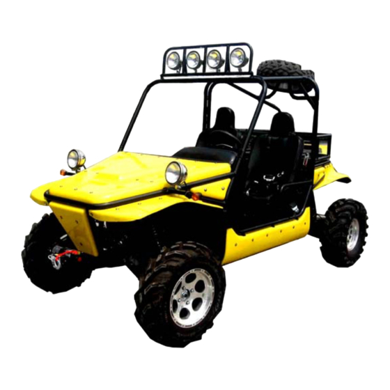
TROOPER
T2,T4
1
Advertisement
Table of Contents


Need help?
Do you have a question about the TROOPER T2 and is the answer not in the manual?
Questions and answers
What’s the part number to the radiator?
The radiator part number for the Joyner TROOPER T2 is not provided in the given context.
This answer is automatically generated