
Related Manuals for Joyner JNSZ650UV


Summary of Contents for Joyner JNSZ650UV
- Page 1 READ THIS MANUAL CAREFULLY It contains important safety information Owner’s manual JNSZ650UV...
-
Page 2: Table Of Contents
JOYNER, you can now appreciate the high degree of craftsmanship and reliability that have made JOYNER a leader in this field .This manual will provide you with a good basic understanding of the features and operation of this vehicle. It also includes basic maintenance and inspection procedures. -
Page 3: Location Of The Warning And Specification Labels
Never remove any labels from your vehicle. If a label becomes difficult to read or comes off, a replacement label is available from your Joyner dealer. W AR N I N G The enclosure cannot protect occupants in all foreseeable accidents,including rollover. - Page 4 W AR N I N G IMPROPER TIRE PRESSURE OR OVERLOADING CAN CAUSE LOSS OF CONTROL. LOSS OF CONTROL CAN RESULT IN SEVER INJURY OR DEATH. OPERATING TIRE PRESSURE:Set with tires cold. RECOMMENDED:FRONT:210kPa, 2.1kg/cm2,30psi REAR: 210kPa, 2.1kg/cm2,30psi Never set tire pressure below minimun.Tire may dislodge from rim.
- Page 5 W AR N I N G Severe INJURY or DEATH can result if you ignore the following: Maximum Load in Cargo Bed:350kg.(770lbs). Never carry passengers in cargo bed. Cargo can affect handling and stability.Read Owner's Manual before loading or towing. When loading with cargo or towing a trailer:Reduce speed and allow more room to stop.Avoid hills and rough terrain Be sure cargo is secured,a loose load could change handling...
- Page 6 W AR N I N G Improperly loading a trailer W AR N I N G and failure to use extra care when pulling trailer can cause an accident or injury. Never load more than 50kg (110lbs) tongue weight on the towing bracket.
- Page 7 This off-highway utility vehicle handles differently from other vehicles including cars and ATVs. SEVERE INJURY OR DEATH can result if you do not follow these instructions: Read this manual and all labels carefully and follow the operating procedures described. This vehicle is designed to carry the driver and one passenger. Never carry passengers in the cargo bed.
-
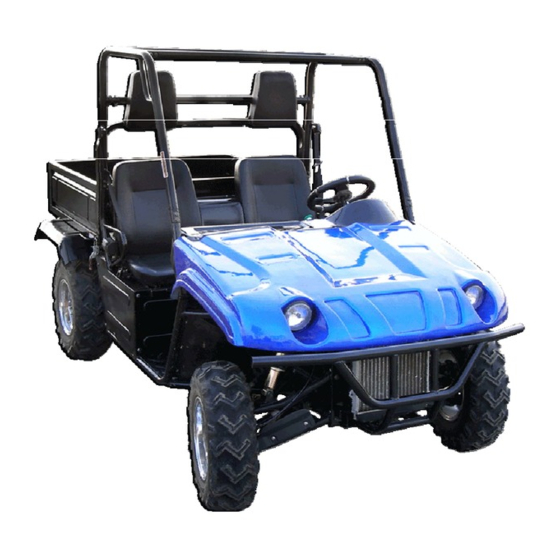
Page 8: Vehicle Description
Never operate on hills that are slippery or ones where you will not be able to see far enough ahead of you. Never go over the top of a hill at speed if you cannot see what is on the other side. Always follow proper procedures for going uphill. -
Page 9: Control Functions
16 Steering wheel 17 Starter (choke) 18 Main switch 19 On-Command four-wheel drive switch 20 Multi-function meter unit 21 Drive select lever 22 Parking brake lever 23 Accelerator pedal 24 Brake pedal Figure 2 25 Clutch pedal 26 CD player CONTROL FUNCTIONS Main switch Functions of the respective switch positions... -
Page 10: Light Switch
Multi-function meter unit coolant temperature indicator 3. power indicator 1. turn left indicator 4. turn right indicator 5. speedometer 6. gasoline quantity meter 7. coolant thermometer 8. 2WD/4WD indicator 9. odometer/ hour meter 10. tachometer 11. button 1 12. button 2 The multi-function meter unit is equipped with the following: ●... -
Page 11: Indicator Lights
Set the switch to “ ” to turn on the low beam and the taillights. Set the switch to “ ” to turn on the high beam and the taillights. Do not use the headlights with the engine turned off for an extended period of time.The battery may discharge to the point that the starter motor will not operate properly. -
Page 12: Drive Select Lever
Push button Speaker push button Press the button, speaker sound. Pedal Clutch pedal Press the clutch pedal before you shift by moving the drive select lever. Brake pedal Press the brake pedal to slow or stop the vehicle. Accelerator pedal Press the accelerator pedal down to increase engine speed. - Page 13 counterclockwise. Seats belts This vehicle is equipped with three-point seat belts for both the operator and passenger. Always wear the seat belt while riding in the vehicle. To wear the seat belt properly, do the following 1.Hold the latch plate as you pull the bell across your lap and chest. Make sure the belt is not twisted and is not caught on any portion of the vehicle, your clothing, or any equipment you are carrying.
-
Page 14: Cargo Bed
Cargo bed Opening and closing the tailgate To open Unhook the latches, and then lower the tailgate. To close Place the tailgate in the original position, and then hook the latches Lifting and lowering the cargo bed To lift Unhook the cargo bed latches on the left or right side of the vehicle, and then slowly lift up the cargo bed until it stops. -
Page 15: Drive Training
jacket whenever you drive. Although complete protection is not possible, wearing proper gear can reduce the chance of injury when you drive. The following suggestions will help you choose the proper driving gear. Helmets and Eyes Protection Your helmet is your most important piece of driving gear because it offers the best protection against head injuries. -
Page 16: Age Recommendation
Attempt supporting with your hands to the ground when the Go-cart turning over could lead to serious injury or death. Never support with your hands to ground when the Go-cat will turn over. Age Recommendation It is strongly recommended that no one under the age of 16 be permitted this UV650 without adult supervision. - Page 17 you find are corrected. A pre-drive inspection is a must, not only for safety, but because having a breakdown, or even a flat tire, can be a major inconvenience. If your UV650 has overturned or has been involved in a collision, do not drive it until your UV650 has been inspected by your dealer, There may be damages or other problems you can not see.
-
Page 18: Safe Driving Precautions
Lights ■ Make sure the headlight, brake light and tail light are working properly. Throttle ■ Check the free play and adjust if needed. Press the throttle to make sure it moves smoothly without sticking, and snaps back automatically when it is released. Clutch cable ■... -
Page 19: Control Speed
When driving off-road, also remember to always obey local off-road driving laws and regulations. Obtain permission to drive on private property. Avoid posted areas and obey “no trespassing” signs. You should never drive your UV650 on public streets, roads or highways, even if they are not paved. - Page 20 Operating this UV650 at excessive speeds increases your changes of losing control of the UV650, which can result in an accident. Always drive at a speed that is proper for your UV650, the terrain, visibility and other operating conditions, and your experience. Use Care on Unfamiliar or Rough Terrain Before driving in a new area, always check the terrain thoroughly.
-
Page 21: Specifications
SPECIFICATIONS Model JNSZ650UV Dimensions: Overall length 2980mm Overall width 1435mm Overall height 1820mm Seat height 770mm Wheelbase 1231mm Ground clearance 280mm Minimum turning radius 4500mm Basic weight: With oil and full fuel tank 645kg Engine: Engine type Liquid cooled—4stroke Cylinder arrangement... - Page 22 Fuel: Type Unleaded gasoline only Fuel tank capacity Carburetor: Type P32Q-1 Spark plug: Type/manufacturer T4196J Spark plug gap 0.7±0.1mm Clutch type: Dry,digphragm spring Transmission: Crank to primary shaft 33/17(1.941) Primary to secondary One: 36/17(2.118) Two: 29/22(1.318) Three: 23/27(0.852) Reverse: 33/15(2.2) Final One: 4.111 Two:2.559...
-
Page 23: Operation
Electrical: Ignition system Distributor block Generator system AC magneto Battery type Lead acid storage battery Battery capacity 12V 36Ah Specified fuses: Main fuse Headlight fuse Signaling system fuse Bulb voltage, wattage×quantity: 12V 35W/35W×2 Headlight Tail/brake light 12V 5W/21W×2 Indicator lights: Reverse indicator light Coolant temperature warning light Parking brake indicator light... - Page 24 Throttle Figure 3 The right foot pedal is the throttle that controls the UV650 speed. To disengage the clutch at any time, allow the throttle to return to the idle position. (See Fig. 3) Each time prior to starting the engine, check the throttle assembly to ensure that when pedal is pushed all the way forward the assembly is working smoothly and returns to idle when released.
- Page 25 3. Turn the key clockwise to the “on” position. Release the key and the clutch pedal when the engine starts. 4. Push the choke back slowly to allow the engine to run smoothly. Keep engine running for 1-2 minutes. 5. Push the choke back fully. If the idle of engine is not smooth, pull out the choke to find the best running position and keep running for a while long until the engine running smooth without choke.
- Page 26 If the engine does not start after 5 seconds, a second attempt to start the engine can be allowed. Improper operation will damage the engine. Engine stop key Before driving this vehicle, test the Engine Stop key to assure that it is operating properly.
-
Page 27: Seat Adjustment
Always follow rules for safe operation and wear a helmet. Passengers The vehicle allows for two riders only. Combined maximum weight of driver and the passenger should not exceed 180kg or 400Ibs. Seat Adjustment The seat must always be securely fastened in the position which best allows the operator control of the foot pedals, steering wheel, and the remote... - Page 28 Parking Adjustment Park brake “OFF” Park brake “On” Figure 6 Figure 7 Pull the park brake lever up so that the unit can engage park brake. To release the unit, press button on front end of parking lever then push the parking lever to the bottom.
-
Page 29: Starting And Operating Instructions
Gear 15km/h Gear 25km/h Max speed in each gear Gear 35km/h Gear 55km/h Starting And Operating Instructions Before starting the engine, be sure that the driver is seated properly in UV650 and tighten the seatbelt. Testing the UV650 in a open place at the beginning to learn how to start, turn and stop. -
Page 30: Transmission Lubrication
Figure 10 Figure 11 Figure 12 Figure 13 a. With the engine warm, put the vehicle on the level ground. b. Shut down the engine, put a collecting oil plate under the engine oil outlet. Loosen the oil outlet plug in the warm engine. Let the engine oil out fully (see Fig. -
Page 31: Engine Coolant
Figure 14 Figure 15 a. Put the vehicle on the level ground. b. Shut down the engine, put a collecting oil plate under the transmission oil outlet. Loosen the oil outlet plug in the warm engine. Let the transmission oil out fully (see Fig. - Page 32 1. Turn the coolant cap counterclockwise and open the cap (see Fig. 16). 2. Pour fresh coolant to filler neck. 3. Start the engine at idle. 4. Increase the engine rev a few times 5. Repeat 2,3,4 till the coolant is at neck and no bubbles come up. 6.
-
Page 33: Spark Plug
Spark Plug Remove the spark plug and inspect it each time you change the oil. (Use a spark plug wrench) The electrodes should be kept clean and free of carbon. The presence of carbon or excess oil will greatly reduce proper engine performance. If possible, check the spark plug gap (area between electrodes) using a wire feeler gauge. -
Page 34: Repair
REPAIR Front Wheel Replacement Do not disassemble the center castle nuts when you replace the front wheels.(See Fig. 20) Tighten the nuts after replacing the wheels. Figure 20 Rear Wheel Replacement Do not disassemble the center castle nuts when you replace the front wheels.(See Fig. 21) Tighten the nuts after replacing the wheels. -
Page 35: Clutch Replacement
Figure 21 Clutch replacement Do not remove the whole engine from vehicle when you replace the clutch, but you’ll need to remove rear suspension, driven shaft, clutch cable, muffler, wires and rubber cushion that is in the middle of transmission and frame. 1. - Page 36 Figure 23 Figure 24 3. Remove two nuts (M14) on two side of transmission (See Fig. 25, 26) Figure 25 Figure 26 1. Remove two bolts(M8) on the low mud plate of transmission (See Fig. 27, 28) Figure 27 Figure 28 2.
- Page 37 Figure 30 Figure 30 Figure 31 4. Remove upper mud plate (See Fig. 32) Figure 32 5. Insert a shaft into the hole (See Fig. 33). Remove six bolts on the pressing plate of clutch (See Fig. 34)
- Page 38 Figure 33 Figure 34 6. Remove the pressure plate (See Fig. 35). Remove the friction disc of clutch (See Fig. 36, 37) Figure 35 Figure 36 Figure 37 10. Insert a special shaft into the hole, fix new friction plate on the flywheel of engine (See Fig.
-
Page 39: Timing Chain
11. Fix pressure plate of clutch. Two bolts with “Y.G” mark must be inserted into two anchor hole (See Fig. 40) . Tighten six bolts with torque 30 N.m (See Fig. 41) Figure 40 Figure 41 12. Fix upper mud plate (See Fig. 42, 43) Figure 42 Figure 43 13. - Page 40 Distributor replacement 1 turn around the crank shaft (See Fig. 44), direct the line on the pulley of crankshaft straight to the 0 degree line on the cover of engine (See Fig. 46) Figure 44 Figure 45...
- Page 41 Figure 46 2. Remove the rocker cover of head by removing two bolts (See Fig. 47) Figure 47 3. Check the anchor hole, if it is not on the direction shown by Fig. Repeat above 1 as to obtain the hole direction shown by Fig.
- Page 42 3. Insert the screwdriver into the hole, turn the drive of oil pump shaft untill parallel to the crankshaft (See Fig. 48,49) Figure 48 Figure 49 4. Align the mark 2 on the shaft of distributor to the mark 1 on the aluminum housing (See Fig.
-
Page 43: Front Wheel Alignment
Figure 52 Figure 53 6. Fix the cover of the distributor (See Fig. 44). Figure 42 7. Check the spark timing. Adjust if need as followings Loosen the nut of the distributor housing Turn the distributor slowly. Increase the spark timing by counterclockwise turn. Decrease the spark timing by clockwise turn. -
Page 44: Periodic Maintenance
PERIODIC MAINTENANCE The maintenance intervals in the following table are based upon average driving conditions. Driving in unusually dusty areas, require more frequent servicing. Time of service Initial Monthly Quarterly Yearly service Item Engine 1. driven belt 2. Tighten bolts on engine. 3. -
Page 45: Cleaning And Storage
20. Parking 21. Brake shoes and disc Chassis 22. Tires 23. Tighten nuts on the hub and wheel 24. Shocks 25. Driven shaft 26. All nuts and bolts 27. Steering wheel, steering 28. Test vehicle A: adjust C: clean I: inspect, clean or replace if necessary. L: lubricate R: replace CLEANING AND STORAGE Cleaning Frequent, thorough cleaning of your vehicle will not only enhance its appearance but will... -
Page 46: Wiring Diagram
6.Clean the seats with a vinyl upholstery cleaner to keep the cover pliable and glossy. 7.Automotive type wax may be applied to all painted and chrome plated surfaces. Avoid combination cleaner-waxes. Many contain abrasives which may scratch the paint or protective finish. When finished, start the engine and let it idle for several minutes. -
Page 48: Jnsz650Uv Limitied Warranty
Should warranty service be required on your JNSZ650UV during the 90 days warranty period, please contact your nearest authorized dealer for repairs. What is not covered under this warranty This warranty does not cover any seller vehicle that has been subjected to: a.
Need help?
Do you have a question about the JNSZ650UV and is the answer not in the manual?
Questions and answers
Size motor is it
The motor size for the Joyner JNSZ650UV is 650cc.
This answer is automatically generated