
Related Manuals for KTI Networks KGS-0841-W


Summary of Contents for KTI Networks KGS-0841-W
- Page 1 KGS-0841-W KGS-0860-WP KGS-0861-WP KGS-0862-WP KGS-0863-WP IP65/67 Rated Gigabit Ethernet Switches Firmware Rev1.04 up User’s Manual DOC.150331...
- Page 2 (such as translation or transformation) without permission from KTI Networks Inc. KTI Networks Inc. reserves the right to revise this documentation and to make changes in content from time to time without obligation on the part of KTI Networks Inc. to provide notification of such revision or change.
- Page 3 The information contained in this document is subject to change without prior notice. Copyright ©All Rights Reserved. TRADEMARKS Ethernet is a registered trademark of Xerox Corp. FCC NOTICE This device complies with Part 15 of the FCC Rules. Operation is subject to the following two conditions: (1) This device may not cause harmful interference, and (2) This device must accept any interference received, including the interference that may cause undesired operation.
-
Page 4: Table Of Contents
Table of Contents 1. Introduction ..............................7 1.1 Features..........................8 1.2 Product Model Options ......................8 1.3 Product Panels........................10 1.3.1 KGS-0841-W........................10 1.3.2 KGS-0860-WP ........................10 1.3.3 KGS-0861-WP ........................11 1.3.4 KGS-0862-WP ........................11 1.3.5 KGS-0863-WP ........................12 1.3.6 KGS-086x-WP Fiber Interfaces ..................13 1.4 LED Indicators ........................ - Page 5 3.3 Console Commands ......................45 3.4 IP Commands ........................47 4. Web Management ............................50 4.1 Start Browser Software and Making Connection ..............50 4.2 Login to the Switch Unit ....................... 50 4.3 Main Management Menu ..................... 53 4.4 System ..........................55 4.4.1 Management VLAN......................
- Page 6 4.12.2 802.1p Mapping ......................94 4.12.3 DSCP Mapping ....................... 95 4.12.4 QoS Service Policy ......................96 4.13 Storm Control........................97 4.14 Multi Ring ........................... 98 4.15 Statistics Overview......................99 4.16 Detailed Statistics ......................100 4.17 LACP Status ........................101 4.18 RSTP Status ........................103 4.19 IGMP Status........................
-
Page 7: Introduction
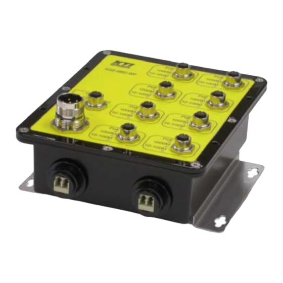
1. Introduction KTI’s KGS-0860 IP65/67 switch series offers a diverse range of managed Ethernet switches with the ruggedized hardware design for protection against strong jets of water and temporary immersion in water. The series includes a variety of 8-ports switches featured with different configurations composed of Fast Ethernet ports and Gigabit Ethernet ports. -
Page 8: Features
Support either direct DC input or PoE over network cable Offer optional high power PoE+ PSE switch models 1.2 Product Model Options Model Name Managed Fast Ethernet Gigabit Ethernet Fiber options PoE feature KGS-0841-W 8 ports KGS-0860-WP 8 ports KGS-0860-WP-x 8 ports 1 100Base-FX ... - Page 9 *1: Additional 100Base-FX fiber interface on Port #8 *2: Additional two 100Base-FX fiber interfaces on Port #7 and Port #8 *3: Additional 1000Base-X fiber interface on Port #8 *4: Additional two 1000Base-X fiber interfaces on Port #7 and Port #8 *5: PoE PD function on Port #4 (The switch can be powered via PoE on Port #4.) *6: All ports are featured with PoE+ PSE function.
-
Page 10: Product Panels
1.3 Product Panels 1.3.1 KGS-0841-W 1.3.2 KGS-0860-WP... -
Page 11: Kgs-0861-Wp
1.3.3 KGS-0861-WP 1.3.4 KGS-0862-WP... -
Page 12: Kgs-0863-Wp
1.3.5 KGS-0863-WP... -
Page 13: Kgs-086X-Wp Fiber Interfaces
1.3.6 KGS-086x-WP Fiber Interfaces The following figures illustrate the fiber interfaces of the models with fiber options: No fiber interface One fiber interface Two fiber interfaces... -
Page 14: Led Indicators
1.4 LED Indicators Function POWER Power status 1000M 1000M link & activities status (Gigabit Ethernet ports) 10-100M 10M or 100M link & activities status (Gigabit Ethernet ports) 100M 100M link & activities status (Fast Ethernet ports) 10M link & activities status (Fast Ethernet ports) PoE power status (PoE input ports, PoE output ports) Port 7 fiber transceiver in use Port 8 fiber transceiver in use... - Page 15 Pin# PoE Input LAN Signal Power polarity protection Fast Ethernet (FE) Port built-in PoE Output PoE Standard IEEE 802.3at PSE (High power PoE+) PD Support Type 1 Class 0 ~ 3, Type 2 Class 4 Power Delivery 30W max. (per port) Protection Under voltage, Over voltage, Over current, Over temperature PSE Power Pins...
- Page 16 Gigabit Ethernet (GbE) Port built-in PoE Input Standard IEEE 802.3af PD (Powered Device) PSE Support IEEE 802.3af & 802.3at PSE Power Classification Class 0 Input Voltage (V 36 ~ 57VDC via Cat.5 Power Reception Pin assignments Pin# Signal Power polarity protection Gigabit Ethernet (GbE) Port built-in PoE Output PoE Standard IEEE 802.3at PSE (High power PoE+)
- Page 17 Configuration 100Mbps, Full duplex Transmission rate 100Mbps Network cables MMF 50/125 60/125, SMF 9/125 Eye safety IEC 825 compliant Optical Specifications Refer to Appendix X for variety of fiber options 1000Base-X Fiber interface Compliance 1000Base-SX/LX/BX Connector LC for single fiber, Dual LC for duplex fiber Configuration Auto/Forced, 1000Mbps, Full duplex Transmission rate...
- Page 18 +51 ~ +57VDC for support Type 1 and Type 2 PDs * Warning: The -48VDC power supply is not supported. Power Consumption 11.5W max. (No PoE support) Pin Assignments Pin# Signal Frame Ground 4, 5, 6 Insulation FG vs. DC power lines (500VDC/10M-Ohm) Switch Functions MAC Addresses Table 8K entries...
- Page 19 EN 55011, EN 61000-3-2, EN 61000-3-3 EN 61000-6-2 industrial environment IEC 60068-2-1 cold temperature test IEC 60068-2-2 dry heat test IEC 60068-2-30 damp heat test IEC 60068-2-48 storage temperature test IEC 60068-2-27 shock test EN 50155 railway applications for rolling stock NEMA TS2 Environment IPX5 water jets test IPX7 water immersion test...
-
Page 20: Installation
2. Installation 2.1 Unpacking The product package contains: The switch unit One accessory kit One product CD-ROM 2.1.1 Package Accessory Kit Panel mount bracket 1 pc M4-6mm screw (for panel mounting) 4 pcs PWR3PE-PMF-2 DC power cable 2 meters 1 pc C5EFPE-CMR-2 Console cable 2 meters 1 pc... -
Page 21: Panel Mounting
2.3 Panel Mounting One stainless panel mount bracket is included in product package as shown below: Install the bracket on the bottom with M4 screws. - Page 22 There is one screw is provided on panel mount bracket. It can be used for PE (Protective Earth) connection if needed. Dimension of the device with mounting bracket...
-
Page 23: Flat Mounting
2.4 Flat Mounting The device can support flat mount onto a flat panel face as illustrated below: There are four screw holes located on the front. Use M5-15mm screw for fixing the device on the flat panel. After installation... -
Page 24: Applying Power
1. Direct DC power input via Power connector 2. PoE power input via Port 4 The table below lists the available power method for different models: Model Name PoE feature Direct DC PoE via Port 4 KGS-0841-W KGS-0860-WP-xx KGS-0861-WP-xx ... - Page 25 Use appropriate power cable as shown below to supply DC power from external power supply. The pin assignments are: Pin# Contacts Frame Ground 4, 5, 6 Pin #3 connects to device frame ground and it is isolated from power lines DC+/DC-. It can be used for PE (Protective Earth) connection.
-
Page 26: Powered Via Poe Over Cat.5
The working voltages and maximal power required for different applications are listed as follows: Model Name Application Operating voltage range Max. power KGS-0841-W General +6.5 ~ +60VDC 11.5W KGS-0860-WP-xx General +6.5 ~ +60VDC 11.5W KGS-0861-WP-xx General +6.5 ~ +60VDC 11.5W... -
Page 28: Making Cat.5 Connections
2.6 Making Cat.5 Connections 2.6.1 Patch Cables for Fast Ethernet Port Types Types: Fast Ethernet Ports (Typical) Fast Ethernet Ports with built-in PoE power input Fast Ethernet Ports with built-in PoE power output (PSE) Available patch cable specifications IP65/67 protection with M12 connector ... -
Page 29: Patch Cables For Gigabit Ethernet Port Types
Cable Pin Assignments 2.6.2 Patch Cables for Gigabit Ethernet Port Types Types: Gigabit Ethernet Ports (Typical) Gigabit Ethernet Ports with built-in PoE power input Gigabit Ethernet Ports with built-in PoE power output (PSE) Available patch cable specifications IP65/67 protection with M12 connector ... - Page 30 Cable Pin Assignments Plug cable to the device and screw it securely.
-
Page 31: Important Functions Of M12 Copper Ports
2.6.3 Important Functions of M12 Copper Ports Auto MDI/MDI-X Function This function allows the port to auto-detect the twisted-pair signals and adapts itself to form a valid MDI to MDI-X connection with the remote connected device automatically. No matter a straight through cable or crossover cable connected, the ports can sense the receiving pair automatically and configure self to match the rule for MDI to MDI-X connection. -
Page 32: Making Console Connection
2.7 Making Console Connection Use the listed cable below for console connection. Cable Pin Assignments Baud Rate information: Baud rate – 115200 Data bits - 8 Parity – None Stop bit – 1 Flow control – None Plug the cable to the console port and screw it securely. -
Page 33: Making Poe Pse Connection To Pd Device
2.8 Making PoE PSE Connection to PD Device Cables No special cable is required for this connection. Depending on the port types, use the suggested cables listed in Section 2.6.1 and 2.6.2. Typical PoE Applications Supported Powered Devices (PD): 802.3af compliant devices PoE Power output: 15.4W max. - Page 34 High Power PoE Applications The switches can support PoE high power applications. It means the power delivered can be up to 30watts by single PSE port connection to a PD device which consumes larges power than typical PoE 15.4W. Supported Powered Devices (PD): 802.3af or 802.3at compliant devices PoE Power output: 30W max.
-
Page 35: Making Fiber Connection
2.9 Making Fiber Connection Some models provide optional fiber interfaces for Port #8 or Port #7 and Port #8 both as shown below: The fiber interface may come with one LC connector for single fiber cable or come with two LC connectors for duplex fiber cables depending on the model optical specification. - Page 36 Cable Installation for IP67 For IP65 and IP67 protection, one optional fiber accessory part, FO-PLUG-P-L is required for fiber cable installation. The part is for protection purpose only. FO-PLUG-P-L Fiber port plug kit, IP67 rated The installation of the part with fiber cable is shown as follows: There are four seals packed in the kit.
-
Page 37: Led Indication
2.10 LED Indication ___________________________________________________________________________________________________________________________________________________ Function ___________________________________________________________________________________________________________________________________________________ POWER Power status ON: power on OFF: power off ___________________________________________________________________________________________________________________________________________________ 1000M 1000M link & activities status (Gigabit Ethernet ports) ON: port link on, speed 1000M BLINK: data in transmission OFF: port link off ___________________________________________________________________________________________________________________________________________________ 10-100M 10M or 100M link &... -
Page 38: Configuring Ip Address For The Switch
2.11 Configuring IP Address for the Switch The switch is shipped with the following factory default settings for software management: Default IP address of the switch: 192.168.0.2 / 255.255.255.0 The IP Address is an identification of the switch in a TCP/IP network. Each switch should be designated a new and unique IP address in the network. - Page 39 User Priority: 3-bit field refer to the 802.1p priority CFI: The Canonical Format Indicator for the MAC address is a 1 bit field. VID: VLAN identifier, 12-bit field identifies the VLAN to which the frame belongs to. Untagged packet: A standard Ethernet frame with no VLAN Tag field Priority-tagged packet: An IEEE 802.1Q packet which VID filed value is zero (VID=0) VLAN-Tagged packet: An IEEE 802.1Q packet which VID filed value is not zero (VID<>0) PVID (Port VID): PVID is the default VID of an ingress port.
-
Page 40: Console Command Line Interface
3. Console Command Line Interface 3.1 Console CLI System Boot Up Message Enter default Password: 123 to enter CLI mode. Top level commands Press ? or help to get help. The help depends on the context: - At top level, a list of command groups will be shown. - At group level, a list of the command syntaxes will be shown. - Page 41 System Trap [<IP Address>] System Readcommunity [<community string>] System Writecommunity [<community string>] System Trapcommunity [<community string>] System Power Saving [full|up|down|disable] Configuration ___________________________________________________________________________________________________________________________________________________ System>Config help Syntax: System Configuration [all] Description: Show system name, software version, hardware version and management MAC address. [all]: Show the total switch configuration (default: System configuration only) System>Config System Configuration:...
- Page 42 Name ___________________________________________________________________________________________________________________________________________________ System>Name help Syntax: System Name [<name>] Description: Set or show the system name. [<name>]: String of up to 16 characters (default: Show system name). Reboot ___________________________________________________________________________________________________________________________________________________ System>Reboot help Syntax: System Reboot Description: Reboot the switch. SNMP ___________________________________________________________________________________________________________________________________________________ System>SNMP help Syntax: SNMP [enable|disable] Description:...
- Page 43 Readcommunity ___________________________________________________________________________________________________________________________________________________ System>Readcommunity help Syntax: Readcommunity [<community string>] Description: Set or show SNMP read community string. [<community string>]: New community string. (default: Show current value). Writecommunity ___________________________________________________________________________________________________________________________________________________ System>Writecommunity help Syntax: Writecommunity [<community string>] Description: Set or show SNMP write community string. [<community string>]: New community string.
- Page 44 full: Power saving at both link-up and link-down. Power saving at link-up only. down: Power saving at link-down only. disable: No power saving.
-
Page 45: Console Commands
3.3 Console Commands Console>? Commands at Console level: Console Configuration Console Password [<password>] Console Timeout [<timeout>] Console Prompt [<prompt string>] Configuration ___________________________________________________________________________________________________________________________________________________ Console> Configuration help Syntax: Console Configuration Description: Show configured console password and timeout. Password ___________________________________________________________________________________________________________________________________________________ Console>Password help Syntax: Console Password [<password>] Description: Set or show the console password. - Page 46 Syntax: Console Prompt [<prompt_string>] Description: Set or show the console prompt string. [<prompt_string>]: Command prompt string of up to 10 characters.
-
Page 47: Ip Commands
3.4 IP Commands IP>help Commands at IP level: Configuration Status Setup [<ipaddress> [<ipmask> [<ipgateway>]]] [<vid>] Mode [enable|disable] Ping [-n <count>] [-w <timeout>] <ipaddress> Dhcp [enable|disable] Configuration ___________________________________________________________________________________________________________________________________________________ IP>Configuration help Syntax: IP Configuration Description: Show IP configured IP address, mask, gateway, VLAN ID and mode. IP>config IP Configuration: Address: 192.168.0.2... - Page 48 Description: Show current IP status. Setup ___________________________________________________________________________________________________________________________________________________ IP>Setup help Syntax: IP Setup [<ipaddress> [<ipmask> [<ipgateway>]]] [<vid>] Description: Setup or show IP configuration. [<ipaddress>]: IP address. (default: Show IP configuration) [<ipmask>]: IP subnet mask (default: Subnet mask for address class). [<ipgateway>]: Default IP gateway, (default: 0.0.0.0).
- Page 49 ___________________________________________________________________________________________________________________________________________________ IP>Arp help Syntax: IP Arp Description: Show the content of the ARP table. Dhcp ___________________________________________________________________________________________________________________________________________________ IP>Dhcp help Syntax: IP DHCP [enable|disable] Description: Activate or deactivate the DHCP protocol. [enable|disable]: Enable/disable DHCP (default: Show DHCP mode). -49-...
-
Page 50: Web Management
4. Web Management The switch features an http server which can serve the management requests coming from any web browser software over TCP/IP network. Compatible Web Browser Compatible web browser software with JAVA script support Microsoft Internet Explorer 6.0 or later Google Chrome Mozilla Firefox Set IP Address for the System Unit... - Page 51 Factory default password: 123 The switch will accept only one successful IP connection at the same time. The other connection attempts will be prompted with a warning message as the right is played above. A new connection will be accepted when the current user logout successfully or auto logout by the switch due to no access for time out of 300 seconds.
- Page 52 -52-...
-
Page 53: Main Management Menu
4.3 Main Management Menu Configuration System Switch information, system and IP related settings Ports Port link status, port operation mode configuration VLAN VLAN related configuration LACP LACP configuration for port link aggregation RSTP RSTP (Rapid spanning tree protocol) related configuration 802.1X 802.1X authentication related configuration IGMP Snooping... - Page 54 Monitoring Statistics Overview List simple statistics for all ports Detailed Statistics List detailed statistics for all ports LACP Status LACP port status RSTP Status RSTP protocol status IGMP Status IGMP snooping status PoE Status Power over Ethernet function status Multi Ring Status Multi redundant ring status Ping Ping command from the switch to other IP devices...
-
Page 55: System
4.4 System ___________________________________________________________________________________________________________________________________________________ Configuration Description ___________________________________________________________________________________________________________________________________________________ MAC Address The MAC address factory configured for the switch. It can not be changed in any cases. S/W Version Firmware version currently running H/W Version Hardware version currently operating Active IP Address Current IP address for the switch management -55-... - Page 56 Active Subnet Mask Current subnet mask for IP address for the switch management Active Gateway Current gateway IP address for the switch management DHCP Server Current IP address of the DHCP server Lease Time Left The time left for the lease IP address currently used DHCP Enabled Use DHCP to get dynamic IP address configuration for the switch Fallback IP Address...
-
Page 57: Management Vlan
4.4.1 Management VLAN Management VLAN settings allow administrator to access the switch and perform the switch management over a dedicated VLAN. The following rules are applied with the Management VLAN: 1. If [Management VLAN] setting is zero, no VLAN limitation is applied in accessing the switch web management interface. -
Page 58: Ports
4.5 Ports ___________________________________________________________________________________________________________________________________________________ Configuration Function ___________________________________________________________________________________________________________________________________________________ Enable Jumbo Frames Set to enable jumbo frame support Power Saving Mode Full - all the time Link-up - power saving only when link up Link-down - power saving only when link down Disable - disable port power saving Port The port number Indicates Port 8 media type –... - Page 59 Down with red background - port is link down Mode Select port operating mode Disabled - disable the port operation Mode Auto-negotiation Speed capability Duplex capability Auto Enable 10, 100, 1000M Full, Half 10 Half Disable Half 10 Full Disable Full 100 Half Disable...
-
Page 60: Port Type
4.5.1 Port Type Port 7 and Port 8 supports two media types, M12 copper and FX fiber interface. Use this button to select the port type. ___________________________________________________________________________________________________________________________________________________ Information Function ___________________________________________________________________________________________________________________________________________________ Port # Port number (Port 7 & Port 8) Only Port 7 and Port 8 support dual media types, M12 copper and FX fiber and the available options are model-dependent. -
Page 61: Fx Ddm Status
4.5.2 FX DDM Status DDM (Digital Diagnostic Monitoring) information and status are provided in some transceivers. Part of the information are retrieved and listed as follows: ___________________________________________________________________________________________________________________________________________________ Information Function ___________________________________________________________________________________________________________________________________________________ Port Port number which has fiber interface Identifier The identifier information of the fiber transceiver Connector The connector type used on the fiber transceiver SONET Compliance... -
Page 62: Vlans
4.6 VLANs ___________________________________________________________________________________________________________________________________________________ VLAN Configuration Description ___________________________________________________________________________________________________________________________________________________ VLAN Disable Select to disable VLAN function All ports are allowed to communicate with each others freely with no VLAN limitation. Port-based VLAN Mode Simple configuration for 2 port-based VLAN groups Port-based VLAN ISP Mode Simple configuration for 7 port-based VLAN groups (also called metro-mode sometimes) Simplified Tag-based VLAN Mode Simple configuration for Tag-based VLAN (Less optional settings) -
Page 63: Vlan Function
4.6.1 VLAN Function The switch can support port-based VLAN, 802.1Q Tag VLAN and eight VLAN groups. The following figure illustrates the basic VLAN operation flow beginning from a packet received on an ingress port until it is transmitted from an egress port. The following sections describe the VLAN processes and Advanced VLAN mode settings provided by the switch. - Page 64 Keep Tag Per port setting Enable - The VLAN tag in the received VLAN tagged packet will be kept as it is and is not stripped in whole forwarding operation. Disable - The VLAN tag data in the received VLAN tagged packet is stripped (removed). Drop Untag Per Port Setting Enable - All untagged packets and priority-tagged packets are dropped.
- Page 65 VLAN Group Table Configuration The switch provides a table of eight VLAN groups to support up to eight VLANs at the same time. Each VLAN group is associated to one unique VLAN. The table is referred for VLAN classification. A VLAN group contains the following configuration settings: VID: 12-bit VLAN Identifier index to the VLAN to which the group is associated Member Ports:...
- Page 66 Egress Tagging Rules Egress Tagging rules are used to make change to the packet before it is stored into egress queue of an egress port. The egress settings are provided for each port and are described as follows: Egress Settings Insert Tag (per port setting) Enable - Insert the Tag data of the associated Packet Tag information into the packet...
-
Page 67: Port-Based Vlan Mode
4.6.2 Port-based VLAN Mode => ___________________________________________________________________________________________________________________________________________________ Configuration Description ___________________________________________________________________________________________________________________________________________________ Group 1, 2 Port-based VLAN group number Member ports Select member ports for the group ___________________________________________________________________________________________________________________________________________________ [Apply] Click to apply the configuration change [Refresh] Click to refresh current configuration [Back] Click to go back to upper menu ___________________________________________________________________________________________________________________________________________________ Operation in this mode: 1. -
Page 68: Port-Based Vlan Isp Mode
4.6.3 Port-based VLAN ISP Mode => ___________________________________________________________________________________________________________________________________________________ Configuration Description ___________________________________________________________________________________________________________________________________________________ Joint port Select a port as the joint port for all 7 port-based VLAN groups ___________________________________________________________________________________________________________________________________________________ [Apply] Click to apply the configuration change [Refresh] Click to refresh current configuration [Back] Click to go back to upper menu ___________________________________________________________________________________________________________________________________________________ Example:... -
Page 69: Simplified Tag-Based Vlan Mode
4.6.4 Simplified Tag-based VLAN Mode => ___________________________________________________________________________________________________________________________________________________ Configuration Description ___________________________________________________________________________________________________________________________________________________ [VLAN Groups] Click to configure VLAN groups first [VLAN Per Port] Click to configure per port simplified VLAN settings ___________________________________________________________________________________________________________________________________________________ -69-... -
Page 70: Vlan Groups
4.6.4.1 VLAN Groups ___________________________________________________________________________________________________________________________________________________ Configuration Description ___________________________________________________________________________________________________________________________________________________ Group Group number VID of the VLAN to which this group is associated 1 ~ 4095 - decimal 12-bit VID value Member Ports Select the admitted egress ports for the packets belong to the VLAN Port 1 ~ 8 - click to select Source Port Check Check whether the ingress port is the member port of the VLAN... -
Page 71: Per Port Settings
4.6.4.2 Per Port Settings ___________________________________________________________________________________________________________________________________________________ Configuration Description ___________________________________________________________________________________________________________________________________________________ Port Port number PVID Port VID, VID of Ingress Default Tag (See section 4.6.4.1) 1 ~ 4095 - decimal 12-bit VID value Drop Untag Drop all untagged packets and priority-tagged packets (ingress) Enable - drop untagged packets and priority-tagged packets Disable - admit untagged packets and priority-tagged packets Egress Tagging... -
Page 72: Simplified Tag-Based Vlan Operation
4.6.4.3 Simplified Tag-based VLAN Operation Ingress filtering setting [Drop Untag] = Enable Ingress Packets Rule Untagged packets Dropped Priority packets Dropped Tagged packets Admitted to get into forwarding operation Ingress filtering setting [Drop Untag] = Disable Ingress Packets Rule Untagged packets Admitted to get into forwarding operation Priority packets Admitted to get into forwarding operation... - Page 73 Egress rule setting [Egress Tagging] = Specific Tag Ingress Packets Egress rule Untagged packets Tagging with Ingress Default Tag* (Tagging) Priority packets Tagging with Ingress Default Tag* (Tagging) Tagged packets Egress with no packet modification except the packets with VID equal to [Untagged VID] setting* * Ingress Default Tag = Ingress port PVID + CFI (0) + User priority (0) &...
-
Page 74: Advanced Vlan Mode
4.6.5 Advanced VLAN Mode ___________________________________________________________________________________________________________________________________________________ Configuration Description ___________________________________________________________________________________________________________________________________________________ Ingress Default Tag Click to configure per port Ingress Default Tag settings Ingress Settings Click to configure per port ingress settings Egress Settings Click to configure per port egress settings VLAN Groups Click to configure VLAN group table ___________________________________________________________________________________________________________________________________________________ -74-... -
Page 75: Ingress Default Tag
4.6.5.1 Ingress Default Tag ___________________________________________________________________________________________________________________________________________________ Configuration Description ___________________________________________________________________________________________________________________________________________________ Port Port number PVID Port VID, VID for Ingress Default Tag 1 ~ 4095 - decimal 12-bit VID value CFI for Ingress Default Tag 0, 1 - 1-bit CFI value User Priority User priority for Ingress Default Tag 0 ~ 7 - decimal 3-bit value ___________________________________________________________________________________________________________________________________________________... -
Page 76: Ingress Settings
4.6.5.2 Ingress Settings ___________________________________________________________________________________________________________________________________________________ Configuration Description ___________________________________________________________________________________________________________________________________________________ Port Port number Tag Aware Check tag data for every received packet Tag-aware - set to activate Tag-based mode Tag-ignore - set to use port-based mode and ignore any tag in packet Keep Tag Tag is removed from the received packet if exists Enable - set to activate tag removal for VLAN-tagged packets Disable - set to disable tag removal function... - Page 77 table lists the index used: Ingress [Tag Aware] setting Received packet type Tag-ignore Tag-aware Untagged PVID PVID Priority-tagged (VID=0) PVID PVID VLAN-tagged (VID>0) PVID Packet tag VID 3. Both [Drop Untag] and [Drop Tag] are set to Disable to admit all packets. -77-...
-
Page 78: Egress Settings
4.6.5.3 Egress Settings ___________________________________________________________________________________________________________________________________________________ Configuration Description ___________________________________________________________________________________________________________________________________________________ Port Port number Insert Tag Activate tagging (Insert a tag to the packet) Enable - set to activate tagging Disable - set to disable tagging function Untagging Specific VID No tag insertion if packet tag information matches [Untagged VID] Enable - set to enable this function Disable - set to disable this function Untagged VID... -
Page 79: Vlan Groups
4.6.5.4 VLAN Groups ___________________________________________________________________________________________________________________________________________________ Configuration Description ___________________________________________________________________________________________________________________________________________________ Group Group number VID of the VLAN to which this group is associated 1 ~ 4095 - decimal 12-bit VID value Member Ports Select the admitted egress ports for the packets belong to the VLAN Port 1 ~ 8 - click to select Source Port Check Check whether the ingress port is the member port of the VLAN... -
Page 80: Simplified Tag-Based Vlan Vs. Advanced Vlan
4.6.6 Simplified Tag-based VLAN vs. Advanced VLAN Simplified Tag-based mode comes from “Advanced” mode actually. Some optional settings in “Advanced” mode are pre-configured and hidden for no change under Simplified mode. The following table lists the setting relations between Simplified mode and Advanced: Hidden Advanced settings &... -
Page 81: Important Notes For Vlan Configuration
4.6.7 Important Notes for VLAN Configuration Some considerations should be checked in configuring VLAN settings: 1. Switch VLAN Mode selection It is suggested to evaluate your VLAN application first and plan your VLAN configuration carefully before applying it. Any incorrect setting might cause network problem. 2. -
Page 82: Lacp
4.7 LACP ___________________________________________________________________________________________________________________________________________________ Configuration Description ___________________________________________________________________________________________________________________________________________________ Port Port number Protocol Enabled Enable LACP support for the port Key Value An integer value assigned to the port that determines which ports are aggregated into an LACP link aggregate. Set same value to the ports in same LACP link aggregate. -
Page 83: Rstp
4.8 RSTP ___________________________________________________________________________________________________________________________________________________ Configuration Description ___________________________________________________________________________________________________________________________________________________ System Priority The lower the bridge priority is the higher priority it has. Usually, the bridge with the highest bridge priority is the root. Value: 0 ~ 61440 Hello Time Hello Time is used to determine the periodic time to send normal BPDU from designated ports among bridges. - Page 84 Force Version Two options are offered for choosing STP algorithm. Compatible - STP (IEEE 802.1D) Normal - RSTP (IEEE 802.1w) ___________________________________________________________________________________________________________________________________________________ Aggregations Enabled to support port trunking in STP. It means a link aggregate is treated as a physical port in RSTP/STP operation. Port Protocol Enabled Port is enabled to support RSTP/STP.
-
Page 85: Authentication
4.9 802.1X Authentication For some IEEE 802 LAN environments, it is desirable to restrict access to the services offered by the LAN to those users and devices that are permitted to make use of those services. IEEE 802.1X Port-based network access control function provide a means of authenticating and authorizing devices attached to a LAN port that has point-to-point connection characteristics, and of preventing access to that port in cases in which the authentication and authorization process fails. -
Page 86: Configuration
connected from a physical standpoint; however, the 802.1X process has not authorized the port and no frames are passed from the port on the supplicant into the switching engine. If the PC attached to the switch did not understand the EAP PDU that it was receiving from the switch, it would not be able to send an ID and the port would remain unauthorized. - Page 87 ___________________________________________________________________________________________________________________________________________________ Configuration Description ___________________________________________________________________________________________________________________________________________________ Mode Disabled - disable 802.1X function Enabled - enable 802.1X function RADIUS IP IP address of the Radius server RADIUS UDP Port The UDP port for authentication requests to the specified Radius server RADIUS Secret The Encryption key for use during authentication sessions with the Radius server. It must match the key used on the Radius server.
-
Page 88: Re-Authentication Parameters
4.9.2 802.1X Re-authentication Parameters ___________________________________________________________________________________________________________________________________________________ Configuration Description ___________________________________________________________________________________________________________________________________________________ Reauthentication Enabled Check to enable periodical re-authentication for all ports Reauthentication Period The period of time after which the connected radius clients must be re-authenticated (unit: second), Value: 1- 3600 EAP timeout The period of time the switch waits for a supplicant response to an EAP request (unit: second), Value: 1 - 255 ___________________________________________________________________________________________________________________________________________________... -
Page 89: Igmp Snooping
4.10 IGMP Snooping ___________________________________________________________________________________________________________________________________________________ Configuration Description ___________________________________________________________________________________________________________________________________________________ IGMP Enabled Check to enable global IGMP snooping. Router Ports Specify which ports have multicast router connected and require being forwarding IPMC packets unconditionally. VLAN ID List of current existing VLANs IGMP Snooping Enabled Check to enable IGMP snooping on the associated VLAN. IGMP Querying Enabled Check to enable IGMP querying on the associated VLAN. -
Page 90: Mirroring
4.11 Mirroring ___________________________________________________________________________________________________________________________________________________ Configuration Description ___________________________________________________________________________________________________________________________________________________ Mirror Port The port for being forwarded all packets received on the mirrored ports Mirror Source Select the ports which will be mirrored all received packets to the mirror port. ___________________________________________________________________________________________________________________________________________________ [Apply] Click to apply the configuration change [Refresh] Click to refresh current configuration ___________________________________________________________________________________________________________________________________________________... -
Page 91: Quality Of Service
4.12 Quality of Service The switch provides a powerful Quality of Service (QoS) function to guide the packet forwarding in four priority classes. The versatile classification methods can meet most of the application needs. The following figure illustrates the QoS operation flow when a packet received on the ingress port until it is transmitted out from the egress port: Packet Priority Classification Each received packet is examined and classified into one of four priority classes, Class 3, Class 2, Class 1 and... - Page 92 Port-based classification: used when 802.1p and DSCP are disabled or fail to be applied They all can be configured to be activated or not. More than one classification methods can be enabled at the same time. However, 802.1p classification is superior over DSCP classification. 802.1p mapping tables: Each ingress port has its own mapping table for 802.1p classification.
-
Page 93: Qos Configuration
4.12.1 QoS Configuration ___________________________________________________________________________________________________________________________________________________ QoS Configuration Description ___________________________________________________________________________________________________________________________________________________ Port Port number 802.1p 802.1p priority classification Enable - set to enable this classification to the port for priority-tagged and VLAN-tagged packets Disable - 802.1p classification is not applied to the port DSCP DSCP classification Enable - set to enable DSCP classification to the port for IP packets... -
Page 94: Mapping
Note: 802.1p classification is superior over DSCP classification if both are enabled. That means if a received packet is classified successfully in 802.1p classification, the classified priority class is used directly for the packet and the result of DSCP classification is ignored. 4.12.2 802.1p Mapping ___________________________________________________________________________________________________________________________________________________ Configuration... -
Page 95: Dscp Mapping
4.12.3 DSCP Mapping ___________________________________________________________________________________________________________________________________________________ Configuration Description ___________________________________________________________________________________________________________________________________________________ DSCP [0-63] Seven user-defined DSCP values which are configured with a priority class 0 ~ 63 - 6-bit DSCP value in decimal Priority The priority class configured for the user-defined DSCP value Class 3 ~ Class 0 All others The other DSCP values not in the seven user-defined values are assigned a default priority class... -
Page 96: Qos Service Policy
4.12.4 QoS Service Policy ___________________________________________________________________________________________________________________________________________________ Configuration Description ___________________________________________________________________________________________________________________________________________________ Port Port number Policy Service policy for egress priority among four egress class queues Strict priority - high class queue is served first always till it is empty Weighted ratio priority Class 3:2:1:0 = 4:3:2:1 - weighted ratio 4:3:2:1 Weighted ratio priority Class 3:2:1:0 = 5:3:1:1 - weighted ratio 5:3:1:1 Weighted ratio priority Class 3:2:1:0 = 1:1:1:1 - weighted ratio 1:1:1:1 ___________________________________________________________________________________________________________________________________________________... -
Page 97: Storm Control
4.13 Storm Control ___________________________________________________________________________________________________________________________________________________ Configuration Description ___________________________________________________________________________________________________________________________________________________ Broadcast Rate The rate limit of the broadcast packets transmitted on a port. Broadcast Rate The rate limit of the Multicast packets transmitted on a port. Flooded Unicast Rate The rate limit of the flooded unicast packets transmitted on a port. The Flooded unicast packets are those unicast packets whose destination address is not learned in the MAC address table. -
Page 98: Multi Ring
4.14 Multi Ring ___________________________________________________________________________________________________________________________________________________ Configuration Description ___________________________________________________________________________________________________________________________________________________ Ring Group 1 -4 Up to four redundant rings supported in one switch Ring Port 1, 2 Two ring ports are needed to support one redundant ring. Backup Port Check to specify the ring port as a backup port. Ring Group ID One unique ID is assigned for the associated ring group. -
Page 99: Statistics Overview
4.15 Statistics Overview ___________________________________________________________________________________________________________________________________________________ Statistics Description ___________________________________________________________________________________________________________________________________________________ Port Port number Tx Bytes Total of bytes transmitted on the port Tx Frames Total of packet frames transmitted on the port Rx Bytes Total of bytes received on the port Rx Frames Total of packet frames received on the port Tx Errors Total of error packet frames transmitted on the port... -
Page 100: Detailed Statistics
4.16 Detailed Statistics ___________________________________________________________________________________________________________________________________________________ Button Description ___________________________________________________________________________________________________________________________________________________ [Port #] Click to display the detailed statistics of Port #. [Clear] Click to reset all statistic counters [Refresh] Click to refresh the displayed statistic counters ___________________________________________________________________________________________________________________________________________________ -100-... -
Page 101: Lacp Status
4.17 LACP Status ___________________________________________________________________________________________________________________________________________________ Status Description ___________________________________________________________________________________________________________________________________________________ Port The port number Normal Display the ports not LACP enabled. Group # The LACP group Status The LACP port status presented with color and a number <Down> - the port is link down <Blocked &... - Page 102 Local Port Aggregated The ports at local end which are aggregated in same LACP group ___________________________________________________________________________________________________________________________________________________ [Refresh] Click to refresh the status ___________________________________________________________________________________________________________________________________________________ Note: the figure shows an example that two LACP link aggregates are configured. ___________________________________________________________________________________________________________________________________________________ LACP Port Status Description ___________________________________________________________________________________________________________________________________________________ Port...
-
Page 103: Rstp Status
4.18 RSTP Status The following example shows three RSTP topologies operate in three VLANs configured in a switch. ___________________________________________________________________________________________________________________________________________________ RSTP Status Description ___________________________________________________________________________________________________________________________________________________ VLAN Id The VLAN which has STP enabled ports Bridge Id STP bridge ID [Priority:MAC address] detected in the associated VLAN Hello Time Hello Time is used to determine the periodic time to send normal BPDU from designated ports among bridges. - Page 104 RSTP Port Status Description ___________________________________________________________________________________________________________________________________________________ Port/Group Port number VLAN Id The associated VLAN to which the RSTP port belongs (PVID) Path Cost The path cost of the RSTP port Edge Port Is the port an edge port? P2p Port Yes - The port operates in full duplex. Protocol The protocol version configured for the port - RSTP or STP Port State...
-
Page 105: Igmp Status
4.19 IGMP Status ___________________________________________________________________________________________________________________________________________________ Status Description ___________________________________________________________________________________________________________________________________________________ VLAN ID The VLAN ID of the entry. Querier Status Show the Querier status is “Active” or “Idle”. Queries transmitted The number of Transmitted Queries. Queries Received The number of Received Queries. V1 Reports The number of Received V1 Reports. -
Page 106: Poe Status
4.20 PoE Status ___________________________________________________________________________________________________________________________________________________ Status Description ___________________________________________________________________________________________________________________________________________________ Port This is the logical port number for this row. PD class The power class detected from the remote PD (Powered Device) Power Used How much power the port currently is being delivered Current Used How much current the port currently is being delivered. -
Page 107: Multi Ring Status
4.21 Multi Ring Status This figure shows an example that three redundant rings are configured and local Port 1/2, Port 3/4 and Port 5/6 connect Ring 2, Ring 3, and Ring 4 respectively. Port 7 and Port 8 connect RSTP network independently. ___________________________________________________________________________________________________________________________________________________ Status Description... - Page 108 support is available. This is a critical situation and should be repaired immediately. Members The number of the switch members in the ring. Click to browse the ring member information and status. This is a helpful tool for diagnosing where the ring failure is located. Ring ID The group ID assigned to the ring ___________________________________________________________________________________________________________________________________________________...
- Page 109 IP Address IP address configured of each member switch (See System Configuration.) Device Name The name configured for each member switch (See System Configuration.) Port Number The ring port pair of each member switch connected on this ring group Port Type Whether the ring port is backup port or not Port Status Current link status of the ring ports connected on this ring group...
-
Page 110: Ping
4.22 Ping ___________________________________________________________________________________________________________________________________________________ Ping Description ___________________________________________________________________________________________________________________________________________________ Target IP Address The target IP address to which the ping command issues Count The number of ping commands generated Time Out (in secs) The time out for a reply (in seconds) ___________________________________________________________________________________________________________________________________________________ [Apply] Start the ping command ___________________________________________________________________________________________________________________________________________________ Ping Result... -
Page 111: Reboot System
4.23 Reboot System This menu is used to reboot the switch unit remotely with current configuration. Starting this menu will make your current http connection lost. You must rebuild the connection to perform any management operation to the unit. 4.24 Restore Default This menu is used to restore all settings of the switch unit with factory default values. -
Page 112: Configuration File Transfer
4.26 Configuration File Transfer This [download] command can be used to backup current switch configuration and download it to the connected management PC using default filename, switch.cfg. ___________________________________________________________________________________________________________________________________________________ Configuration Description ___________________________________________________________________________________________________________________________________________________ Filename Path and filename of a backup configuration file to be uploaded ___________________________________________________________________________________________________________________________________________________ [Browse] Click to browse your computer file system for the configuration file... -
Page 113: Snmp Support
5. SNMP Support SNMP version support Snmp v1, v2c management Managed Objects MIB-II system OBJECT IDENTIFIER ::= { mib-2 1 } interfaces OBJECT IDENTIFIER ::= { mib-2 2 } OBJECT IDENTIFIER ::= { mib-2 4 } snmp OBJECT IDENTIFIER ::= { mib-2 11 } dot1dBridge OBJECT IDENTIFIER ::= { mib-2 17 } ifMIB... -
Page 114: Appendix A Specifications Of Fiber Interface Options
Appendix A Specifications of Fiber Interface Options Model Name Fast Ethernet Gigabit Ethernet Fiber interface Fiber Compliance KGS-0860-WP 8 ports KGS-0860-WP-x 8 ports 1 (Port #8) 100Base-FX KGS-0860-WP-2x 8 ports 2 (Port #7, #8) 100Base-FX KGS-0861-WP 8 ports KGS-0861-WP-x 8 ports 1 (Port #8) 1000Base-X KGS-0861-WP-2x...
Need help?
Do you have a question about the KGS-0841-W and is the answer not in the manual?
Questions and answers