
Related Manuals for KTI Networks KGS-0840


Summary of Contents for KTI Networks KGS-0840
- Page 1 KGS-0840 Industrial 8-Port Gigabit Ethernet Switch Installation Guide DOC.231211...
- Page 2 KTI Networks Inc. KTI Networks Inc. reserves the right to revise this documentation and to make changes in content from time to time without obligation on the part of KTI Networks Inc. to provide notification of such revision or change.
- Page 3 The information contained in this document is subject to change without prior notice. Copyright (C) All Rights Reserved. TRADEMARKS Ethernet is a registered trademark of Xerox Corp. FCC NOTICE This device complies with Part 15 of the FCC Rules. Operation is subject to the following two conditions: (1) This device may not cause harmful interference, and (2) This device must accept any interference received, including the interference that may cause undesired operation.
-
Page 4: Table Of Contents
Table of Contents 1. Introduction ..........................5 1.1 Features ......................6 1.2 Product Panels ....................7 1.3 LED Indicators ....................8 1.4 Specifications ....................8 2. Installation ..........................10 2.1 Unpacking ...................... 10 2.2 Safety Cautions ....................10 2.3 Mounting the Switch to a Din-Rail ..............11 2.4 Mounting the Switch on a Panel .............. -
Page 5: Introduction
1. Introduction The switch provides eight 10/100/1000Mbps copper ports for connections to Ethernet, Fast Ethernet or Gigabit Ethernet devices. With the featured auto-negotiation function, the switch can detect and configure the connection speed and duplex automatically. The switch also provides auto MDI/MDI-X function, which can detect the connected cable and switch the transmission wire pair and receiving pair automatically. -
Page 6: Features
1.1 Features Provides 8 10/100/1000Mbps copper ports Auto-negotiation Auto MDI/MDI-X crossover function Supports IEEE 802.3x flow control for full duplex Supports back pressure flow control for half duplex Fully non-blocking Gigabit full wire speed switching performance ... -
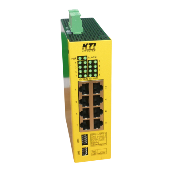
Page 7: Product Panels
1.2 Product Panels The following figure illustrates the panels of the switch:... -
Page 8: Led Indicators
1.3 LED Indicators Function Power status ALARM Alarm relay status Port 1 – Port 8 1 - 8 1Gbps link and activity status (Port 1 - Port 8) 100/10 100Mbps or 10Mbps link and activity status (Port 1 - Port 8) 1.4 Specifications 10/100/1000 Twisted-pair Copper Port (UTP, RJ-45) Compliance... - Page 9 Alarm Relay Output Screwed terminal block 3 dry contacts (NC pair & NO pair) Contact rating 30VDC/1A or 120VAC/0.5A Alarm events Power failure, configured port link faults Mechanical Dimension (base) 42 x 106 x 140 mm (WxDxH) Housing Enclosed metal with no fan Mounting Din-rail mounting Panel mounting (optional)
-
Page 10: Installation
2. Installation 2.1 Unpacking The product package contains: The switch unit for Din-rail mounting One product CD-ROM 2.2 Safety Cautions To reduce the risk of bodily injury, electrical shock, fire and damage to the product, observe the following precautions. -
Page 11: Mounting The Switch To A Din-Rail
2.3 Mounting the Switch to a Din-Rail In the product package, a DIN-rail bracket is provided or has been installed for mounting the switch in a industrial DIN-rail enclosure. The steps to mount the switch onto a DIN rail are: 1. - Page 12 3. Clamp the unit to the DIN rail and make sure it is mounted securely. The final dimension is: -12-...
-
Page 13: Mounting The Switch On A Panel
2.4 Mounting the Switch on a Panel The switches may be provided optionally with a panel mounting bracket. The bracket supports mounting the switch on a plane surface securely. The mounting steps are: 1. Install the mounting bracket on the switch unit. 2. - Page 14 3. Screw the switch unit on a panel and the locations for screws are shown below: -14-...
-
Page 15: Applying Power
2.5 Applying Power Power pins of the terminal block connector DC+ Positive ( ) input terminal DC- Negative ( ) input terminal NC, Reserved DC+/- Input specifications Working voltage range: +8V ~ +57VDC WARNING: The -48VDC power supply is not supported. Terminal Plug &... -
Page 16: Alarm Relay Output
2.6 Alarm Relay Output Alarm relay output is provided for reporting failure events to a remote alarm relay monitoring system. The replay output is provided with three contacts (supporting two logic types) on the terminal block connector next DC power interfaces. Alarm Relay output pins and logic: Alarm relay output, NO (Normal Open) contacts Open: normal, Shorted: Alarm... -
Page 17: Setting Dip Switches
2.7 Setting DIP Switches Functions of SW1 & SW2: SW1-1 ON to enable Port 1 link fault relay alarm SW1-2 ON to enable Port 2 link fault relay alarm SW1-3 ON to enable Port 3 link fault relay alarm SW1-4 ON to enable Port 4 link fault relay alarm SW1-5 ON to enable Port 5 link fault relay alarm... -
Page 18: Making Lan Connections
3. Making LAN Connections 3.1 10/100/1000 Copper Ports The 10/100/1000 RJ-45 copper ports support the following connection types and distances: Network Cables 10BASE-T: 2-pair UTP Cat. 3, 4, 5 , EIA/TIA-568B 100-ohm 100BASE-TX: 2-pair UTP Cat. 5, EIA/TIA-568B 100-ohm 1000BASE-T: 4-pair UTP Cat. -
Page 19: Led Indication
3.2 LED Indication Function State Interpretation Power status The power is supplied to the switch. The power is not supplied to the switch. ALARM Alarm status Alarm event occurs. No alarm event. Port 1Gbps link status A 1Gbps (1000Mbps) link is established on the port. (No traffic) BLINK Port link is up and there is traffic.
Need help?
Do you have a question about the KGS-0840 and is the answer not in the manual?
Questions and answers