Advertisement
Table of Contents
Advertisement
Table of Contents

Summary of Contents for JRC JFE-582
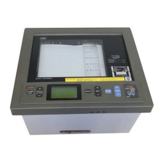
- Page 1 JFE-582 Echo Sounder INSTRUCTION MANUAL...
- Page 3 General Information Thank you for purchasing the Japan Radio Co., Ltd. JFE-582 Echo-Sounder. The JFE-582 conforms to the IMO (International Maritime Organization) performance standards, enabling sea floor displays and depth displays. ¡Before attempting to poerate this equipment, read this instruction manual thoroughly to ensure correct and safe operation in accordance with the warning instructions and operation procedures.
- Page 4 ii General Information...
-
Page 5: Before You Begin
Before You Begin Symbols Used In This Manual To ensure that the equipment is used safely and correctly, and that the operator and third parties are not exposed to danger or damage, pictograms are used in this manual and on the equipment itself. These pictograms are described below. -
Page 6: Usage Hints
Usage Hints WARNING Except when adjusting the Recording belt, do not open the recording mechanism of this equipment. There is a risk of electric shock if you touch the high voltage conductors. Except when replacing the recording pens, do not open the power supply rail cover. - Page 7 If you notice smoke, unusual smells, or abnormal heat coming from the equipment, immediately turn off the power switch, then contact JRC or its agent. There is a risk of fire, electric shock, or damage if you continue to use the equipment.
- Page 8 CAUTION Please contact JRC or its agent for the electrical installation of this equipment. Electrical installations carried out by other than the qualified staff may result in faulty operation. Do not store or operate the equipment where subject to temperatures in excess of 55℃. High temperature may cause failures.
- Page 9 CAUTION Do not turn on the equipment's power when the ship is in dry docks. Failure to observe this caution may result in damage to the transducer, etc. For safety when the equipment is to be left unused for an extended period, turn off the power switch. Do not use thinners, benzene, or other organic solvents to clean the equipment, as doing so will damage the surfaces.
-
Page 10: External View
External View viii External View... -
Page 11: Table Of Contents
Contents General Information ......................i Before You Begin ......................iii Usage Hints ........................iv External View ........................viii Explanation of Terms ......................x 1. Introduction ........................1 1.1 Function ..........................1 1.2 Feature ..........................1 1.3 Components .......................... 2 1.4 Construction .......................... 3 1.5 System Configuration ...................... -
Page 12: Explanation Of Terms
Explanation of Terms NMEA0183 : NMEA stands for the National Marine Electronics Association. NMEA0183 is the format used when sending or receiving depth, position, water temperature, ship speed and other information between marine equipment. Bubbling : The phenomenon where the image of the seabed is interrupted due to air bubbles caused by the ship's hull or the propeller during a voyage. -
Page 13: Introduction
1. Introduction 1.1 Function The JFE-582 Echo-Sounder consists of a transducer mounted on the bottom of the ship's hull and a main unit that displays information on the depth and formation of the sea bottom. This information is gained by using ultrasonic waves sent from the transducer that are then reflected off the sea bottom and picked up again by the transducer. -
Page 14: Components
1.3 Components This section lists components and optional equipment. Standard Equipment Name Type No. Qty. Remarks Recorder JFE-582 Matching box AW-154F Transducer mounting NKF-341 Cable length: 20m Spare unit 7ZXBS0010 Instruction manual 7ZPBS2301B Optional Equipment Name Type No. Qty. Remarks... -
Page 15: Construction
1.4 Construction Equipment Outline The following shows the external dimensions of the JFE-582. 1. External dimensions of JFE-582 recorder (Unit: mm) Mass: 11kg 2. Dimensions of AW-154F Matching box φ9 Mounting hole (Unit: mm) Terminal board Mass: 4kg Wire through metal... - Page 16 External Dimensions of Transducer mounting The external dimensions illustrated below are for the standard equipment. Please refer to the separately supplied drawings if your specifications are not standard. 1. NKF-341 (Installed on ship's bottom) Cabtire cable φ135 20m φ12.9 Flange JIS B 2222 (10K-32)...
-
Page 17: System Configuration
1.5 System Configuration AW-154F JFE-582 Matching box Recorder 660V-DPYCS-2.0 (Shipbuilding yard) AC100/110/115/ Depth data output 200/220/230V (NMEA0183/JRC format) (On-board power supply) DC24V Depth alarm output (On-board power supply) (relay contact) Power fail alarm output External navigation equipment (relay contact) (NMEA0183/0180/JRC format) -
Page 18: Names And Functions Of The Components
2. Names and Functions of the Components This section describes the names and functions of the control panel and its controls. DEPTH PWR FAIL PWR/PANEL ALARM DEPTH SELECT MARK RANGE ALARM Figure 2-1 Control Panel Name Function ① Power/Brightness Switches the equipment power on and off, adjusts the brightness of the panel and plotter illumination, and stops the buzzer from sounding in the event of a power fail alarm. -
Page 19: Installation
3. Installation CAUTION When installing the equipment, securely connect the earth lead to the earth terminal. Failure to connect the earth may result in electric shock in the event of a fault or power leak developing. Do not install or operate the equipment where subject to temperatures 55°C or higher or -15°C or lower. -
Page 20: Installing The Recorder Unit
3.1 Installing the Recorder Unit Flush-Mounted Equipment Figure 3-1 3. Installation...


Need help?
Do you have a question about the JFE-582 and is the answer not in the manual?
Questions and answers
HOW TO STOP PRINTING RECORDING PAPER AND ROTATING RECORDING PEN
To stop printing on the JRC JFE-582 recording paper and stop the recording pen from rotating, turn off the main power switch on the power supply unit and ensure the front panel switch is off.
This answer is automatically generated