
Related Manuals for JRC JFC-7050


Summary of Contents for JRC JFC-7050
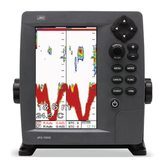
- Page 1 Echo Sounder/Fish Finder JFC-7050 - High resolution - high accuracy - Dual frequency(50/200KHz) - Fully automatic(gain, range, etc) - Alarm & A-scope - Fast and easy operation...
-
Page 2: Table Of Contents
TABLE OF CONTENTS Important Notice Echo sounder System Welcome Introduction Keypad How to use [ Power / Brightness ] Display Unit SPEC of the connectors Display Screen FF + Highway FF + Steering Operation Mode Gain Select Page Customize of screen Customize of data bar Navigation data edit Menu... - Page 3 5. Color 6. Pulse 7. Output Power 8. Alarm 9. Setup 0. Others Installation Display Unit Location Power Connection Sensor Connection Transducer Installation Transom Mounting Transom Transducer Maintenance Through-hull Transducers Dead-rise Through-hull Transducer Maintenance...
- Page 4 Pictorials This manual uses the following symbols for easy understanding safety instructions. Always follow these instructions carefully. WARNING Always follow this safety instruction to prevent death or injury. Follow this safety instruction to avoid possible injury or damage to your property.
- Page 5 Installation Cautions <For service Personnel> Follow installation instructions to avoid personal injury and system malfunction. Installation in Mount your JFC-7050 on a rigid frame or base to prevent your unit from rigid location. working loose. Use correct Use the installation materials provided in the standard accessory pack Installation only.
- Page 6 Operation Notes <For operators> Observe the following operation notes, otherwise the system failure or deterioration can result. And periodical inspection and maintenance are required for keeping the system in an optimum condition. The waypoint and other registered data may become unreadable by Backup important data.
- Page 7 - 4 -...
-
Page 8: Echo Sounder System
CAUTION The performance of LCD displays are degraded by continuous direct exposure to ultraviolet rays. Locate your JFC-7050 Display away from direct sunlight. When not in use. Keep the display covered. DISPLAY BREAKAGE WARNING The LCD display module contains a liquid. If the display is broken and the liquid contacts your skin, wash it off immediately in running water for 15 minutes. - Page 9 - 6 -...
-
Page 10: Introduction
The JFC-7050 is a premium multifunction command and control center. JFC-7050 front panel keyboard and its wide screen with wide viewing area make placement easy. Although JFC-7050 offers many advanced features, operation is simplified through the use of popup menus similar to those found on personal computers. - Page 11 Echo sounder System Option Transducer Model Name Airmar Part No. JRC Code B45 TRANSDUCER 31-272-14-01 5AWBF00001 P58 TRANSDUCER 31-498-3-01 5AWBF00002 P319 TRANSDUCER 31-323-14-01 5AWBF00003 B60-20 TRANSDUCER 31-556-8-02 5AWBF00004 Type:B45 Thru-Hull(8pin-A Female) Depth+Temp TVR(50):155 RVR(50):-174 TVR(200):164 RVR(200):-184 Type:P58 Transom Mount(8pin-A Female) Depth+Temp+Speed...
-
Page 12: Keypad
Echo sounder System Keypad Description With MENU : Choosing the menu. [Cursor Without MENU : Choosing the frequency. Key] (50/200KHz) [GAIN/STC] Button : Enter when menu table on the screen. & Rotary : Adjustment of gain level with turning. [ENTER] Setting up the depth range, when depth range [+] &[-] sets “manual range”. -
Page 13: How To Use [Power/Brightness]
Echo sounder System How to use [Power/Brightness] Press [PWR/BRT] Use PWR: Press [PWR/BRT] shortly to turn on Power. To turn off the power, keep pressing the [BRT/PWR] until the end of counting. 2.Use BRT: Press [BRT/PWR] shortly and the brightness can be controlled. Use the arrow keys [←][→]of the cursor to control the brightness and the contrast. -
Page 14: Display Unit
Echo sounder System Display Unit <Front> 7 inch Color LCD Keypad Knob Mounting Bracket <Rear> Connector - 11 -... -
Page 15: Spec Of The Connectors
Echo sounder System SPEC of the connectors - 12 -... -
Page 16: Display
Display Screen High Frequency Low Frequency Depth bar Red color : It is selected to Data bar setup Frequency - 13 -... -
Page 17: Ff + Highway
Display FF + Highway The highway display provides a 3D view of own ship’s progress toward destination (waypoint). Destination waypoint name Bearing from own ship to destination Course Over waypoint Ground Destination Range from own waypoint ship to destination Speed Over waypoint Ground XTE Alarm Radius... -
Page 18: Ff + Steering
Display FF + Steering The steering display provides steering information such as ship’s speed, course, range, bearing, TTG. Bearing from own ship to destination waypoint Course Over Ground Bearing from own ship to Range from own destination ship to destination Cross-Track-Error Destination waypoint Time-To-Go to destination... -
Page 19: Operation
Operation Mode Echo sounder modes are selectable for single frequency or dual and some functions, for example bottom zoom or lock. Press [MODE] 1. Normal (200KHz or 50KHz) Normal mode (with Auto Range active) displays the sounder image with the surface at the top of the screen and the sea bottom in the lower part of the screen. -
Page 20: Gain
Operation 4. Normal (200KHz and 50KHz) The high frequency (200KHz) displays on the left and the low frequency (50KHz) Normal displays on the right, which increase the accuracy of a fish school and your decision to catch fishes. 5. Bottom Zoom (200KHz and 50KHz) The high frequency (200KHz) displays on the left and the low frequency (50KHz) Bottom Zoom displays on the right, which increase the accuracy of a fish school and your decision to catch fishes. -
Page 21: Select Page
Operation Select Page Select [Page] menu and then go to “Pages” screen Selectable Pages by red box and then press [ENTER] key. red box - 18 -... -
Page 22: Customize Of Screen
Operation Customize of screen Press [FUNC] key for 3 seconds on the Pages which selected red box.(*Refer Fig. 1.1.1 as below) Select the layout of the formation of screen.(*Refer Fig. 1.1.2 as below) Select displays .(*Refer Fig. 1.1.3 & 1.1.4 as below) <Fig. -
Page 23: Customize Of Data Bar
Operation Customize of data bar [MENU] -> Setup -> Customizing -> Databar -> Edit Select the section to edit by red box. .(*Refer Fig. 1.2.1 as below) Press [ENTER] key and select the data as a user want.(*Refer Fig. 1.2.2 as below) Finish the formation of data bar, press [CANCEL] key to complete. -
Page 24: Navigation Data Edit
Operation Navigation data edit [MENU]-> Setup->Customizing->Navigation Data->edit Select the section to edit .(*Refer Fig. 1.3.1 as below) Press [ENTER] key and select the data as a user want. .(*Refer Fig. 1.3.2 as below) Finish the formation of data bar, press [CANCEL] key to complete (* If no navigation data on present activated display, it is not available to edit) <Fig. -
Page 25: Menu
The menu and explanation of operation are displayed. Press [MENU] 1. Depth Range JFC-7050 selects the best condition for measuring the depth automatically in the environment of the sea. Or the user selects measuring the depth by Manual in the menu. The default setting is Auto.) 2. -
Page 26: Rejection
Operation 3.5.Depth 3.5.1. Display On/Off the depth range on the screen. The default setting is On.) 3.5.2. Font Size Select the depth range font size on the screen. The default setting is Large.) 3.6.TEMP 3.6.1. Display On/Off the temperature on the screen. ( The default setting is Off.) 3.6.2. -
Page 27: Color
Operation 4.2. Noise Rejection Your Echo sounder could be disturbed by the engine noise. This function can reject the noise from the engine or other machinery instruments. The default setting is Off.) 5. Color 5.1. Bottom Color Level This function adjusts the colors. Make it upper level, the color becomes darker. The default setting is Off.) 5.2. - Page 28 Operation 8.1.2. Deep Range Setup the range of deep depth alarm The default setting is 0m.) 8.1.3. Shallow Alarm It alarms when the set shallow depth is out of the range. The default setting is Off.) 8.1.4. Shallow Range Setup the range of shallow depth alarm The default setting is 0m.) 8.2.
-
Page 29: Setup
Operation 8.3.3.Alarm Range If the alram is on, It is available to setup the Range(hight) of the Fish-school.(The bar, next of display is shown) The default setting is 50m.) 8.3.4. Alarm Interval If the alram is on, It is available to setup the alarm interval. The default setting is Middle) 8.3.5. - Page 30 (☞ The default setting is MM-DD-YY.) 9.3.4. Month Format Setup the character of month(Ex: 1, 2, 3…or JAN, FEB, MAR…) (☞ The default setting is Character.) 9.4. Input/Output 9.4.1. Output Sentence The JFC-7050 allows customizing the NMEA.0183 sentence. NMEA Description Default $GPDBT Depth below transducer...
- Page 31 Operation * Input sentence The JFC-7050 accepts NMEA 0183 sentences NMEA Description $GPRMC Recommended minimum specific GNSS data $GPGGA Global positioning system fix data $GPVTG Course over ground and ground speed $GPZDA Time and date 9.5. Speed Source Switch the Sensor/NMEA.
- Page 32 Operation 9.8. Buzzer It is can be sound on/off. (☞ The default setting is On.) 9.9. Simulator It is necessary for an indoor demonstration. The simulations of Fish finder in the memory.. 9.10. Customizing 9.10.1. Databar 9.10.1.1. Position Setting up up/down the position of databar on the display. (☞...
-
Page 33: Others
Operation 10. Others 10.1. Key setup It is available to set up [FUNC] key and [EVENT] key on the JFC-7050. 10.1.1. [FUNC] key: Set the function frequently used for your convenience. The default setting is Page.) [FUNC]KEY SETUP 1.Page 2.Image Speed 3.Color Rejection... - Page 34 Marked [● REC] in red color on the upper right on the data bar during recording. Note: The recording file is stored in external memory cards, SD memory. Check SD memory in the JFC-7050. (* Recording time is different by the size of the memory card) 10.4.
- Page 35 Operation 10.6. Capture List Available to display and delete the capture file 10.7. Active Select the activated section. 10.8. Page Select the configuration & modification you wish. - 32 -...
-
Page 36: Vrm
Operation Press [VRM] The VRM (movable marker) shown by the green line can be moved up and down. It is convenient to measure the depth by aligning with the target such as school of fish. * Caution: When several seconds pass after finishing the VRM operation, the numerical of marker depth becomes normal display. - Page 37 - 34 -...
-
Page 38: Installation
Installation Display unit brings expandable display technology to your bridge or navigation station. A careful installation will assure maximum benefit from Display unit integrated features. Display Unit Location Select a location for your Display unit that provides easy viewing from all likely operator’s positions. The display unit is designed to be mounted on either a console or from an overhead surface. -
Page 39: Power Connection
Installation Drill a 1/4 in. diameter hole at each marked location. Mount the Display unit bracket using bolts through the mounting surface. Place large flat washers on the opposite side of the mounting surface from the bracket and then install lock washers and nuts. Tighten securely. Install the display unit into the mounting bracket. -
Page 40: Transducer Installation
An input designation means, in put to Echo sounder unit and an output designation means, output from JFC-7050. Sensors will have similar designations, but from the sensors point of view. Therefore, a sensor output will connect to an JFC-7050 input and a sensor input will connect to an Echo sounder unit output. -
Page 41: Transom Mounting
For boats with poor water flow under the transom or on in-boards, consider selecting a through-hull transducer. JRC offers many styles of transducers. Determine the transducer mounting place by referring to the steps mentioned above. For best result, the transducer face should be level. -
Page 42: Through-Hull Transducers
Through-hull transducers are recommended for in-boards and other vessels with disturbed water flow under the transom. JRC offers several models of bronze through-hull transducers. To enjoy the full capability of your Sonar, select a dual frequency model with temperature sensor. Sturdy bronze construction assures a secure installation and provides a strong base for fairing blocks, if needed, to compensate for hull shape. -
Page 43: Dead-Rise
Installation Dead-rise On hulls with dead-rise of 5 or less, the transducer may be mounted directly through the hull. Where dead-rise is greater than 5, fairing blocks must be used to orient the face of the transducer parallel with the water surface. In this case, no fairing block is necessary. -
Page 44: Through-Hull Transducer Maintenance
Installation Through-hull Transducer Maintenance If your boat is kept in the water, performance of your JFC-7050 Sonar will be adversely affected by accumulations of sea growth on the face of the transducer. To prevent sea growth effects, the face of the transducer may be coated with antifouling paint specially formulated for transducers. - Page 45 - 42 -...
- Page 46 - 43 -...
- Page 47 - 44 -...
- Page 48 Fax: +81 3 3779 1420 Guarantee for One Year Above agent or dealer warrants the produced Echo Sounder, JFC-7050 for One (1) year for guarantee as bellows. 1.Main Unit : One (1) year guarantee after a user purchases the product within one (1) year 2.
- Page 49 CODE No.72ZPNA2231 18-7, Osaki 1-chome, Shinagawa-kuTokyo 141-0032 Japan Email: marine-international@jrc.co.jp Fax: +81 3 3779 1420...
Need help?
Do you have a question about the JFC-7050 and is the answer not in the manual?
Questions and answers