Konica Minolta BizHub C360 Service Manual
Hide thumbs
Also See for BizHub C360:
- Service manual (1150 pages) ,
- User manual (402 pages) ,
- Installation manual (25 pages)
Table of Contents
Advertisement
Quick Links
Advertisement
Chapters
Table of Contents

Related Manuals for Konica Minolta BizHub C360


Summary of Contents for Konica Minolta BizHub C360
-
Page 1: Service Manual
SERVICE MANUAL THEORY OF OPERATION 2009.07 Ver. 1.0... -
Page 2: Table Of Contents
WARNING INDICATIONS ON THE MACHINE ............S-18 MEASURES TO TAKE IN CASE OF AN ACCIDENT ............S-20 Composition of the service manual ................. C-1 Notation of the service manual ..................C-2 bizhub C360/C280/C220 Main body OUTLINE ........................1 CONFIGURATION/OPERATION .................. 15 DF-617 OUTLINE ........................ - Page 3 SD-509 OUTLINE ........................1 CONFIGURATION/OPERATION ..................3 JS-603 OUTLINE ........................1 CONFIGURATION/OPERATION ..................3 FS-529 OUTLINE ........................1 CONFIGURATION/OPERATION ..................5 EK-604/605/SC-507 EK-604..........................1 EK-605..........................2 SC-507 ........................... 4...
-
Page 4: Safety And Important Warning Items
IMPORTANT NOTICE Because of possible hazards to an inexperienced person servicing this product as well as the risk of damage to the product, KONICA MINOLTA BUSINESS TECHNOLOGIES, INC. (hereafter called the KMBT) strongly recommends that all servicing be performed only by KMBT-trained service technicians. -
Page 5: Safety Warnings
[1] MODIFICATIONS NOT AUTHORIZED BY KONICA MINOLTA BUSINESS TECHNOLOGIES, INC. KONICA MINOLTA brand products are renowned for their high reliability. This reliability is achieved through high-quality design and a solid service network. Product design is a highly complicated and delicate process where numerous mechanical, physical, and electrical aspects have to be taken into consideration, with the aim of arriving at proper tolerances and safety factors. - Page 6 SAFETY AND IMPORTANT WARNING ITEMS [2] POWER PLUG SELECTION In some countries or areas, the power plug provided with the product may not fit wall outlet used in the area. In that case, it is obligation of customer engineer (hereafter called the CE) to attach appropriate power plug or power cord set in order to connect the product to the supply.
-
Page 7: Checkpoints When Performing On-Site Service
SAFETY AND IMPORTANT WARNING ITEMS [3] CHECKPOINTS WHEN PERFORMING ON-SITE SERVICE KONICA MINOLTA brand products are extensively tested before shipping, to ensure that all applicable safety standards are met, in order to protect the customer and customer engi- neer (hereafter called the CE) from the risk of injury. However, in daily use, any electrical equipment may be subject to parts wear and eventual failure. - Page 8 SAFETY AND IMPORTANT WARNING ITEMS Power Plug and Cord WARNING • When using the power cord set (inlet type) that came with this product, make sure the connector is securely inserted in the inlet of the product. When securing measure is provided, secure the cord with the fixture properly.
- Page 9 SAFETY AND IMPORTANT WARNING ITEMS Wiring WARNING • Never use multi-plug adapters to plug multiple power cords in the same outlet. If used, the risk of fire exists. • When an extension cord is required, use a specified one. Current that can flow in the extension cord is limited, so using a too long extension cord may result in fire.
- Page 10 SAFETY AND IMPORTANT WARNING ITEMS Ventilation CAUTION • The product generates ozone gas during operation, but it will not be harmful to the human body. If a bad smell of ozone is present in the following cases, ventilate the room. a.
- Page 11 SAFETY AND IMPORTANT WARNING ITEMS Work Performed with the Product Powered On WARNING • Take every care when making adjustments or performing an operation check with the product powered. If you make adjustments or perform an operation check with the external cover detached, you may touch live or high-voltage parts or you may be caught in moving gears or the timing belt, leading to a risk of injury.
- Page 12 SAFETY AND IMPORTANT WARNING ITEMS Safety Checkpoints WARNING • Check electrode units such as a charging corona unit for deterioration and sign of leakage. Current can leak, leading to a risk of trouble or fire. • Before disassembling or adjusting the write unit (P/H unit) incorporating a laser, make sure that the power cord has been disconnected.
-
Page 13: Handling Of Consumables
SAFETY AND IMPORTANT WARNING ITEMS Safety Checkpoints WARNING • Make sure that all screws, components, wiring, connec- tors, etc. that were removed for safety check and mainte- nance have been reinstalled in the original location. (Pay special attention to forgotten connectors, pinched cables, forgotten screws, etc.) A risk of product trouble, electric shock, and fire exists. - Page 14 SAFETY AND IMPORTANT WARNING ITEMS Handling of Service Materials CAUTION • Use only a small amount of cleaner at a time and take care not to spill any liquid. If this happens, immediately wipe it off. A risk of fire exists. •...
- Page 15 SAFETY AND IMPORTANT WARNING ITEMS [4] Used Batteries Precautions ALL Areas CAUTION Danger of explosion if battery is incorrectly replaced. Replace only with the same or equivalent type recommended by the manufacturer. Dispose of used batteries according to the manufacturer’s instructions. Germany VORSICHT! Explosionsgefahr bei unsachgemäßem Austausch der Batterie.
-
Page 16: Internal Laser Radiation
Internal Laser Radiation semiconductor laser Maximum power of the laser diode 15 mW bizhub C360/C280 8.0 µW Maximum average radiation power (*) bizhub C220 5.3 µW Wavelength... - Page 17 SAFETY AND IMPORTANT WARNING ITEMS U.S.A., Canada (CDRH Regulation) • This machine is certified as a Class 1 Laser product under Radiation Performance Stan- dard according to the Food, Drug and Cosmetic Act of 1990. Compliance is mandatory for Laser products marketed in the United States and is reported to the Center for Devices and Radiological Health (CDRH) of the U.S.
- Page 18 SAFETY AND IMPORTANT WARNING ITEMS Finland, Sweden LUOKAN 1 LASERLAITE KLASS 1 LASER APPARAT VAROITUS! • Laitteen käyttäminen muulla kuin tässä käyttöohjeessa mainitulla tavalla saat- taa altistaa käyttäjän turvallisuusluokan 1 ylittävälle näkymättömälle laser- säteilylle. puolijohdelaser Laserdiodin suurin teho 15 mW aallonpituus 770-800 nm VARNING!
-
Page 19: Laser Safety Label
SAFETY AND IMPORTANT WARNING ITEMS Laser Safety Label • A laser safety label is attached to the inside of the machine as shown below. * Only for the U.S.A. A0EDP0E505DA Laser Caution Label • A laser caution label is attached to the outside of the machine as shown below. A0EDP0C503DA S-16... -
Page 20: Precautions For Handling The Laser Equipment
SAFETY AND IMPORTANT WARNING ITEMS PRECAUTIONS FOR HANDLING THE LASER EQUIPMENT • When laser protective goggles are to be used, select ones with a lens conforming to the above specifications. • When a disassembly job needs to be performed in the laser beam path, such as when working around the printerhead and PC drum, be sure first to turn the printer OFF. -
Page 21: Warning Indications On The Machine
SAFETY AND IMPORTANT WARNING ITEMS WARNING INDICATIONS ON THE MACHINE Caution labels shown are attached in some areas on/in the machine. When accessing these areas for maintenance, repair, or adjustment, special care should be taken to avoid burns and electric shock. CAUTION It is illegal to copy certain types of documents. - Page 22 SAFETY AND IMPORTANT WARNING ITEMS High voltage This area generates high voltage. Be careful not to touch here when the power is turned ON to avoid getting an electric shock. High voltage This area generates high voltage. Be careful not to touch here when the power is turned ON to avoid getting an electric shock.
-
Page 23: Measures To Take In Case Of An Accident
MEASURES TO TAKE IN CASE OF AN ACCIDENT MEASURES TO TAKE IN CASE OF AN ACCIDENT 1. If an accident has occurred, the distributor who has been notified first must immediately take emergency measures to provide relief to affected persons and to prevent further damage. -
Page 24: Composition Of The Service Manual
Composition of the service manual This service manual consists of Theory of Operation section and Field Service section to explain the main machine and its corresponding options. Theory of Operation section gives, as information for the CE to get a full understanding of the product, a rough outline of the object and role of each function, the relationship between the electrical system and the mechanical system, and the timing of operation of each part. -
Page 25: Notation Of The Service Manual
Notation of the service manual A. Product name In this manual, each of the products is described as follows: (1) bizhub C360/C280/C220: Main body (2) Microsoft Windows 98: Windows 98 Microsoft Windows Me: Windows Me Microsoft Windows NT 4.0: Windows NT 4.0 or Windows NT... - Page 26 SERVICE MANUAL THEORY OF OPERATION 2009.07 Ver. 1.0...
-
Page 27: Revision History
Revision history After publication of this service manual, the parts and mechanism may be subject to change for improvement of their performance. Therefore, the descriptions given in this service manual may not coincide with the actual machine. When any change has been made to the descriptions in the service manual, a revised version will be issued with a revision mark added as required. - Page 28 Theory of Operation Ver. 1.0 Jul. 2009 CONTENTS bizhub C360/C280/C220 Main body OUTLINE SYSTEM CONFIGURATION................... 1 PRODUCT SPECIFICATIONS ................3 Type ........................3 Functions ......................4 Paper ........................6 Materials ....................... 7 Print volume......................8 Machine specifications..................9 Operating environment ..................9 Print functions .......................
- Page 29 Theory of Operation Ver. 1.0 Jul. 2009 WRITE SECTION (PH SECTION) ................ 34 Configuration ...................... 34 Operation......................35 9.2.1 Outline ......................35 9.2.2 Laser exposure process................36 9.2.3 Laser emission timing ................. 37 9.2.4 Laser emission stop..................38 9.2.5 Laser emission area ................... 39 9.2.6 Color registration control (color shift correction) system......
- Page 30 Theory of Operation Ver. 1.0 Jul. 2009 11.3.4 Developing bias................... 79 11.3.5 Toner scattering prevention................. 81 11.3.6 Developing cooling ..................82 11.3.7 Toner density control ................... 83 11.3.8 Developing unit detection................84 11.3.9 Developing unit life detection ..............86 11.3.10 Number of field standard printed pages............87 TONER SUPPLY SECTION ..................
- Page 31 Theory of Operation Ver. 1.0 Jul. 2009 13.3.10 Transfer belt life detection ................. 127 2ND IMAGE TRANSFER SECTION ..............131 14.1 Configuration ....................131 14.2 Drive ......................... 132 14.3 Operation......................133 14.3.1 2nd image transfer control ................ 133 14.3.2 Control of toner application to 2nd image transfer roller ......134 14.3.3 2nd image transfer roller cleaning.............
- Page 32 Theory of Operation Ver. 1.0 Jul. 2009 17.2.1 Layout of sensors and rollers ..............173 17.3 Operation ......................174 17.3.1 Up/down control ..................174 17.3.2 Paper feed control ..................177 17.3.3 Paper size detection control..............189 17.3.4 Remaining paper detection control ............191 17.3.5 Paper feed tray locking mechanism ............
- Page 33 Theory of Operation Ver. 1.0 Jul. 2009 PAPER EXIT/SWITCHBACK SECTION ............. 230 21.1 Configuration ....................230 21.2 Drive ......................... 231 21.3 Operation......................232 21.3.1 Transport control ..................232 DUPLEX SECTION..................... 233 22.1 Configuration ....................233 22.2 Drive ......................... 234 22.3 Operation......................235 22.3.1 Paper transport control ................
-
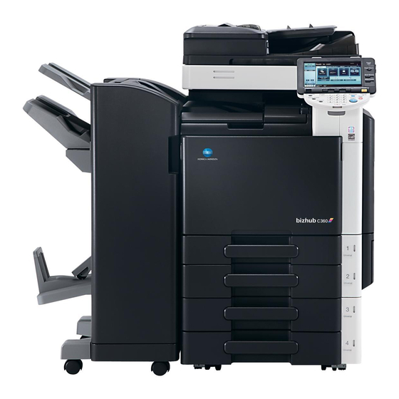
Page 34: Outline
[19] [22] [13] [18] [17] [16] [15] [14] A0EDF1E503DA [1] bizhub C360/C280/C220 [13] Mount kit MK-713 * Except for Europe area [2] Reverse automatic document feeder DF-617 [14] Desk DK-507 * Except for Europe area [3] Assist handle AH-101 [15] Paper feed cabinet... - Page 35 2/2 System rear view A0EDF1E504DA bizhub C360/C280/C220 Mount kit MK-720 Fax kit FK-502 Key counter kit KIT-1 Image controller IC-412 i-Option LK-101 v2/102/103 v2/105 * bizhub C360/C280 only Security kit SC-507 Upgrade kit UK-203 Video interface kit VI-505 * bizhub C360/C280 only...
-
Page 36: Product Specifications
Theory of Operation Ver. 1.0 Jul. 2009 2. PRODUCT SPECIFICATIONS PRODUCT SPECIFICATIONS Type Type Desktop/console *1 scanner/printer Printing process Laser electrostatic printing system PC drum type OPC drum: KM-12 (OPC with high mold releasability) Scanning density 600 dpi Exposure lamp White rare-gas fluorescent lamp 30 W Platen Stationary (mirror scan) -
Page 37: Functions
Processing speed Plain paper bizhub C362/C280: 166.6 mm/s (black, full color), bizhub C220: 111.0 mm/s OHP film *2 Thick 1, Thick 2, bizhub C360/C280/C220: 55.5 mm/s Thick 3, Thick 4, Post card, Envelope, Label sheet Plain paper (glossy mode) Copying/printing... - Page 38 Theory of Operation Ver. 1.0 Jul. 2009 2. PRODUCT SPECIFICATIONS Fixed zoom ratios Full size x1.000 Reduction Metric area x0.500, x0.707, x0.816, x0.866 Inch area x0.500, x0.647, x0.733, x0.785 Enlargement Metric area x1.154, x1.224, x1.414, x2.000 Inch area x1.214, x1.294, x1.545, x2.000 Zoom ratios memory 3 memories ×0.250 to ×4.000...
-
Page 39: Paper
2. PRODUCT SPECIFICATIONS Theory of Operation Ver. 1.0 Jul. 2009 Paper Paper source (maximum tray capacity) Type Tray 1 Tray 2 Manual bypass tray ❍ (500 sheets) ❍ (500 sheets) ❍ (150 sheets) Plain paper (60 to 90 g/m / 16 to 24 lb) ⎯... -
Page 40: Materials
Theory of Operation Ver. 1.0 Jul. 2009 2. PRODUCT SPECIFICATIONS Materials Parts name Number of prints Type name Toner cartridge/C bizhub C360 26,000 prints *1 TN319C bizhub C280/C220 26,000 prints *1 TN216C Toner cartridge/M bizhub C360 26,000 prints *1 TN319M... -
Page 41: Print Volume
2. PRODUCT SPECIFICATIONS Theory of Operation Ver. 1.0 Jul. 2009 Print volume • bizhub C360 Average Color print 1,700 prints/month Black print 5,000 prints/month Maximum Color print 5,000 prints/month Black print 15,000 prints/month Average Color print 2,200 prints/month Black print... -
Page 42: Machine Specifications
Theory of Operation Ver. 1.0 Jul. 2009 2. PRODUCT SPECIFICATIONS Machine specifications Power requirements Voltage: AC 100 V, 120 V, 127 V, 220-240 V Current: 100 V 15 A 110 V 15 A 120 V 12 A 127 V 12 A 230 V 50/60 Hz ±... - Page 43 2. PRODUCT SPECIFICATIONS Theory of Operation Ver. 1.0 Jul. 2009 Supported computer IBM PC/AT compatible machine, Macintosh (PowerPC/Intel processor: Only MacOS X 10.4/10.5 for Intel processor) Printer driver PCL KONICAMINOLTA Windows NT Workstation Version 4.0 (SP6 or later) driver (PCL driver) Windows NT Server Version 4.0 (SP6 or later) Windows 2000 Professional (SP4 or later) Windows 2000 Server (SP3 or later)
- Page 44 Theory of Operation Ver. 1.0 Jul. 2009 2. PRODUCT SPECIFICATIONS Printer driver XPS KONICAMINOLTA Windows Vista Business * driver (XPS driver) Windows Vista Enterprise * Windows Vista Home Basic * Windows Vista Home Premium * Windows Vista Ultimate * Windows Server 2008 Standard * Windows Server 2008 Enterprise * * 32 bits (x86)/64 bits (x64) environment are supported...
-
Page 45: Scan Functions
2. PRODUCT SPECIFICATIONS Theory of Operation Ver. 1.0 Jul. 2009 Scan functions Scanner Scannable range Same as the copier (Max. 11 x 17: inch area, A3: metric area) Scan speed 70 pages/min (A4 or 8 1/2 x 11, Resolution 300 dpi) Functions Scan to E-mail, Scan to FTP, Scan to SMB, Scan to WebDAV, Scan to BOX... -
Page 46: Section Configuration
Theory of Operation Ver. 1.0 Jul. 2009 3. SECTION CONFIGURATION SECTION CONFIGURATION Scanner section (IR section) Paper exit/switchback section Fusing section Toner supply Duplex section section Image transfer section Write section Photo conductor (PH section) section Developing section Manual section Toner collecting section Paper feed section (Tray1) -
Page 47: Paper Path
4. PAPER PATH Theory of Operation Ver. 1.0 Jul. 2009 PAPER PATH A0EDT1C002DA... -
Page 48: Configuration/Operation
Theory of Operation Ver. 1.0 Jul. 2009 5. OVERALL CONFIGURATION CONFIGURATION/OPERATION OVERALL CONFIGURATION Control block diagram Scanner Inverter board Reverse section automatic document CCD board feeder Scanner R G B relay board Control panel Key counter Secret board R G B DC power supply unit Total USB board... -
Page 49: Image Creation Process
6. IMAGE CREATION PROCESS Theory of Operation Ver. 1.0 Jul. 2009 IMAGE CREATION PROCESS [13] Fusing [1] Photoelectric [15] Paper exit conversion [10] Transfer belt cleaning [9] Paper [7] 1st image transfer separation [2] Printer image processing [8] 2nd image transfer [3] Photo [14] Duplex... - Page 50 Theory of Operation Ver. 1.0 Jul. 2009 6. IMAGE CREATION PROCESS • A DC positive voltage is applied to the backside of the paper, thereby 2nd image transfer allowing the visible, developed image on the surface of the transfer belt to be transferred onto the paper. •...
-
Page 51: Image Forming Control
6. IMAGE CREATION PROCESS Theory of Operation Ver. 1.0 Jul. 2009 Image forming control Developing bias DC Y/M/C Developing bias DC K Main erase lamp Y/M/C Main erase lamp K Color PC motor (M2) Charge Y/M/C Charge K Color dev. unit engaged motor (M10) Developing clutch/K (CL6) Transfer belt retraction clutch (CL5) Image write start signal... -
Page 52: Interface Section
Theory of Operation Ver. 1.0 Jul. 2009 7. INTERFACE SECTION INTERFACE SECTION Configuration 7.1.1 Rear side Optional reverse automatic document feeder connector Optional finisher connector A0EDT2C504AA... -
Page 53: Right Side
7. INTERFACE SECTION Theory of Operation Ver. 1.0 Jul. 2009 7.1.2 Right side Front side Rear side (upper) Rear side (lower) A0EDT2C134DA... - Page 54 Theory of Operation Ver. 1.0 Jul. 2009 7. INTERFACE SECTION A. Front side Note • Use utmost care when unplugging or plugging the cable. If the USB cable extended from the USB port at the rear (upper) portion is unplugged, the USB port at the front side is no longer operational.
- Page 55 7. INTERFACE SECTION Theory of Operation Ver. 1.0 Jul. 2009 B. Rear side (upper) Notes • The USB cable is extended up to the USB port at the front side. If the cable is unplugged from the USB port, therefore, the USB port at the front side is no longer operational.
- Page 56 Theory of Operation Ver. 1.0 Jul. 2009 7. INTERFACE SECTION USB port cover USB cover sensor (PS47) A0EDT2C138DA • The USB cover sensor detects that the USB port cover is opened or closed.
- Page 57 7. INTERFACE SECTION Theory of Operation Ver. 1.0 Jul. 2009 C. Rear side (lower) Line extension kit (optional) Fax kit * The second line is (optional) on the outside. TEL terminal TEL terminal (optional) (optional) LINE terminal LINE terminal (optional) (optional) A0EDT2C139DA Fax kit (optional)
-
Page 58: Scanner Section
Theory of Operation Ver. 1.0 Jul. 2009 8. SCANNER SECTION SCANNER SECTION Configuration A0EDT2C141DA Inverter board (INVB) Scanner home sensor (PS201) Lens Scanner relay board (REYB/SCAN) CCD unit Exposure unit Mirror unit Scanner motor (M201) Status display board (MCMB) Angle sensor (PS202) Fax speaker (SP) Original size detection... -
Page 59: Drive
8. SCANNER SECTION Theory of Operation Ver. 1.0 Jul. 2009 Drive Scanner motor (M201) Scanner drive cable/R Scanner home sensor (PS201) Scanner drive cable/F Exposure unit Mirror unit A0EDT2C144DA... -
Page 60: Operation
Theory of Operation Ver. 1.0 Jul. 2009 8. SCANNER SECTION Operation 8.3.1 When the power is ON 1. The exposure unit moves from the scanner standby position to the home position. 2. Exposure unit moves from the home position to the shading position (under the shading correction sheet) and stops (in scanning direction). -
Page 61: Control When The Start Key Is Pressed
8. SCANNER SECTION Theory of Operation Ver. 1.0 Jul. 2009 8.3.2 Control when the Start key is pressed A. Original scanning mode Original scanning mode has two types: Original cover mode and DF mode. (1) Original cover mode 1. Turning the Start key ON will turn the exposure lamp ON (at the standby position). 2. - Page 62 Theory of Operation Ver. 1.0 Jul. 2009 8. SCANNER SECTION (2) DF mode • The original fed by the document feeder will be read at the original DF glass for. The exposure unit will move to the reading position and stops. The document will be read as the paper is transferred.
-
Page 63: Original Scanning Area
8. SCANNER SECTION Theory of Operation Ver. 1.0 Jul. 2009 8.3.3 Original scanning area Original scanning areas vary depending on a scanning mode. A. Original cover mode • Main scanning direction: Max. 297.0 mm • Sub scanning direction: Max. 431.8 mm B. -
Page 64: Original Size Detection Control
Theory of Operation Ver. 1.0 Jul. 2009 8. SCANNER SECTION 8.3.4 Original size detection control A. Detection method • For detection of the original size, the reflective size sensors detect the length of the orig- inal while the CCD detects the width of the original. Automatic document feeder or Original cover Angle sensor (PS202) 346.1 mm... - Page 65 8. SCANNER SECTION Theory of Operation Ver. 1.0 Jul. 2009 B. Original size judgement NOTE • Table 1 or 2 can be selected in the service mode. Criterion Metric area & china areas Table 1 Original Main scanning width (mm) size detection 0~130.0...
-
Page 66: Image Processing
Theory of Operation Ver. 1.0 Jul. 2009 8. SCANNER SECTION C. Detection timing Validates the original length Validates the original size Original size detection sensor/1 (PS204) Angle sensor (PS202) Exposure lamp (FL201) Original cover sensor (RS201) A00JT2C004AA 8.3.5 Image processing The image processing has following items. -
Page 67: Write Section (Ph Section)
9. WRITE SECTION (PH SECTION) Theory of Operation Ver. 1.0 Jul. 2009 WRITE SECTION (PH SECTION) Configuration PH unit A0EDT2C282DA Index mirror Index lens Index board (INDEXB) Cylindrical lens G3 lens Return mirror (light source) Synthetic mirror (Y,M,C) Laser drive board/C (LASDB/C) Laser drive board/M (LASDB/M) -
Page 68: Operation
Theory of Operation Ver. 1.0 Jul. 2009 9. WRITE SECTION (PH SECTION) Operation 9.2.1 Outline • The surface of the photo conductor is irradiated with a laser light and an electrostatic latent image is thereby formed. • The PH unit has a single-piece configuration. A semiconductor laser is provided for each of four different colors. -
Page 69: Laser Exposure Process
9. WRITE SECTION (PH SECTION) Theory of Operation Ver. 1.0 Jul. 2009 9.2.2 Laser exposure process A. Operation 1. The K laser light enters the cylindrical lens via the return mirror (light source). The Y, M, and C laser light enter the cylindrical lens via the synthetic mirror and return mirror (light source). -
Page 70: Laser Emission Timing
Theory of Operation Ver. 1.0 Jul. 2009 9. WRITE SECTION (PH SECTION) 9.2.3 Laser emission timing • After a print cycle has been started, when the stable rotation signals of photo conductor and polygon motor are detected, a laser ON signal is output from the printer control board. -
Page 71: Laser Emission Stop
9. WRITE SECTION (PH SECTION) Theory of Operation Ver. 1.0 Jul. 2009 9.2.4 Laser emission stop Emission of the laser beam is stopped if any of the following conditions is encountered dur- ing printing: • End of a print job •... -
Page 72: Laser Emission Area
Theory of Operation Ver. 1.0 Jul. 2009 9. WRITE SECTION (PH SECTION) 9.2.5 Laser emission area A. Main scanning direction • The print start position in the main scanning direction is determined by the main scan- ning print start signal (/HSYNC) that is output from the printer control board and the width of the paper. -
Page 73: Color Registration Control (Color Shift Correction) System
9. WRITE SECTION (PH SECTION) Theory of Operation Ver. 1.0 Jul. 2009 9.2.6 Color registration control (color shift correction) system A. Overview of the registration control • In a tandem engine, each four different color has an independent image reproduction process. - Page 74 Theory of Operation Ver. 1.0 Jul. 2009 9. WRITE SECTION (PH SECTION) B. Types of color shift • Color shift is misalignment of the images of three different colors, yellow (Y), magenta (M), and cyan (C), with respect to the image of black (K). •...
- Page 75 9. WRITE SECTION (PH SECTION) Theory of Operation Ver. 1.0 Jul. 2009 D. Correction of color shift due to overall scaling error in the main scan direction • If the image of each color (Y, M, C) and the image of black (K) vary in length in the main scan direction, changing the clock frequency of the laser diode can correct the length dif- ference in the main scan direction.
- Page 76 Theory of Operation Ver. 1.0 Jul. 2009 9. WRITE SECTION (PH SECTION) F. Skew (image skew) • If the image of each color (Y, M, C) is tilted against the image of black (K) in the sub- scanning direction, the image skew can be corrected by tilting the G3 lens of the print head unit.
-
Page 77: Color Skew Correction Control
9. WRITE SECTION (PH SECTION) Theory of Operation Ver. 1.0 Jul. 2009 9.2.7 Color skew correction control • Temperature may change inside the print head unit and the components can change over time. This may cause color skew problems. To prevent the problems, individual G3 lenses that correspond to Y, M, and C respectively have a color skew auto adjustment mechanism. - Page 78 Theory of Operation Ver. 1.0 Jul. 2009 9. WRITE SECTION (PH SECTION) A. Skew adjustment method • The following describe the direction in which the beam moves when the skew correction motor/Y, M, C is rotated in the clockwise direction. •...
-
Page 79: Skew Adjustment/Skew Adjustment Reset
9. WRITE SECTION (PH SECTION) Theory of Operation Ver. 1.0 Jul. 2009 9.2.8 Skew adjustment/skew adjustment reset • Certain specific conditions require that a skew adjustment be performed manually. There may also be cases where the “color skew correction control” cannot be executed for some reason. -
Page 80: Ph Window Cleaning
Theory of Operation Ver. 1.0 Jul. 2009 9. WRITE SECTION (PH SECTION) 9.2.10 PH window cleaning • The PH window, if contaminated, blocks the path of the laser beam and the surface of the photo conductor can no longer be exposed properly. This could result in image problems, including white bands or white lines on the print image. -
Page 81: Image Processing
9. WRITE SECTION (PH SECTION) Theory of Operation Ver. 1.0 Jul. 2009 9.2.11 Image processing The following image processing procedures relating to the write section are available. For details, see “24. IMAGE PROCESSING”. See P.249 Write section image processing block diagram •... -
Page 82: Photo Conductor Section
Theory of Operation Ver. 1.0 Jul. 2009 10. PHOTO CONDUCTOR SECTION 10. PHOTO CONDUCTOR SECTION 10.1 Configuration Erase lamp (mounted on the machine 1st image transfer roller frame side) Photo Transfer belt conductor Photo conductor Cleaning blade Developing unit Toner collecting screw Drum unit... -
Page 83: Drive
10. PHOTO CONDUCTOR SECTION Theory of Operation Ver. 1.0 Jul. 2009 10.2 Drive Color PC motor (M2) Transport motor (M1) Photo conductor/K Photo conductor/C Photo conductor/M Photo conductor/Y A0EDT2C010DA... -
Page 84: Operation
Theory of Operation Ver. 1.0 Jul. 2009 10. PHOTO CONDUCTOR SECTION 10.3 Operation 10.3.1 Photo conductor drive mechanism • Two independent photo conductor motors (for color and black) are used for the drive mechanism to suppress incorrect color registration and uneven pitch. A. - Page 85 10. PHOTO CONDUCTOR SECTION Theory of Operation Ver. 1.0 Jul. 2009 B. Photo conductor/Y, M, C drive mechanism • The photo conductors/Y, M, C are driven by the color PC motor. • Drive is transmitted to each of the photo conductors when the triangular-prism-shaped shaft is engaged with the mating coupling part.
-
Page 86: Photo Conductor Phase Control
Theory of Operation Ver. 1.0 Jul. 2009 10. PHOTO CONDUCTOR SECTION 10.3.2 Photo conductor phase control • The drive source of the photo conductor/K is the transport motor. The drive source of the color photo conductors/Y, M, C is the color PC motor. The three photo conductor drive gears/Y, M, C are connected by gears to each other and the photo conductors/Y, M, C is always in the same phase. -
Page 87: Photo Conductor Small Amount Rotation Control
10. PHOTO CONDUCTOR SECTION Theory of Operation Ver. 1.0 Jul. 2009 10.3.3 Photo conductor small amount rotation control • To prevent the same surface of the photo conductor from being left to stand for a long time, the photo conductor is rotated through a small amount so that its surface sensitivity can be kept uniform. -
Page 88: Erase Lamp Control
Theory of Operation Ver. 1.0 Jul. 2009 10. PHOTO CONDUCTOR SECTION 10.3.4 Erase lamp control • The toner image on the photo conductor is transferred to the transfer belt (1st image transfer). The potential left on the photo conductor after the toner image is transferred is neutral- ized by turning ON the erase lamp and any potential left on the surface of the photo con- ductor is neutralized. -
Page 89: Photo Conductor Cleaning
10. PHOTO CONDUCTOR SECTION Theory of Operation Ver. 1.0 Jul. 2009 10.3.5 Photo conductor cleaning • The toner image on the photo conductor is transferred to the transfer belt (1st image transfer). Part of the toner image that is not transferred is left on the surface of the photo conduc- tor. - Page 90 Theory of Operation Ver. 1.0 Jul. 2009 10. PHOTO CONDUCTOR SECTION B. Toner conveyance/collection mechanism • The toner collecting screw is rotated by the driving force transmitted from the photo con- ductor (The toner collecting screw rotates in time with the rotation of the photo conduc- tor.) •...
-
Page 91: Charge Corona Control
10. PHOTO CONDUCTOR SECTION Theory of Operation Ver. 1.0 Jul. 2009 10.3.6 Charge corona control • A high voltage DC negative charge is applied to the comb electrode and charge corona control plate (grid mesh) inside the charge corona. Charge discharged from the comb electrode causes the surface of the photo conductor to become uniformly charged via the charge corona control plate. -
Page 92: Charge Corona Cleaning
Theory of Operation Ver. 1.0 Jul. 2009 10. PHOTO CONDUCTOR SECTION B. Charge application end timing • Application of the charge to the comb electrode and charge corona control plate is termi- nated at timing when the surface of the photo conductor that faces the transfer belt as the 1st image transfer output (see the 1st image transfer section for more details) is turned OFF moves past the charge corona control plate (that is, the application of charge is ter- minated after effect on the surface of the photo conductor from the 1st image transfer is... -
Page 93: Ozone Filter
10. PHOTO CONDUCTOR SECTION Theory of Operation Ver. 1.0 Jul. 2009 10.3.8 Ozone filter • A high voltage DC negative charge is applied to the comb electrode and charge corona control plate (grid mesh) inside the charge corona. Charge discharged from the comb electrode causes the surface of the photo conductor to become uniformly charged via the charge corona control plate. -
Page 94: Drum Unit Detection
Theory of Operation Ver. 1.0 Jul. 2009 10. PHOTO CONDUCTOR SECTION D. Exhaust fan motor rotation time setting (Service Mode) • Rotation time of the exhaust fan motor can be adjusted to fall within the range of between 5 sec. and 15 min. using the Service Mode (default value 5 sec.). •... - Page 95 10. PHOTO CONDUCTOR SECTION Theory of Operation Ver. 1.0 Jul. 2009 A. Unit mounting detection • The drum unit new article detect board detects the mounting condition of the drum unit. • When a drum unit is detected in the mounted condition, control now proceeds to the “new article detection control”.
-
Page 96: Drum Unit Life Detection
Theory of Operation Ver. 1.0 Jul. 2009 10. PHOTO CONDUCTOR SECTION C. New article detection-disabled mode • The new article detection-disabled mode is used when a new drum unit is temporarily used for performing troubleshooting procedures of a machine. • No new article detection control is performed for the drum unit when the new article detection-disabled mode is used. - Page 97 10. PHOTO CONDUCTOR SECTION Theory of Operation Ver. 1.0 Jul. 2009 B. Drum rotation time counter life determination • Each of the printed counter and the drum rotation time counter has its own threshold value to determine its own life. If the drum rotation time counter value reaches the thresh- old, the machine determines that the drum unit has reached a new state.
- Page 98 Theory of Operation Ver. 1.0 Jul. 2009 10. PHOTO CONDUCTOR SECTION D. Drum unit life display • The life reaching screen appears when the count of the printed counter or the drum rota- tion time counter reaches the life threshold (print enabled, outside image guaranteed range).
- Page 99 10. PHOTO CONDUCTOR SECTION Theory of Operation Ver. 1.0 Jul. 2009 (1) Life reaching display (typical) A0EDT2E296DA (2) L code screen (typical) L code Target unit Drum unit C Drum unit M Drum unit Y Drum unit K Image transfer belt unit A0EDT2E297DA (3) Life stop display (typical) A0EDT2E298DA...
-
Page 100: Number Of Field Standard Printed
Theory of Operation Ver. 1.0 Jul. 2009 10. PHOTO CONDUCTOR SECTION 10.3.11 Number of field standard printed pages • The number of field standard printed pages is specified for this machine based on calcu- lation made by assuming field standard job modes as determined using the print volume and use conditions of the user. -
Page 101: Ozone Filter Life Detection
10. PHOTO CONDUCTOR SECTION Theory of Operation Ver. 1.0 Jul. 2009 10.3.13 Ozone filter life detection • The life counter of the ozone filter controls detection of life of the transfer belt (transport motor). • The counter value is recorded in the service EEPROM board of the machine. •... - Page 102 Theory of Operation Ver. 1.0 Jul. 2009 10. PHOTO CONDUCTOR SECTION B. Life display NOTE • The contents of the life warning display and life reaching display vary depending on the settings made in Consumable Life Reminder and Unit Change of the Service Mode and life stop of the security mode.
-
Page 103: Developing Section
11. DEVELOPING SECTION Theory of Operation Ver. 1.0 Jul. 2009 11. DEVELOPING SECTION 11.1 Configuration Doctor blade PC drum Developing roller Toner supply screw A0EDT2C033DA Color dev. unit engaged motor (M10) TCR sensor board Color PC motor (M2) Transport motor (M1) Developing clutch/K (CL6) TCR sensor board Developing roller/Y... -
Page 104: Drive
Theory of Operation Ver. 1.0 Jul. 2009 11. DEVELOPING SECTION 11.2 Drive A. Developing section/K drive mechanism • Drive force from the transport motor is transmitted to the developing clutch so that the developing section/K is driven. Transport motor (M1) Developing drive coupling Developing roller Developing clutch/K (CL6) - Page 105 11. DEVELOPING SECTION Theory of Operation Ver. 1.0 Jul. 2009 B. Developing section/Y, M, C drive mechanism • Drive force from the color PC motor is transmitted to the color dev. unit engaged gear so that the developing section/Y, M, C is driven. •...
- Page 106 Theory of Operation Ver. 1.0 Jul. 2009 11. DEVELOPING SECTION Color PC Color dev. unit engaged Coupling released motor (M2) motor (M10) Color dev. unit engaged gear Coupled Color drive transmis- sion gear Developing drive coupling A0EDT2C039DA...
- Page 107 11. DEVELOPING SECTION Theory of Operation Ver. 1.0 Jul. 2009 C. Color dev. unit engaged position detection • The color PC motor is the drive source of the developing section/Y, M, C. • When the color dev. unit engaged motor lets the coupling detection gear rotate, the color dev.
-
Page 108: Operation
Theory of Operation Ver. 1.0 Jul. 2009 11. DEVELOPING SECTION 11.3 Operation 11.3.1 Developing roller pressure mechanism • Generally, the Ds rollers are pressed up against the PC drum flanges, so that an opti- mum distance is maintained between the PC drum and the developing roller. (The Ds rollers are mounted coaxially with the developing roller and designed to be larger in diameter than the developing roller. -
Page 109: Developer Flow
11. DEVELOPING SECTION Theory of Operation Ver. 1.0 Jul. 2009 11.3.2 Developer flow 1. Toner replenished via the toner replenishing port located at the front side of the machine is fed to the toner supply screw/lower. It is then mixed with carrier by the toner supply screw/lower. - Page 110 Theory of Operation Ver. 1.0 Jul. 2009 11. DEVELOPING SECTION Doctor blade Developing roller Toner supply screw/upper Toner supply screw/lower A0EDT2C042DA Color developer circulation diagram A0EDT2C043DA Toner replenished Black developer circulation diagram (including carrier) Discharge port Developer being discharged A0EDT2C044DA...
-
Page 111: Auto Refining Developing System
11. DEVELOPING SECTION Theory of Operation Ver. 1.0 Jul. 2009 11.3.3 Auto refining developing system • Only the developing unit/K incorporates the auto refining developing system. • The toner cartridge/K is packed with both toner and carrier and the developing unit/K is replenished with fresh carrier at the same time that it is replenished with toner. -
Page 112: Developing Bias
Theory of Operation Ver. 1.0 Jul. 2009 11. DEVELOPING SECTION 11.3.4 Developing bias • The developing bias voltage (Vdc) is applied to the developing roller so that an adequate amount of toner is attracted onto the surface of the photo conductor. •... - Page 113 11. DEVELOPING SECTION Theory of Operation Ver. 1.0 Jul. 2009 A. Service Mode (1) Development AC Voltage Choice • The “Development AC Voltage” can be changed by changing the setting of “Imaging Pro- cess Adjustment/ Development AC Voltage Choice” of the Service Mode. This provides development performance that responds to various types of environment of the users.
-
Page 114: Toner Scattering Prevention
Theory of Operation Ver. 1.0 Jul. 2009 11. DEVELOPING SECTION 11.3.5 Toner scattering prevention • The toner scattering prevention plate and toner scattering prevention sheet are installed in an area around the developing roller, functioning to prevent toner from scattering. Toner scattering prevention plate Toner scattering... -
Page 115: Developing Cooling
11. DEVELOPING SECTION Theory of Operation Ver. 1.0 Jul. 2009 11.3.6 Developing cooling • The transfer belt cleaner cooling fan motor is provided to circulate air through the inside of the machine, so that the areas around the developing unit, drum unit, toner hopper, and the image transfer belt unit can be cooled. -
Page 116: Toner Density Control
Theory of Operation Ver. 1.0 Jul. 2009 11. DEVELOPING SECTION 11.3.7 Toner density control • The TCR sensor is mounted on the underside of each of the developing sections. The TCR sensor for C, M, Y and K is a non-contact magnetic type. Each of these sensors detects toner-to-carrier ratio (T/C) of the developer. -
Page 117: Developing Unit Detection
11. DEVELOPING SECTION Theory of Operation Ver. 1.0 Jul. 2009 11.3.8 Developing unit detection • The developing unit of each color of toner is provided with a TCR sensor board. The board detects different states of the corresponding developing unit. Life counter TCR sensor Image... - Page 118 Theory of Operation Ver. 1.0 Jul. 2009 11. DEVELOPING SECTION B. New article detection • The TCR sensor board detects whether the developing unit is new or not. (1) Detection timing • The new article detection control is performed if it is determined through the “unit mount- ing detection”...
-
Page 119: Developing Unit Life Detection
11. DEVELOPING SECTION Theory of Operation Ver. 1.0 Jul. 2009 11.3.9 Developing unit life detection • The life counter of the developing unit controls detection of life of the developing unit. • The life counter is available for the developing unit of each color. The counter value is recorded in the service EEPROM board of the machine. -
Page 120: Number Of Field Standard Printed
Theory of Operation Ver. 1.0 Jul. 2009 11. DEVELOPING SECTION B. Life display NOTES • The contents of the life warning display and life reaching display vary depending on the settings made in Consumable Life Reminder and Unit Change of the Ser- vice Mode and life stop of the security mode. -
Page 121: Toner Supply Section
12. TONER SUPPLY SECTION Theory of Operation Ver. 1.0 Jul. 2009 12. TONER SUPPLY SECTION 12.1 Configuration Toner cartridge A0EDT2C267DA Cooling fan motor/3 (FM2) Toner cartridge motor/CK (M7) Toner cartridge/K Toner supply motor/CK (M9) Toner cartridge motor/YM (M6) Toner cartridge/Y Toner near empty switch/K Toner cartridge/M (RS7) -
Page 122: Drive
Theory of Operation Ver. 1.0 Jul. 2009 12. TONER SUPPLY SECTION 12.2 Drive 12.2.1 Toner cartridge drive Toner cartridge motor/CK (M7) Toner cartridge motor/ YM (M6) Toner cartridge drive gear/K Toner cartridge drive gear/C Toner cartridge drive gear/M Toner cartridge drive gear/Y A0EDT2C178DA... -
Page 123: Toner Hopper Drive
12. TONER SUPPLY SECTION Theory of Operation Ver. 1.0 Jul. 2009 12.2.2 Toner hopper drive A. Toner conveying screw Toner supply motor/CK (M9) Toner conveying screw/K Toner conveying screw/C Toner conveying screw/M Toner conveying screw/Y Toner supply motor/YM (M8) A0EDT2C179DA B. -
Page 124: Operation
Theory of Operation Ver. 1.0 Jul. 2009 12. TONER SUPPLY SECTION 12.3 Operation 12.3.1 Toner replenishing overview • The toner replenishing mechanism incorporated in this machine has a two-step replen- ishing structure, one replenishing the toner hopper with toner from the toner cartridge and the other replenishing the developing unit with toner from the toner hopper. -
Page 125: Toner Flow
12. TONER SUPPLY SECTION Theory of Operation Ver. 1.0 Jul. 2009 12.3.2 Toner flow A. Toner cartridge • When the toner cartridge is mounted in the machine, the shutter opens, so that the toner hopper can be replenished with toner. •... -
Page 126: Toner Replenishing To Toner Hopper
Theory of Operation Ver. 1.0 Jul. 2009 12. TONER SUPPLY SECTION 12.3.3 Toner replenishing to toner hopper A. Toner replenishing mechanism • Two toner cartridge motors rotate the toner cartridges of four different colors of toner. • The direction of rotation is switched between the toner cartridge motor/YM and toner car- tridge motor/CK, which allows the toner cartridge of only one color of toner Y/M or C/K to be rotated to replenish the toner hopper with toner. -
Page 127: Toner Replenishing To Developing Unit
12. TONER SUPPLY SECTION Theory of Operation Ver. 1.0 Jul. 2009 12.3.4 Toner replenishing to developing unit • Two toner supply motors drive the toner conveying screws and the toner agitating blades provided in the toner hoppers of four different colors of toner. •... - Page 128 Theory of Operation Ver. 1.0 Jul. 2009 12. TONER SUPPLY SECTION A. Toner conveying screw drive 1. Drive of the toner supply motor is transmitted to the toner conveying screws of two colors of toner. A one-way clutch is mounted coaxially with the toner conveying screw.
-
Page 129: Control Of Toner Replenishing For Toner Hopper
12. TONER SUPPLY SECTION Theory of Operation Ver. 1.0 Jul. 2009 12.3.5 Control of toner replenishing for toner hopper • The toner near empty switch (magnetic type) provided for the toner hopper of each color of toner is used to determine the amount of toner still available for use in the toner hop- per. -
Page 130: Auxiliary Toner Replenishing Control For Toner Hopper
Theory of Operation Ver. 1.0 Jul. 2009 12. TONER SUPPLY SECTION 12.3.6 Auxiliary toner replenishing control for toner hopper • If the amount of toner available in the toner hopper is likely to be decreasing, control is performed to supply toner forcibly from the toner cartridge to the toner hopper. •... -
Page 131: Auxiliary Toner Replenishing Control For Developing Unit
12. TONER SUPPLY SECTION Theory of Operation Ver. 1.0 Jul. 2009 12.3.8 Auxiliary toner replenishing control for developing unit • If the T/C ratio detected by the TCR sensor is equal to, or lower than, a predetermined value at the start of a print cycle, initiation of the print cycle is prohibited and the develop- ing unit is replenished with toner from the toner hopper until the T/C value reaches the predetermined value (for a period of about 4 min. -
Page 132: Toner Level Detection Control
Theory of Operation Ver. 1.0 Jul. 2009 12. TONER SUPPLY SECTION 12.3.9 Toner level detection control A. Toner near empty detection • The toner near empty switch (magnetic type) provided for the toner hopper of each color of toner is used to determine the amount of toner still available for use in the toner hop- per. - Page 133 12. TONER SUPPLY SECTION Theory of Operation Ver. 1.0 Jul. 2009 (3) Toner empty display (typical) A0EDT2E306DA NOTE • A different toner hopper empty display appears if “User” is selected for “Unit Change” in the Service Mode. B. Toner empty detection •...
- Page 134 Theory of Operation Ver. 1.0 Jul. 2009 12. TONER SUPPLY SECTION (2) Toner empty display • The screen mode to be displayed when a toner empty is detected can be selected by specifying the person who replaces the unit in the “System 2/ Unit Change” in the Ser- vice Mode.
- Page 135 12. TONER SUPPLY SECTION Theory of Operation Ver. 1.0 Jul. 2009 D. Resetting the toner near empty and toner empty conditions • Either the “auxiliary toner replenishing control for toner hopper” or “auxiliary toner replen- ishing control for developing unit” is performed (both may be performed in some cases) after a toner near empty condition and a toner empty condition have been detected.
-
Page 136: Toner Cartridge Detection
Theory of Operation Ver. 1.0 Jul. 2009 12. TONER SUPPLY SECTION 12.3.10 Toner cartridge detection A. Mounting detection • The toner cartridge mounting portion of each color of toner is provided with a toner car- tridge detection lever with which mounting of the toner cartridge is detected. It prevents the machine from being operated with the toner cartridge yet to be mounted. - Page 137 12. TONER SUPPLY SECTION Theory of Operation Ver. 1.0 Jul. 2009 B. Mounting position detection • The front door is provided with the protrusion for detecting the toner cartridge mounting position. The protrusion functions to detect the mounting condition of the toner cartridge. It prevents the machine from being operated with the toner replenishing port of the toner cartridge closed.
- Page 138 Theory of Operation Ver. 1.0 Jul. 2009 12. TONER SUPPLY SECTION Front door Toner cartridge mounting detection protrusion Toner cartridge mounting position detection protrusion A0EDT2C191DA...
-
Page 139: Toner Spillage Prevention Shutter
12. TONER SUPPLY SECTION Theory of Operation Ver. 1.0 Jul. 2009 12.3.11 Toner spillage prevention shutter A. Toner cartridge • The toner replenishing port of the toner cartridge of each color of toner is provided with a toner spillage prevention shutter that prevents toner from spilling during removal or rein- stallation of the toner cartridge. - Page 140 Theory of Operation Ver. 1.0 Jul. 2009 12. TONER SUPPLY SECTION Toner cartridge removal positioning protrusion Toner cartridge toner replenishing port (toner cartridge removal posi- tion) A0EDT2C193DA B. Toner hopper • The toner replenishing port of the toner hopper of each color of toner is provided with a toner spillage prevention shutter that prevents toner from spilling during removal or rein- stallation of the developing unit.
-
Page 141: Front Door Mechanism
12. TONER SUPPLY SECTION Theory of Operation Ver. 1.0 Jul. 2009 12.3.12 Front door mechanism • The front door permits easy access into the inside of the machine for replacement of toner and performing other service jobs (the front door swings down about the lower piv- otal axis). - Page 142 Theory of Operation Ver. 1.0 Jul. 2009 12. TONER SUPPLY SECTION B. Front door open/close detection mechanism • The front door switch detects that the front door is opened or closed. • When the front door is closed, the open/close detection protrusion provided at the upper portion on the left side of the front door presses the actuator of the front door switch.
-
Page 143: St Image Transfer Section
13. 1ST IMAGE TRANSFER SECTION Theory of Operation Ver. 1.0 Jul. 2009 13. 1ST IMAGE TRANSFER SECTION 13.1 Configuration 1st image transfer roller A0EDT2C270DA pressure mechanism Transfer belt driven roller Transfer belt 1st image transfer roller pressure mechanism 1st image transfer roller/Y 1st image 1st image... -
Page 144: Drive
Theory of Operation Ver. 1.0 Jul. 2009 13. 1ST IMAGE TRANSFER SECTION 13.2 Drive Transfer belt Transport motor (M1) A0EDT2C057DA Transfer belt Fusing motor (M3) retraction clutch (CL5) 1st image transfer roller/K Transport motor (M1) 1st image transfer roller/C 1st image transfer roller/M 1st image transfer roller/Y Transfer belt retraction sensor (PS39) -
Page 145: Operation
13. 1ST IMAGE TRANSFER SECTION Theory of Operation Ver. 1.0 Jul. 2009 13.3 Operation 13.3.1 Transfer belt drive • The transfer belt drive roller is rotated by the driving force of the transport motor. The transfer belt is rotated counterclockwise. •... -
Page 146: 1St Image Transfer Roller Control
Theory of Operation Ver. 1.0 Jul. 2009 13. 1ST IMAGE TRANSFER SECTION 13.3.2 1st image transfer roller control • Pressure mechanism is equipped for pressing the 1st image transfer rollers (Y, M, C) to inside the transfer belt at the 1st image tansfer. •... - Page 147 13. 1ST IMAGE TRANSFER SECTION Theory of Operation Ver. 1.0 Jul. 2009 B. 1st image transfer roller retraction • Rotation of the fusing motor is transmitted to the transfer belt retraction clutch via the fus- ing drive release gear. • When the transfer belt retraction clutch is turned ON, rotation of the fusing motor is trans- mitted to the drive gear.
-
Page 148: Pressure/Retraction Control By Print Mode
Theory of Operation Ver. 1.0 Jul. 2009 13. 1ST IMAGE TRANSFER SECTION 13.3.3 Pressure/retraction control by print mode • To extend the service life of the PC drum/Y, M, C, the transfer belt is retracted from the color PC drum in the black mode. •... - Page 149 13. 1ST IMAGE TRANSFER SECTION Theory of Operation Ver. 1.0 Jul. 2009 C. ACS mode (1) ACS mode overview • When making a copy, any desired copy mode can be selected from the control panel. (The default setting is the “auto color mode”.) The auto color mode is called the ACS (auto color selection) mode.
- Page 150 Theory of Operation Ver. 1.0 Jul. 2009 13. 1ST IMAGE TRANSFER SECTION (3) When the number of multi-copies is as specified or under • ACS control starts counting the number of multi-copies of the black original when switched from the color original to the black original. •...
- Page 151 13. 1ST IMAGE TRANSFER SECTION Theory of Operation Ver. 1.0 Jul. 2009 (5) C360 black original specified values • Number of multiple copies of black original when processing speed is 166.6 mm/s. Black printing after switched to Paper length Black printing in color mode black mode 216 mm or under 2 sheets or less...
- Page 152 Theory of Operation Ver. 1.0 Jul. 2009 13. 1ST IMAGE TRANSFER SECTION D. ASC mode control change with the software SW • By changing the software SW 50 setting from “HEX assignment 00” to “HEX assignment 01”, you can change the pressure control of the 1st image transfer rollers. •...
- Page 153 13. 1ST IMAGE TRANSFER SECTION Theory of Operation Ver. 1.0 Jul. 2009 (2) Case 2 Originals Color Color Black Black Black Black Black Copy (Setting: HEX assignment 00)*1 Color mode Black mode 1st image transfer roller pressure and retraction Color Color Black Black...
-
Page 154: 1St Image Transfer Control
Theory of Operation Ver. 1.0 Jul. 2009 13. 1ST IMAGE TRANSFER SECTION 13.3.4 1st image transfer control • To transfer the toner image formed on the surface of the PC drum onto the transfer belt, the transfer current supplied from the high voltage unit is applied to the 1st image trans- fer roller of each color. -
Page 155: Transfer Belt Cleaning
13. 1ST IMAGE TRANSFER SECTION Theory of Operation Ver. 1.0 Jul. 2009 13.3.5 Transfer belt cleaning • The toner image on the surface of the transfer belt is transferred onto the paper (2nd image transfer). • Part of the toner image is left on the surface of the transfer belt after the 2nd image trans- fer. - Page 156 Theory of Operation Ver. 1.0 Jul. 2009 13. 1ST IMAGE TRANSFER SECTION B. Waste toner conveying/collecting mechanism • Drive for the toner collecting screw comes from the transfer belt driven roller. (The toner collecting screw rotates in time with rotation of the transfer belt.) •...
-
Page 157: Waste Toner Spillage Prevention Shutter
13. 1ST IMAGE TRANSFER SECTION Theory of Operation Ver. 1.0 Jul. 2009 13.3.6 Waste toner spillage prevention shutter • The toner collecting port is provided with a waste toner spillage prevention shutter that prevents waste toner from spilling during removal or reinstallation of the waste toner box. •... -
Page 158: Transfer Belt Cooling
Theory of Operation Ver. 1.0 Jul. 2009 13. 1ST IMAGE TRANSFER SECTION 13.3.7 Transfer belt cooling • The transfer belt cleaner cooling fan motor is provided to circulate air through the inside of the machine, so that the areas around the developing unit, drum unit, toner hopper, and the image transfer belt unit can be cooled. -
Page 159: Cleaning Blade Foreign Matter Removal Control
13. 1ST IMAGE TRANSFER SECTION Theory of Operation Ver. 1.0 Jul. 2009 13.3.8 Cleaning blade foreign matter removal control • The transfer belt is rotated backward to a small extent and then rotated forward to remove foreign matter (dust, toner, etc.) wedged between the transfer belt and the edge of the cleaning blade. -
Page 160: Transfer Belt Life Detection
Theory of Operation Ver. 1.0 Jul. 2009 13. 1ST IMAGE TRANSFER SECTION 13.3.10 Transfer belt life detection • The life counter of the transfer belt controls detection of life of the image transfer belt unit. • The counter value is recorded in the service EEPROM board of the machine. Controlled item Counting unit Printed page count... - Page 161 13. 1ST IMAGE TRANSFER SECTION Theory of Operation Ver. 1.0 Jul. 2009 B. Transfer belt rotation time counter life determination • Each of the printed counter and the transfer belt rotation time counter has its own thresh- old value to determine its own life. If the printed counter reaches the threshold, the machine determines that the image transfer belt unit has reached a new state.
- Page 162 Theory of Operation Ver. 1.0 Jul. 2009 13. 1ST IMAGE TRANSFER SECTION D. Image transfer belt unit life display • The life reaching screen appears when the count of the printed counter or the transfer belt rotation time counter reaches the life threshold (print enabled, outside image guaran- teed range).
- Page 163 13. 1ST IMAGE TRANSFER SECTION Theory of Operation Ver. 1.0 Jul. 2009 (1) Life reaching display (typical) A0EDT2E310DA (2) L code screen (typical) L code Target unit Drum unit C Drum unit M Drum unit Y Drum unit K Image transfer belt unit A0EDT2E311DA (3) Life stop display (typical) A0EDT2E301DA...
-
Page 164: Nd Image Transfer Section
Theory of Operation Ver. 1.0 Jul. 2009 14. 2ND IMAGE TRANSFER SECTION 14. 2ND IMAGE TRANSFER SECTION 14.1 Configuration A0EDT2C271DA Transfer belt drive roller Transport motor (M1) 2nd image transfer roller Charge neutralizing needle IDC sensor shutter IDC registration sensor/YC (IDCS/YC) Temperature/humidity sensor (TEM/HUM) -
Page 165: Drive
14. 2ND IMAGE TRANSFER SECTION Theory of Operation Ver. 1.0 Jul. 2009 14.2 Drive 2nd image transfer roller Transport motor (M1) Transfer belt drive roller A0EDT2C082DA Transfer belt Transfer belt drive roller 2nd image transfer roller Transport motor (M1) A0EDT2C083DA... -
Page 166: Operation
Theory of Operation Ver. 1.0 Jul. 2009 14. 2ND IMAGE TRANSFER SECTION 14.3 Operation 14.3.1 2nd image transfer control • To transfer the toner image formed on the transfer belt onto the paper, the 2nd image transfer voltage supplied from the high voltage unit is applied to the 2nd image transfer roller. -
Page 167: Control Of Toner Application To 2Nd Image Transfer Roller
14. 2ND IMAGE TRANSFER SECTION Theory of Operation Ver. 1.0 Jul. 2009 B. 2nd image transfer control during image stabilization control • In this machine, the 2nd image transfer roller does not have a retraction mechanism, so that the transfer belt and 2nd image transfer roller are pressed up against each other at all times. -
Page 168: 2Nd Image Transfer Roller Cleaning
Theory of Operation Ver. 1.0 Jul. 2009 14. 2ND IMAGE TRANSFER SECTION 14.3.3 2nd image transfer roller cleaning • In order to remove the remaining toner on the 2nd image transfer roller, -/+ (DC) charge is applied alternately to transfer the remaining toner on the 2nd image transfer roller to the transfer belt. -
Page 169: Charge Neutralization And Separation Of Paper
14. 2ND IMAGE TRANSFER SECTION Theory of Operation Ver. 1.0 Jul. 2009 14.3.4 Charge neutralization and separation of paper • To neutralize any residual potential on the paper which has undergone the 2nd image transfer process, there is a charge neutralizing needle mounted on the guide plate after the 2nd image transfer roller. -
Page 170: Paper Winding Prevention Guide (Standard For Japan Market Only)
Theory of Operation Ver. 1.0 Jul. 2009 14. 2ND IMAGE TRANSFER SECTION 14.3.5 Paper winding prevention guide (Standard for Japan market only) • The paper winding prevention guide prevents paper from being wound around the trans- fer belt again after its being separated from the transfer belt by the separation claw. Paper winding prevention guide Transfer belt (Standard for Japan market only) -
Page 171: Idc Registration Sensor Protection
14. 2ND IMAGE TRANSFER SECTION Theory of Operation Ver. 1.0 Jul. 2009 14.3.6 IDC registration sensor protection • The IDC registration sensor can be contaminated with toner since it is located under the transfer belt. There is a shutter mechanism provided for the sensor to prevent it from being contaminated. -
Page 172: 2Nd Image Transfer Roller New Article Detection
Theory of Operation Ver. 1.0 Jul. 2009 14. 2ND IMAGE TRANSFER SECTION 14.3.7 2nd image transfer roller new article detection • The 2nd image transfer roller (hereinafter referred to as the “transfer roller”) is not pro- vided with any new article detection mechanism. If the transfer roller is replaced with a new one, therefore, “New Release”... - Page 173 14. 2ND IMAGE TRANSFER SECTION Theory of Operation Ver. 1.0 Jul. 2009 A. Life determination • If the count of the transfer roller counter reaches the threshold, the machine determines that the transfer roller has reached a new state. Reaching life display Life stop display (reaching life threshold value) (life stop threshold value)
- Page 174 Theory of Operation Ver. 1.0 Jul. 2009 14. 2ND IMAGE TRANSFER SECTION B. Life display • The life reaching screen appears when the count of the transfer roller rotation time counter reaches the life threshold (print enabled, outside image guaranteed range). •...
-
Page 175: Toner Collecting Section
15. TONER COLLECTING SECTION Theory of Operation Ver. 1.0 Jul. 2009 15. TONER COLLECTING SECTION 15.1 Configuration A0EDT2C273DA Registration roller clutch (CL4) Registration roller Transport motor (M1) Toner supply screw (Developing unit/K) Toner collecting port (Drum unit/Y,M,C,K) Developer collecting port (Developing unit/K) Toner collecting screw (Image transfer belt unit... -
Page 176: Drive
Theory of Operation Ver. 1.0 Jul. 2009 15. TONER COLLECTING SECTION 15.2 Drive Transport motor (M1) Registration roller clutch (CL4) Registration roller Waste toner box drive gear Waste toner box drive transmission gear A0EDT2C093DA Registration roller Waste toner box drive transmission gear Transport motor (M1) A0EDT2C095DA... - Page 177 15. TONER COLLECTING SECTION Theory of Operation Ver. 1.0 Jul. 2009 Toner collecting screw Registration roller Registration roller A0EDT2C096DA Toner collecting screw 1 (Waste toner box) A0EDT2C094DA Toner collecting screw 2 (dedicated to the transfer belt toner collecting port) Toner collecting screw 1 (Waste toner box) Toner agitating blade Toner collecting screw 2...
-
Page 178: Operation
Theory of Operation Ver. 1.0 Jul. 2009 15. TONER COLLECTING SECTION 15.3 Operation 15.3.1 Waste toner box drive mechanism • The waste toner box is driven by the transport motor. • The driving force of the transport motor is transmitted to the registration roller via the reg- istration roller clutch. -
Page 179: Control Of Waste Toner Conveyance Through Waste Toner Box
15. TONER COLLECTING SECTION Theory of Operation Ver. 1.0 Jul. 2009 15.3.3 Control of waste toner conveyance through waste toner box • Waste toner in the image transfer belt unit and drum units, and excess toner in the devel- oping unit/K are conveyed onto the waste toner box by the toner collecting screw. •... - Page 180 Theory of Operation Ver. 1.0 Jul. 2009 15. TONER COLLECTING SECTION Toner Toner collecting port collecting port (Drum unit) (Image transfer belt unit) Toner agitating Toner agitating blade blade Toner collecting Toner collecting Toner collecting screw 1 screw 1 screw 2 A0EDT2C101DA A0EDT2C102DA Toner agitating blade...
-
Page 181: Waste Toner Box-In-Position Detection
15. TONER COLLECTING SECTION Theory of Operation Ver. 1.0 Jul. 2009 15.3.4 Waste toner box-in-position detection • The waste toner box set sensor provided on the front side relay board detects mounting condition of the waste toner box. It prevents the machine from being operated with the waste toner box yet to be mounted in place. - Page 182 Theory of Operation Ver. 1.0 Jul. 2009 15. TONER COLLECTING SECTION A. Execution timing • The waste toner box full detection control is performed under any of the following condi- tions: “The power switch is turned ON” “The front door is closed” B.
-
Page 183: Waste Toner Box Full Detection
15. TONER COLLECTING SECTION Theory of Operation Ver. 1.0 Jul. 2009 15.3.5 Waste toner box full detection • The waste toner full sensor provided on the front side relay board is used to determine the amount of waste toner accumulated in the waste toner box. A. - Page 184 Theory of Operation Ver. 1.0 Jul. 2009 15. TONER COLLECTING SECTION B. Waste toner full condition • When a waste toner near-full condition is detected, the “waste toner full detection counter” is incremented according to the image density information of the print image during each of subsequent print jobs.
- Page 185 15. TONER COLLECTING SECTION Theory of Operation Ver. 1.0 Jul. 2009 D. Waste toner near-full and full displays • The waste toner near-full display is given if the waste toner box set sensor is blocked by the waste toner stagnant over the waste toner full condition detection section for a prede- termined period of time or longer (though initiation of a new print cycle is enabled).
-
Page 186: Waste Toner Box New Article Detection
Theory of Operation Ver. 1.0 Jul. 2009 15. TONER COLLECTING SECTION 15.3.6 Waste toner box new article detection • The waste toner box is not provided with any new article detection mechanism. Detection made by the waste toner full sensor is used for detecting a new waste toner box. •... - Page 187 15. TONER COLLECTING SECTION Theory of Operation Ver. 1.0 Jul. 2009 (2) Removal • Removing the waste toner box allows the shutter spring to close the shutter at the toner collecting port. Toner collecting port/Y, M, C, K Shutter/Y, M, C, K (open) A0EDT2C113DA Waste toner box...
- Page 188 Theory of Operation Ver. 1.0 Jul. 2009 15. TONER COLLECTING SECTION B. Developer collecting port (developing unit/K) • The developer collecting port on the side of the developing unit/K is provided with a shut- ter mechanism. (Auto refining developing system: For details, see “Developing unit sec- tion”.) •...
-
Page 189: Paper Feed Section (Manual Tray)
16. PAPER FEED SECTION (MANUAL TRAY) Theory of Operation Ver. 1.0 Jul. 2009 16. PAPER FEED SECTION (MANUAL TRAY) 16.1 Configuration A0EDT2C274DA Manual multi FD Manual multi FD Manual lift-up position sensor /2 (PS29) sensor /3 (PS30) sensor (PS26) Manual paper feed clutch (CL7) Paper feed roller Paper lift-up cam... -
Page 190: Drive
Theory of Operation Ver. 1.0 Jul. 2009 16. PAPER FEED SECTION (MANUAL TRAY) 16.2 Drive Transport motor (M1) Manual paper feed clutch (CL7) Paper feed roller Separator roller A0EDT2C118DA Transport motor (M1) Manual paper feed clutch (CL7)/ Paper feed roller Separator roller A0EDT2C119DA... -
Page 191: Operation
16. PAPER FEED SECTION (MANUAL TRAY) Theory of Operation Ver. 1.0 Jul. 2009 16.3 Operation 16.3.1 Up/down control • The paper lift-up plate is moved up and down by the transport motor. A. Up operation • The manual pick-up solenoid is energized for a predetermined period of time during rota- tion of the transport motor. - Page 192 Theory of Operation Ver. 1.0 Jul. 2009 16. PAPER FEED SECTION (MANUAL TRAY) C. Operation timing (1) Move to paper feed position (up) • At the start of a manual paper feed sequence, the paper lift-up plate is raised to the paper feed position.
- Page 193 16. PAPER FEED SECTION (MANUAL TRAY) Theory of Operation Ver. 1.0 Jul. 2009 Paper lift-up cam Manual lift-up position detection plate Paper feed position Manual lift-up position sensor (PS26) Standby position Paper lift-up plate A0EDT2C123DA...
-
Page 194: Paper Feed Control
Theory of Operation Ver. 1.0 Jul. 2009 16. PAPER FEED SECTION (MANUAL TRAY) 16.3.2 Paper feed control A. Pick-up control • Paper feed operations of the manual tray are driven by the transport motor. • The manual pick-up solenoid is energized by a print start signal and the paper is raised to the paper feed position. - Page 195 16. PAPER FEED SECTION (MANUAL TRAY) Theory of Operation Ver. 1.0 Jul. 2009 B. Separation control • The separator roller is pressed up against, and driven by, the paper feed roller. A torque limited is mounted on the shaft of the separator roller. •...
- Page 196 Theory of Operation Ver. 1.0 Jul. 2009 16. PAPER FEED SECTION (MANUAL TRAY) D. Periodically replaced parts • The paper feed roller and separator roller are periodically replaced parts. These two roll- ers must be replaced with new ones at the same time. •...
-
Page 197: Paper Size Detection Control
16. PAPER FEED SECTION (MANUAL TRAY) Theory of Operation Ver. 1.0 Jul. 2009 16.3.3 Paper size detection control • The size of the paper loaded in the manual section is detected by the combination of ON or OFF positions of the three manual multi FD sensors and the manual CD size sensor. •... - Page 198 Theory of Operation Ver. 1.0 Jul. 2009 16. PAPER FEED SECTION (MANUAL TRAY) • Inch area Manual CD size sensor Paper size Manual multi Manual multi Manual multi detected FD sensor/1 FD sensor/2 FD sensor/3 Unit: mm 80 to less than 115 115 to 144 inclusive Invoice 201 to 231 inclusive...
- Page 199 16. PAPER FEED SECTION (MANUAL TRAY) Theory of Operation Ver. 1.0 Jul. 2009 Manual paper detection sensor (PS31) Manual paper empty sensor (PS27) Manual multi FD sensor /3 (PS30) Manual multi FD sensor /2 (PS29) Manual multi FD sensor /1 (PS28) A0EDT2C127DA...
-
Page 200: Paper Empty Detection
Theory of Operation Ver. 1.0 Jul. 2009 16. PAPER FEED SECTION (MANUAL TRAY) 16.3.4 Paper empty detection • The manual paper empty sensor detects a paper empty condition in the manual section. Manual paper empty sensor (PS27) Actuator Manual paper detection (Paper empty position) sensor (PS31) A0EDT2C128DA... -
Page 201: Remaining Paper Detection Control
16. PAPER FEED SECTION (MANUAL TRAY) Theory of Operation Ver. 1.0 Jul. 2009 16.3.5 Remaining paper detection control A. Paper near-empty control • The manual tray is not mounted with any near-empty detection mechanism. B. Paper empty control (1) Paper conditions •... - Page 202 Theory of Operation Ver. 1.0 Jul. 2009 16. PAPER FEED SECTION (MANUAL TRAY) (3) Manual paper detection sensor • When paper is loaded on the manual tray, the manual paper detection sensor detects whether or not there is paper. If the paper lift-up plate is located at the standby position (lower position), however, the detection result is not incorporated under any of the following conditions because of the limited detection range of the manual paper detection sensor.
-
Page 203: Paper Feed Section
17. PAPER FEED SECTION Theory of Operation Ver. 1.0 Jul. 2009 17. PAPER FEED SECTION 17.1 Configuration 17.1.1 Tray1 A0EDT2C275DA Paper feed tray 1 paper lift-up plate B (paper near empty position) Paper feed tray 1 Paper feed tray 1 pick-up roller paper feed clutch Transport motor (M1) Paper feed tray 1 paper feed roller... -
Page 204: Tray2
Theory of Operation Ver. 1.0 Jul. 2009 17. PAPER FEED SECTION 17.1.2 Tray2 A0EDT2C276DA Paper feed tray 2 pick-up roller Paper feed tray 2 vertical Paper feed tray 2 paper feed roller transport clutch (CL2) Paper feed tray 2 separator roller Paper feed tray 2 Paper feed tray 2 Paper feed tray 2 verti-... -
Page 205: Drive
17. PAPER FEED SECTION Theory of Operation Ver. 1.0 Jul. 2009 17.2 Drive Transport motor (M1) Paper feed tray 1 paper feed clutch (CL3) Paper feed tray 2 vertical transport clutch (CL2) Paper feed tray 2 paper feed clutch (CL1) Paper feed tray 1 paper feed roller Paper feed tray 1 separator roller Paper feed tray 2 paper feed roller... -
Page 206: Layout Of Sensors And Rollers
Theory of Operation Ver. 1.0 Jul. 2009 17. PAPER FEED SECTION 17.2.1 Layout of sensors and rollers Registration roller Sensor in front of tim. roller sensor (PS1) Actuator of sensor in front of tim. roller Paper feed tray 1 paper feed roller Manual tray paper feed roller Paper feed tray 1 paper... -
Page 207: Operation
17. PAPER FEED SECTION Theory of Operation Ver. 1.0 Jul. 2009 17.3 Operation 17.3.1 Up/down control • Tray1 and Tray2 are controlled in the same control procedure. A. Up operation • paper lift-up plate B is located under paper lift-up plate A. •... - Page 208 Theory of Operation Ver. 1.0 Jul. 2009 17. PAPER FEED SECTION C. Operation timing (1) When the tray is slid in • When the tray is slid into the machine, the paper feed tray1(2) device detection sensor is blocked. The machine then determines that the tray is slid into position. •...
- Page 209 17. PAPER FEED SECTION Theory of Operation Ver. 1.0 Jul. 2009 Near empty sensor Actuator of paper feed tray 1(2) upper limit sensor (lower position: low paper level or open tray) Lift-up motor Light blocking plate of paper feed tray 1 upper limit sensor (upper position: blocked) Upper limit sensor (blocked) Coupling...
-
Page 210: Paper Feed Control
Theory of Operation Ver. 1.0 Jul. 2009 17. PAPER FEED SECTION 17.3.2 Paper feed control • Tray1 and Tray2 are controlled in the same control procedure. A. Pick-up control • The paper feed clutch is energized after the lapse of a predetermined period of time after the print start signal. - Page 211 17. PAPER FEED SECTION Theory of Operation Ver. 1.0 Jul. 2009 C. Paper feed retry control • If the specified sensor is unable to detect the paper even after the lapse of a predeter- mined period of time after the start of the paper feed sequence, the machine determines that there is a paper misfeed.
- Page 212 Theory of Operation Ver. 1.0 Jul. 2009 17. PAPER FEED SECTION E. Paper feed control (1) Tray1 • The tray 1 paper feed roller feeds the paper onto the registration roller. • The paper feed tray 1 paper feed sensor located downstream of the tray 1 paper feed roller detects the paper fed from the paper feed roller.
- Page 213 17. PAPER FEED SECTION Theory of Operation Ver. 1.0 Jul. 2009 F. Paper misfeed display NOTE • Different paper misfeed displays appear depending on the settings made in “Sys- tem 2/ JAM Code Display Setting” of the Service Mode. (1) Tray1 (typical) A0EDT2E319DA (2) Tray2 (typical) A0EDT2E320DA...
- Page 214 Theory of Operation Ver. 1.0 Jul. 2009 17. PAPER FEED SECTION G. Downstream exit control during multi-print cycle • The following terms are used for convenience’ sake throughout this chapter. Upstream: Refers to the source side of paper supply relative to the paper feeding direc- tion Downstream: Refers to the destination side of paper transport relative to the paper feed- ing direction...
- Page 215 17. PAPER FEED SECTION Theory of Operation Ver. 1.0 Jul. 2009 (3) 1-sided printing Operation 1 • In consecutive 1-sided printing, 4th sheet causes a jamming at the paper feed tray sec- tion. • 1st sheet after an image transfer is remained at the fusing section and the paper exit sec- tion.
- Page 216 Theory of Operation Ver. 1.0 Jul. 2009 17. PAPER FEED SECTION Operation 2 • Feed and convey 4th sheet is stopped. • Exit 1st sheet. • Transfer/fuse images on 2nd sheet. • Convey 3rd sheet to transfer images. ➀ ➁ ➂...
- Page 217 17. PAPER FEED SECTION Theory of Operation Ver. 1.0 Jul. 2009 Operation 3 • Exit 2nd sheet. • Fuse 3rd sheet to exit paper. ➁ ➀ ➂ ➃ A0EDT2C211DA...
- Page 218 Theory of Operation Ver. 1.0 Jul. 2009 17. PAPER FEED SECTION (4) 2-sided printing Operation 1 • In consecutive 2-sided printing, 4th sheet causes a jamming at the paper feed tray sec- tion. • 1st sheet after a 2-sided image transfer is remained at the paper exit section. •...
- Page 219 17. PAPER FEED SECTION Theory of Operation Ver. 1.0 Jul. 2009 Operation 2 • Feed and convey 4th sheet is stopped. • Exit 1st sheet. • Transfer/fuse 2-sided images on 2nd sheet. • Transfer/fuse 1-sided images on 3rd sheet to convey to the duplex section. ➀...
- Page 220 Theory of Operation Ver. 1.0 Jul. 2009 17. PAPER FEED SECTION Operation 3 • Exit 2nd sheet. • Stop 3rd sheet at the duplex section. ➁ ➀ ➂ ➃ A0EDT2C214DA Operation 4 • The 3rd sheet of paper left in the duplex section should be removed by opening the duplex section cover.
- Page 221 17. PAPER FEED SECTION Theory of Operation Ver. 1.0 Jul. 2009 H. Periodically replaced parts • The pick-up roller, paper feed roller, and separator roller are periodically replaced parts. These three rollers must be replaced with new ones at the same time. •...
-
Page 222: Paper Size Detection Control
Theory of Operation Ver. 1.0 Jul. 2009 17. PAPER FEED SECTION 17.3.3 Paper size detection control A. Main scanning direction • The size in the main scanning direction is detected based on the combination of paper feed tray1(2) paper CD size detect sensor/1 and paper feed tray1(2) paper CD size detect sensor/2 being unblocked or blocked. - Page 223 17. PAPER FEED SECTION Theory of Operation Ver. 1.0 Jul. 2009 C. Sheet size determination • Combination of the width of the main scanning and the length of the sub scanning will decide a sheet size. Paper FD sensor board Paper CD size Paper CD size Paper size...
-
Page 224: Remaining Paper Detection Control
Theory of Operation Ver. 1.0 Jul. 2009 17. PAPER FEED SECTION 17.3.4 Remaining paper detection control • The remaining paper detection control is performed under any of the following condi- tions: “Tray 1/tray 2 is closed in position” “The up/down control of the paper lift-up plate is completed” A. - Page 225 17. PAPER FEED SECTION Theory of Operation Ver. 1.0 Jul. 2009 B. Paper empty detection • Paper feed tray 1 and paper feed tray 2 use the same control system to detect a paper empty condition. • A paper empty condition is detected by the device detection sensor, upper limit sensor, and paper empty sensor.
- Page 226 Theory of Operation Ver. 1.0 Jul. 2009 17. PAPER FEED SECTION C. Remaining paper level display • The amount of remaining paper is indicated by the LED on the right side of each tray and by the screen of the control panel. •...
-
Page 227: Paper Feed Tray Locking Mechanism
17. PAPER FEED SECTION Theory of Operation Ver. 1.0 Jul. 2009 17.3.5 Paper feed tray locking mechanism • The paper feed tray is provided with a locking mechanism. A. Unlocking the paper feed tray • Withdrawing the lever of the paper feed tray to the front will disengage the tray lock pawl provided on the right side of the paper feed tray. -
Page 228: Vertical Transport Section
Theory of Operation Ver. 1.0 Jul. 2009 18. VERTICAL TRANSPORT SECTION 18. VERTICAL TRANSPORT SECTION 18.1 Configuration Fusing motor (M3) Duplex transport motor (M5) Fusing drive release lever Duplex transport roller 2 Duplex paper passage sensor (PS40) Fusing drive release gear Transport motor (M1) Duplex transport roller 3... -
Page 229: Drive
18. VERTICAL TRANSPORT SECTION Theory of Operation Ver. 1.0 Jul. 2009 18.2 Drive Fusing drive release lever Fusing motor (M3) Duplex paper passage sensor (PS40) Fusing drive release gear Duplex transport roller 2 Fusing loop detect sensor (PS2) Transport motor (M1) Duplex transport motor (M5) Registration roller Sensor in front of tim. -
Page 230: Operation
Theory of Operation Ver. 1.0 Jul. 2009 18. VERTICAL TRANSPORT SECTION 18.3 Operation 18.3.1 Vertical transport control • The vertical transport section transports paper fed from tray1, 2, or optional paper feed unit onto the registration section. • The paper fed from tray1 is transported onto the registration section by the tray 1 paper feed roller. -
Page 231: Right Door Mechanism
18. VERTICAL TRANSPORT SECTION Theory of Operation Ver. 1.0 Jul. 2009 18.3.4 Right door mechanism • The machine has the right door to enable easy access into the inside of the machine for clearing a paper misfeed or performing other service jobs. •... - Page 232 Theory of Operation Ver. 1.0 Jul. 2009 18. VERTICAL TRANSPORT SECTION A. Right door locking mechanism • The right door is provided with a locking mechanism. (1) Unlocking the right door • Withdrawing the lever of the right door to the front will disengage the door lock pawls (three) provided at the front side of the right door.
- Page 233 18. VERTICAL TRANSPORT SECTION Theory of Operation Ver. 1.0 Jul. 2009 B. Right door open/close detection mechanism • The right door switch detects that the right door is opened or closed. • When the right door is closed, the open/close detection plate provided at an upper por- tion at the front of the right door presses the actuator of the right door switch.
-
Page 234: Registration Section
Theory of Operation Ver. 1.0 Jul. 2009 19. REGISTRATION SECTION 19. REGISTRATION SECTION 19.1 Configuration A0EDT2C241DA Fusing motor (M3) Fusing loop detect sensor (PS2) Fusing drive coupling portion Transport motor (M1) Registration unit position- ing guide rail (provided on the machine frame side) Registration roller clutch (CL4) 2nd image transfer roller... -
Page 235: Drive
19. REGISTRATION SECTION Theory of Operation Ver. 1.0 Jul. 2009 19.2 Drive Registration roller clutch (CL4) Registration roller Transport motor (M1) Sensor in front of tim. roller sensor (PS1) Sensor in front of tim. roller sensor actuator A0EDT2C243DA... -
Page 236: Operation
Theory of Operation Ver. 1.0 Jul. 2009 19. REGISTRATION SECTION 19.3 Operation 19.3.1 Registration control • The transport motor provides the drive for the registration roller. • The registration roller clutch is connected to the registration roller. When the registration roller clutch is energized, the driving force of the transport motor is transmitted to the reg- istration roller. - Page 237 19. REGISTRATION SECTION Theory of Operation Ver. 1.0 Jul. 2009 The registration roller is stopped from rotating. A loop is formed at the leading edge of the paper because the paper feed roller continues rotating. The loop corrects skew in the paper. Loop A0EDT2C246DA The registration roller is started to rotate again to transport the paper.
-
Page 238: Registration Unit Mechanism
Theory of Operation Ver. 1.0 Jul. 2009 19. REGISTRATION SECTION 19.3.2 Registration unit mechanism • The machine has the right door to enable easy access into the inside of the machine for clearing a paper misfeed or performing other service jobs. •... -
Page 239: Fusing Drive Release Mechanism
19. REGISTRATION SECTION Theory of Operation Ver. 1.0 Jul. 2009 19.3.3 Fusing drive release mechanism • The fusing drive release gear transmits the driving force of the fusing motor to the fusing unit and transfer belt retraction mechanism. • When the right door is opened, the fusing drive release lever locked by the registration unit is unlocked. -
Page 240: Fusing Section
Theory of Operation Ver. 1.0 Jul. 2009 20. FUSING SECTION 20. FUSING SECTION 20.1 Configuration A0EDT2C277DA Exit/switchback roller Paper winding prevention guide (Standard for Japan market only) Fusing belt A0EDT2C230DA... - Page 241 20. FUSING SECTION Theory of Operation Ver. 1.0 Jul. 2009 Switchback motor (M4) Fusing motor (M3) Fusing pressure roller retraction motor (M11) Duplex transport roller 1 Fusing roller Pressure roller fusing heater lamp (FH2) Pressure roller Fusing separation claw 2nd image transfer roller Heating roller Heating roller fusing heater A0EDT2C231DA...
-
Page 242: Drive
Theory of Operation Ver. 1.0 Jul. 2009 20. FUSING SECTION 20.2 Drive Switchback motor (M4) Fusing pressure roller retraction motor (M11) Exit/switchback roller Fusing drive release gear (coupling disengaged position) Fusing separation claw Pressure roller Fusing motor (M3) Fan-shaped gear Fusing roller Fusing belt Switchback motor (M4) -
Page 243: Operation
• To avoid fusing failure, the fusing belt rotation speed is controlled to be switched from one level to another depending on paper type. Fusing speed (mm/second) Paper type Color mode bizhub C360/C280 bizhub C220 Plain paper (60 to 90 g/m Black/Color 166.6... - Page 244 Theory of Operation Ver. 1.0 Jul. 2009 20. FUSING SECTION B. Fusing loop control • To prevent double transferred images and brush effects, a loop is formed in the paper between the 2nd image transfer and fusing sections. The loop corrects variations between the paper conveyance speed during the image transfer and the fusing speed.
-
Page 245: Fusing Pressure/Retraction Control
20. FUSING SECTION Theory of Operation Ver. 1.0 Jul. 2009 (1) Operation timing • It starts controlling when the front-edge of the paper reaches to the predetermined posi- tion before the fusing roller. • The fusing speed is decelerated so that a loop is formed in the paper between the 2nd image transfer roller and the fusing roller. - Page 246 Theory of Operation Ver. 1.0 Jul. 2009 20. FUSING SECTION Retraction operation Pressure operation Fan-shaped gear Fusing belt Pressure roller A0EDT2C234DA Fusing pressure roller Fusing pressure roller Fan-shaped gear (front) retraction sensor (PS38) retraction motor (M11) Rotating Pressure roller detection gear Fusing belt Fusing pressure roller home sensor (PS32)
- Page 247 20. FUSING SECTION Theory of Operation Ver. 1.0 Jul. 2009 (1) Operation timing Conditions Pressure/retraction operation At the start of a warm-up cycle Pressure Warm-up At the completion of a warm-up cycle in a high humid- Retraction ity condition Standby At the completion of the fusing belt preliminary rotation Retraction For envelopes Retraction...
-
Page 248: Fusing Paper Transport Control
Theory of Operation Ver. 1.0 Jul. 2009 20. FUSING SECTION 20.3.4 Fusing paper transport control • The 2nd image transfer roller transports paper onto the fusing roller (fusing belt, fusing pressure roller). • The paper exit sensor installed downstream of the fusing roller (at the right door/duplex section) detects the paper fed from the fusing roller. -
Page 249: Fusing Temperature Control
20. FUSING SECTION Theory of Operation Ver. 1.0 Jul. 2009 20.3.6 Fusing temperature control • Fusing temperature control uses a noncontact type thermistor to detect the temperature of the fusing roller and fusing pressure roller and thereby controls to turn ON the fusing heater lamp for controlling the fusing temperature. - Page 250 Theory of Operation Ver. 1.0 Jul. 2009 20. FUSING SECTION Rear of machine Front of machine Heating roller Heating roller Heating roller Heating roller Fusing heater thermister/S thermister/M thermister/C lamp (long) Heating roller Fusing heater lamp (short) Heating zones A0EDT2C280DA (2) Pressure roller •...
- Page 251 20. FUSING SECTION Theory of Operation Ver. 1.0 Jul. 2009 B. Temperature control chart *An example when a machine is warmed up under a normal ambient condition Warm-up completed Sub power Start key ON Power save mode canceled switch ON Fusing belt temperature Pressure roller temperature A0EDT2C163DA...
- Page 252 Theory of Operation Ver. 1.0 Jul. 2009 20. FUSING SECTION C. Fusing temperature control during warm-up • To prevent image fixability from being degraded due to environmental changes, three dif- ferent types of temperature control are adopted. In the control, the set temperature for the fusing belt and fusing pressure roller is controlled to an optimum value according to the environment.
- Page 253 20. FUSING SECTION Theory of Operation Ver. 1.0 Jul. 2009 (1) Temperature control • The target temperatures of the fusing belt and fusing pressure roller are set according to the environment of “at low temperatures”, “at ordinary temperatures”, and “under high humidity condition”...
- Page 254 Theory of Operation Ver. 1.0 Jul. 2009 20. FUSING SECTION NOTE • For details of the Service Mode and the Engine FW Dip SW, see Field Service.
- Page 255 20. FUSING SECTION Theory of Operation Ver. 1.0 Jul. 2009 D. Temperature control during stand-by • Control proceeds to that in the standby state if no print requests are received after the warm-up cycle. • The temperature control in the standby state controls to turn ON the fusing heater lamp so as to ensure that the temperatures of the fusing belt and pressure roller in the standby state fall within a predetermined temperature range.
- Page 256 Theory of Operation Ver. 1.0 Jul. 2009 20. FUSING SECTION F. Temperature control during low power mode • To reduce power consumption, temperature control is provided with a fusing temperature lower than a predetermined one that is used in the temperature control during stand-by. •...
-
Page 257: Protection From Abnormal Temperatures
20. FUSING SECTION Theory of Operation Ver. 1.0 Jul. 2009 20.3.7 Protection from abnormal temperatures • The machine provides protection against abnormally high temperature of the fusing unit in the following three steps. A. First approach: thermistor protection (software) • If the heating roller thermistor/C detects a predetermined temperature or more for more than a predetermined period of time, the temperature is judged to be abnormally high. -
Page 258: Fusing Speed Control
*1: Multi-print speed calculation example: If a multi-print cycle is run using A4-size paper on the bizhub C360, the multi-print speed at 100% is 35.6 printed pages/min. and that at 90% is 32.04 printed pages/min. *2: Execution of the control for the high humidity environment mode can be prohibited by turning ON “No. -
Page 259: Fusing Unit New Article Detection
20. FUSING SECTION Theory of Operation Ver. 1.0 Jul. 2009 A0EDT2E326DA 20.3.9 Fusing unit new article detection • The fusing unit is not provided with any new article detection mechanism. If the fusing unit is replaced with a new one, therefore, “New Release” of “Fusing Unit” must be per- formed in “Counter/ Life”... -
Page 260: Fusing Unit Life Detection
Theory of Operation Ver. 1.0 Jul. 2009 20. FUSING SECTION 20.3.10 Fusing unit life detection • The life counter of the fusing unit controls the life of the fusing unit. • The counter value is recorded in the service EEPROM board of the machine. Controlled item Counting unit Printed page count... - Page 261 20. FUSING SECTION Theory of Operation Ver. 1.0 Jul. 2009 C. Life display • The life reaching screen appears when the count of the printed counter or the fusing rotation time counter reaches the life threshold (print enabled, outside image guaranteed range).
-
Page 262: Fusing Cooling Control
Theory of Operation Ver. 1.0 Jul. 2009 20. FUSING SECTION 20.3.11 Fusing cooling control A. Fusing unit cooling • The machine is provided with fusing cooling fan motor/1 and fusing cooling fan motor/2 for cooling the machine interior around the fusing unit and the paper that has been fed out of the machine. -
Page 263: Paper Exit/Switchback Section
21. PAPER EXIT/SWITCHBACK SECTION Theory of Operation Ver. 1.0 Jul. 2009 21. PAPER EXIT/SWITCHBACK SECTION 21.1 Configuration Paper exit/switch back roller A0EDT2C154DA Paper exit/switch back roller Fusing cooling fan motor Switchback motor (M4) Duplex section A0EDT2C155DA... -
Page 264: Drive
Theory of Operation Ver. 1.0 Jul. 2009 21. PAPER EXIT/SWITCHBACK SECTION 21.2 Drive Switchback motor (M4) Paper exit/switch back roller A0EDT2C506AA... -
Page 265: Operation
21. PAPER EXIT/SWITCHBACK SECTION Theory of Operation Ver. 1.0 Jul. 2009 21.3 Operation 21.3.1 Transport control A. Paper transport path • The paper exit/switchback roller is driven by the switchback motor. • The duplex transport roller/1 is driven by the duplex transport motor. •... -
Page 266: Duplex Section
Theory of Operation Ver. 1.0 Jul. 2009 22. DUPLEX SECTION 22. DUPLEX SECTION 22.1 Configuration A0EDT2C158DA Duplex transport roller/1 Duplex transport roller/2 Duplex transport roller/3 Duplex paper passage sensor (PS40) A0EDT2C159DA... -
Page 267: Drive
22. DUPLEX SECTION Theory of Operation Ver. 1.0 Jul. 2009 22.2 Drive Switchback motor (M4) Duplex transport roller/1 Duplex transport roller/2 Duplex transport motor (M5) Paper exit/switchback roller Duplex transport roller/3 A0EDT2C160DA... -
Page 268: Operation
Theory of Operation Ver. 1.0 Jul. 2009 22. DUPLEX SECTION 22.3 Operation 22.3.1 Paper transport control • The paper exit/switchback roller is driven by the switchback motor. • The duplex transport roller/1,2,3 are driven by the duplex transport motor. • In the first print cycle in duplex mode, the paper transported from the fusing section is transported to the paper exit direction. -
Page 269: Duplex Print Control
22. DUPLEX SECTION Theory of Operation Ver. 1.0 Jul. 2009 22.3.2 Duplex print control • The following two types of 2-sided printing methods are available. 1 sheet operation Duplex print control 2 sheets operation (FD length 216 mm or less) A. - Page 270 Theory of Operation Ver. 1.0 Jul. 2009 22. DUPLEX SECTION Operation 5 • While feeding the first 2-sided print out of itself, the main body carries out the first print cycle for the second sheet of paper to produce the print image of the fourth page of the original.
- Page 271 22. DUPLEX SECTION Theory of Operation Ver. 1.0 Jul. 2009 B. 2 sheets operation Operation 1 Paper exit/switch back roller • The first sheet of paper is taken up and fed in from the main body drawer and the main body starts the first print cycle to produce the print image of the second page of the original.
- Page 272 Theory of Operation Ver. 1.0 Jul. 2009 22. DUPLEX SECTION Operation 6 • Immediately before the first 1-sided print leaves the paper exit/switch back roller, the direction of rotation of the paper exit/switch back roller is reversed and the first 1-sided print for the third sheet is transported toward and into the duplex unit.
-
Page 273: Image Stabilization Control
23. IMAGE STABILIZATION CONTROL Theory of Operation Ver. 1.0 Jul. 2009 23. IMAGE STABILIZATION CONTROL 23.1 Overview • The machine provides the following image stabilization control to ensure stabilized copy image. Purpose Control Control means • IDC registration sensor adjust- ment control •... -
Page 274: Description Of Control
Theory of Operation Ver. 1.0 Jul. 2009 23. IMAGE STABILIZATION CONTROL 23.2 Description of control 23.2.1 IDC registration sensor adjustment control • Controls changes in characteristics due to change with time and contamination of the transfer belt and IDC registration sensor, part-to-part variations in the sensors, and change of environment. -
Page 275: Operation Sequence
23. IMAGE STABILIZATION CONTROL Theory of Operation Ver. 1.0 Jul. 2009 23.3 Operation sequence Mode 1 Mode 3 Mode 5 Mode 6 Sequ Mode 2 Mode 4 (long, (gamma + (mono- (mono- ence (short) (registration) initialized) registration) chrome, long) chrome, short) IDC registra- IDC registra- IDC registra-... - Page 276 Theory of Operation Ver. 1.0 Jul. 2009 23. IMAGE STABILIZATION CONTROL • Types of stabilization mode Stabilization mode Description Executed when “Initialize + Image Stabilization” is selected from the Mode 1 (initialized) control panel. Makes the IDC registration sensor adjustment as invoked by an envi- Mode 1 (long) ronmental change.
-
Page 277: Operation Timing
23. IMAGE STABILIZATION CONTROL Theory of Operation Ver. 1.0 Jul. 2009 23.4 Operation timing A. Predrive operation • The following describe the stabilization operations executed when, for example, the main power/sub power switch is turned ON, the sleep mode is canceled, the front door is closed, or a malfunction is reset. - Page 278 Theory of Operation Ver. 1.0 Jul. 2009 23. IMAGE STABILIZATION CONTROL • Absolute humidity: water content contained in the air (1 m ) as steam regardless of the temperature • A change in environment is detected (the threshold value in changes in absolute humid- is exceeded relative to the absolute humidity during the last stabilization sequence).
- Page 279 23. IMAGE STABILIZATION CONTROL Theory of Operation Ver. 1.0 Jul. 2009 B. Before, during, and after a print cycle Operating conditions Change of a Dmax predeter- The num- adjustment Stabiliza- Print count mined value ber of pages Print count Execution request Mode tion execu-...
- Page 280 Theory of Operation Ver. 1.0 Jul. 2009 23. IMAGE STABILIZATION CONTROL *1: Stabilization execution condition: Stabilization is executed when any of the following conditions is met: • In the last image stabilization, the value of IDC registration sensor detection was out of the specified range.
- Page 281 23. IMAGE STABILIZATION CONTROL Theory of Operation Ver. 1.0 Jul. 2009 E. Stabilization time • C360/C280 States Time Mode 1 (long, initialized) 32 sec Mode 2 (short) 16 sec Mode 3 (gamma + registration) 14 sec Mode 4 (registration) 10 sec Mode 5 (monochrome, long) 13 sec Mode 6 (monochrome, short)
-
Page 282: Image Processing
Theory of Operation Ver. 1.0 Jul. 2009 24. IMAGE PROCESSING 24. IMAGE PROCESSING 24.1 Scanner section image processing block diagram 1. Photoelectric conversion CCD sensor board 2. Analog-to-digital conversion To the MFP board • The following detail the image processing operations performed by the scanner section. 1. -
Page 283: Write Section Image Processing Block Diagram
24. IMAGE PROCESSING Theory of Operation Ver. 1.0 Jul. 2009 24.2 Write section image processing block diagram From scanner section MFP board 1. Shading correction 2. Line-to-line variation correction/color aberration correction 17. Output buffer memory 3. Detection of security pattern 18. - Page 284 Theory of Operation Ver. 1.0 Jul. 2009 24. IMAGE PROCESSING • The following detail the image processing operations performed by MFP board on the Write section. 1. Correct variations in reading caused by pixel-to-pixel variations in sensitivity of the CCD sensor and uneven light distribution by the exposure lamp. A peak-hold-type shading correction is performed, in which the maximum value of two or more read- ings of two or more lines is taken to prevent effect due to dust or dirt on the shading sheet.
- Page 285 24. IMAGE PROCESSING Theory of Operation Ver. 1.0 Jul. 2009 21. When copying in a photo mode or making PC print, the R, G, and B data is con- verted to the Y, M, C, and K density data. Also, the masking processing, which compensates for the deviation in the spectral reflection characteristics of the toner, and UCR/BP processing are performed on the image data.
-
Page 286: Power Supply Section
Theory of Operation Ver. 1.0 Jul. 2009 25. POWER SUPPLY SECTION 25. POWER SUPPLY SECTION 25.1 Parts energized when the main power switch is turned ON 25.1.1 Configuration Main power switch A0EDT2C145DA 25.1.2 Operation • When the main power switch is turned ON, power is supplied from the DC power supply unit to the following components. -
Page 287: Parts Energized When The Sub Power Switch Is Turned On
25. POWER SUPPLY SECTION Theory of Operation Ver. 1.0 Jul. 2009 25.2 Parts energized when the sub power switch is turned ON 25.2.1 Configuration Sub power switch A0EDT2C146DA 25.2.2 Operation • When the sub power switch is turned ON, MFP board detects it and sends a control sig- nal to the DC power supply through the printer control board. -
Page 288: Power Cables
Theory of Operation Ver. 1.0 Jul. 2009 25. POWER SUPPLY SECTION 25.3 Power cables 25.3.1 Configuration Power supply: 100V 15A 110V 15A 120V 12A 127V 12A 230V 8A A0EDT2E286DA 25.3.2 Operation • The main body uses a single outlet. -
Page 289: Configuration
26. FAN CONTROL Theory of Operation Ver. 1.0 Jul. 2009 26. FAN CONTROL 26.1 Configuration Cooling fan motor/3 (FM2) Fusing cooling fan motor/1 (FM4) Fusing cooling fan motor/2 (FM5) MFP board cooling fan motor (FM7) CPU cooling fan motor (built into MFP board) Intake air Discharge air... - Page 290 Theory of Operation Ver. 1.0 Jul. 2009 26. FAN CONTROL 26.2 Operation A. Function Motor name Control conditions Power supply cooling fan • Draws outside air into the inside of the machine to prevent the tempera- motor (FM1) ture of the DC power supply, PH section, and other parts from rising. •...
- Page 291 26. FAN CONTROL Theory of Operation Ver. 1.0 Jul. 2009 B. Fan control Motor name Control Control conditions (outline) • At paper-jam, in trouble, or when the door is open • When updating the firmware STOP • In standby *2 Power supply cooling •...
- Page 292 Theory of Operation Ver. 1.0 Jul. 2009 26. FAN CONTROL • When the door is open STOP • In sleep • When updating the firmware • At paper-jam, in trouble 30% air flow • In standby relative to • At warm-up, At fusing roller’s preparatory rotation that of full •...
-
Page 293: Configuration
27. COUNTER CONTROL Theory of Operation Ver. 1.0 Jul. 2009 27. COUNTER CONTROL 27.1 Configuration Printer control board Total counter (PRCB) Key counter (option) MFP board (MFPB) Electronic counter A0P0T2C612AA 27.2 Operation Name Function/system • Displays the cumulative number of copies and prints of all jobs. Total counter •... - Page 294 SERVICE MANUAL THEORY OF OPERATION 2009.07 Ver. 1.0...
- Page 295 Revision history After publication of this service manual, the parts and mechanism may be subject to change for improvement of their performance. Therefore, the descriptions given in this service manual may not coincide with the actual machine. When any change has been made to the descriptions in the service manual, a revised version will be issued with a revision mark added as required.
- Page 296 Theory of Operation Ver. 1.0 Jul. 2009 CONTENTS DF-617 OUTLINE PRODUCT SPECIFICATIONS ................1 SECTION CONFIGURATION.................. 5 PAPER PATH......................5 CONFIGURATION/OPERATION CONFIGURATION ....................7 DRIVE ........................8 OPERATION ......................9 Paper feed section ....................9 6.1.1 Document feed tray ascent/descent mechanism .......... 9 6.1.2 Feeding the original..................
- Page 297 Theory of Operation Ver. 1.0 Jul. 2009 Blank Page...
-
Page 298: Outline
Theory of Operation Ver. 1.0 Jul. 2009 1. PRODUCT SPECIFICATIONS OUTLINE PRODUCT SPECIFICATIONS A. Type Name Reverse automatic document feeder Paper feed section Paper feed from top of stack Image reading section Sheet-through system Type Reverse section Switchback system Exit section Straight exit system Installation Screw cramp to the main body... -
Page 299: Product Specifications
1. PRODUCT SPECIFICATIONS Theory of Operation Ver. 1.0 Jul. 2009 D. Paper feed prohibited originals • If fed, trouble occurrence will be highly possible. Type of original Possible trouble Paper feed failure, damaged sheet, defective drive Sheets stapled or clipped together mechanism due to jammed staples or clips Sheets glued together Paper feed failure, damaged sheet... - Page 300 Theory of Operation Ver. 1.0 Jul. 2009 1. PRODUCT SPECIFICATIONS F. Mixed original feed chart For metric Max. original 297 mm 257 mm 210 mm 182 mm 148 mm 128 mm size Mixed original size 297 mm 257 mm 210 mm 182 mm 148 mm 128 mm...
- Page 301 1. PRODUCT SPECIFICATIONS Theory of Operation Ver. 1.0 Jul. 2009 G. Machine specifications DC 24 V (supplied from the main unit) Power requirements DC 5 V Max. power 60 W or less consumption 600 mm (W) x 575 mm (D) x 130 mm (H) Dimensions 23.62 inch (W) x 22.64 inch (D) x 5.12 inch (H) Weight...
-
Page 302: Section Configuration
Theory of Operation Ver. 1.0 Jul. 2009 2. SECTION CONFIGURATION SECTION CONFIGURATION Transport section Paper feed section A0HUT1C001DA Reverse section Paper exit reverse section Paper exit section PAPER PATH Feed tray Exit tray A0HUT1C002DA Document read position... - Page 303 3. PAPER PATH Theory of Operation Ver. 1.0 Jul. 2009 Blank Page...
-
Page 304: Configuration/Operation
Theory of Operation Ver. 1.0 Jul. 2009 4. CONFIGURATION CONFIGURATION/OPERATION CONFIGURATION Transportation cover Document feed tray Document guide Reverse cover Original read section Magnet A0HUT2C001DA Feed roller Pick-up roller Registration roller Separation roller Reverse roller Reading roller 1 Reading roller 2 Exit roller A0HUT2C002DA Exit reverse roller... -
Page 305: Drive
5. DRIVE Theory of Operation Ver. 1.0 Jul. 2009 DRIVE Exit motor (M3) Take-up motor (M8) Lift-up motor (M7) Registration motor (M2) Reverse roller pressure/retraction motor (M5) Glass cleaning Reading motor (M1) motor (M9) Reading roller pressure/ retraction motor (M4) A0HUT2C003DA... -
Page 306: Operation
Theory of Operation Ver. 1.0 Jul. 2009 6. OPERATION OPERATION Paper feed section 6.1.1 Document feed tray ascent/descent mechanism • The document feed tray will move up to feed the original. • Ascent/descent of the document feed tray will be performed by the lift-up motor. A. -
Page 307: Feeding The Original
6. OPERATION Theory of Operation Ver. 1.0 Jul. 2009 6.1.2 Feeding the original • The paper feed section consists of the pick-up roller, feed roller as well as the separation roller, and is directly driven by the take-up motor. • Pressing the start key will transport the original to the registration roller by the pick-up roller and the feed roller. -
Page 308: Original Size Detection
Theory of Operation Ver. 1.0 Jul. 2009 6. OPERATION 6.1.4 Original size detection Length sensor/3 Length sensor/1 (PS12) (PS10) Length sensor/2 (PS11) Restriction plate positional Before read volume (VR1) sensor (PS9) A0HTT6C002DA Consolidation sensor/1 (PS19) Consolidation Consolidation sensor/3 (PS17) sensor/2 (PS18) A. -
Page 309: Transport Section
6. OPERATION Theory of Operation Ver. 1.0 Jul. 2009 Transport section 6.2.1 Transport mechanism • The original transported from the paper feed section will be transported to the paper exit section or reverse section by the registration roller, the reading roller 1 and 2, and the reverse roller. -
Page 310: Df Original Glass Contamination Prevention Control
Theory of Operation Ver. 1.0 Jul. 2009 6. OPERATION 6.2.3 DF original glass contamination prevention control A. DF original glass cleaning • A reading line can occur if the DF original glass is contaminated with dust or dirt. The DF original glass cleaning mechanism prevents this fault from occurring. - Page 311 6. OPERATION Theory of Operation Ver. 1.0 Jul. 2009 B. Details of DF original glass cleaning Condition Cleaning operation Sub power switch ON Rotates the cleaning brush one complete turn to check for its Predrive correct operation. Existing from sleep Rotates the cleaning brush one complete turn to perform Before starting reading cleaning.
-
Page 312: Reverse/Paper Exit Section
Theory of Operation Ver. 1.0 Jul. 2009 6. OPERATION Reverse/paper exit section 6.3.1 Transporting mechanism for original • The original transported from the transport section will reverse or exit by the exit roller, the reverse roller, and the exit reverse roller. •... - Page 313 6. OPERATION Theory of Operation Ver. 1.0 Jul. 2009 B. Paper exit section • The exit lever will switch the pathway of the original to exit. • The exit lever will be switched by ON/OFF of the exit reverse path switching solenoid. When in 1-sided mode: Exit reverse path switching solenoid will be OFF When in 2-sided/mixed original/AMS (1-sided, 2-sided) mode: Exit reverse path switching solenoid will be ON...
-
Page 314: Reverse Roller Pressure/Retraction Control
Theory of Operation Ver. 1.0 Jul. 2009 6. OPERATION 6.3.3 Reverse roller pressure/retraction control • To enhance productivity in document scanning, control is performed at the reverse sec- tion by narrowing the gap between two originals so that they pass each other properly at the reverse roller. -
Page 315: Paper Path
6. OPERATION Theory of Operation Ver. 1.0 Jul. 2009 Paper path 6.4.1 1-sided mode A0HUT1C002DA 1. Pressing the start key will lift up the feed tray and press the reading roller 1. 2. After the feed tray is lifted up, the take-up motor is started and the pick-up roller and the feed roller will start rotating to start feeding the first sheet of paper. -
Page 316: 2-Sided Mode
Theory of Operation Ver. 1.0 Jul. 2009 6. OPERATION 6.4.2 2-sided mode 1. The first side of the original will be read. 2. The original will be transported to the reverse section. (Reverse path switching solenoid will be ON) 3. In order to read the second side of the original which is transported to the reverse section, the reverse roller will reverse by the reverse operation of the registration motor, and transport the original to the reverse registration roller. -
Page 317: Mixed Original/Ams Mode (2-Sided)
6. OPERATION Theory of Operation Ver. 1.0 Jul. 2009 7. In order to keep the proper order of the original, exit reverse roller will rotate for- ward by the exit motor’s forward operation. The original will be turned over and be discharged. - Page 318 Theory of Operation Ver. 1.0 Jul. 2009 6. OPERATION 3. After reading the first side, the original will be transported again to the reverse part to read the second side. A0HUT2C012DA 4. The original will be transported to the paper exit reverse section after second side is read.
-
Page 319: Open/Close Detecting Section
6. OPERATION Theory of Operation Ver. 1.0 Jul. 2009 Open/close detecting section 6.5.1 DF angle open/close detection • The lever actuator is provided to detect the original size when using the auto document feeder as the original cover. • When lowering the reverse automatic document feeder to 15 degree angle or lower, the angle detection lever for the original cover on the copier will be pressed to turn ON the angle sensor. -
Page 320: Cooling Inside The Unit
Theory of Operation Ver. 1.0 Jul. 2009 6. OPERATION Cooling inside the unit • The air will be blown inside the unit by the cooling fan in order to avoid the temperature increase of the driving motor and the board. Cooling fan (FM1) A01HT2C004AA... - Page 321 6. OPERATION Theory of Operation Ver. 1.0 Jul. 2009 Blank Page...
- Page 322 SERVICE MANUAL THEORY OF OPERATION 2009.07 Ver. 1.0...
- Page 323 Revision history After publication of this service manual, the parts and mechanism may be subject to change for improvement of their performance. Therefore, the descriptions given in this service manual may not coincide with the actual machine. When any change has been made to the descriptions in the service manual, a revised version will be issued with a revision mark added as required.
-
Page 324: Pc-107/Pc
Theory of Operation Ver. 1.0 Jul. 2009 CONTENTS PC-107/PC-207 OUTLINE PRODUCT SPECIFICATIONS ................1 PAPER FEED PATH ....................2 CONFIGURATION/OPERATION CONFIGURATION ....................3 DRIVE ........................4 OPERATIONS ......................5 Paper feed section ....................5 5.1.1 Vertical transport drive mechanism............... 5 5.1.2 Paper lifting motion .................. - Page 325 Theory of Operation Ver. 1.0 Jul. 2009 Blank Page...
-
Page 326: Outline
Theory of Operation Ver. 1.0 Jul. 2009 1. PRODUCT SPECIFICATIONS OUTLINE PRODUCT SPECIFICATIONS A. Type Name 1 way paper feed cabinet / 2 way paper feed cabinet Type Front loading type 1 way paper feed device / 2 way paper feed device Installation Desk type Document alignment... -
Page 327: Paper Feed Path
2. PAPER FEED PATH Theory of Operation Ver. 1.0 Jul. 2009 PAPER FEED PATH Transportation to main body Paper feed from the 3rd tray Main body PC-107/PC-207 Only PC-207 Paper feed from the 4th tray Transportation in PC A093T2C510AA... -
Page 328: Configuration/Operation
Theory of Operation Ver. 1.0 Jul. 2009 3. CONFIGURATION CONFIGURATION/OPERATION CONFIGURATION Paper feed section Cassette section PC-107/PC-207 Only PC-207 A093T2C509AA... -
Page 329: Drive
4. DRIVE Theory of Operation Ver. 1.0 Jul. 2009 DRIVE Tray3 vertical transport motor (M120) <PC-107> Tray3 paper feed motor (M122) A0XWT2C502DA <PC-207> Tray3 vertical transport motor (M120) Tray3 paper feed motor (M122) Tray4 vertical transport motor (M121) Tray4 paper feed motor (M123) A0XWT2C503DA... -
Page 330: Operations
Theory of Operation Ver. 1.0 Jul. 2009 5. OPERATIONS OPERATIONS Paper feed section 5.1.1 Vertical transport drive mechanism • The paper feed motor drives the pick-up roller and paper feed roller to take up and feed a sheet of paper into the main body. •... -
Page 331: Paper Lifting Motion
5. OPERATIONS Theory of Operation Ver. 1.0 Jul. 2009 5.1.2 Paper lifting motion • When the drawer is slid into the main body and the device detection sensor is activated, the lift-up motor starts rotating to raise the paper lifting plate. •... -
Page 332: Cassette Section
Theory of Operation Ver. 1.0 Jul. 2009 5. OPERATIONS Cassette section 5.2.1 Paper size detection • When the trailing edge stop of the drawer is moved, the circular plate located on the bot- tom of the drawer turns, allowing the four FD paper size sensors on the paper size board. •... -
Page 333: Remaining Paper Display
5. OPERATIONS Theory of Operation Ver. 1.0 Jul. 2009 5.2.2 Remaining paper display • The control panel displays a near-empty or empty message when the corresponding condition occurs. • The estimate amount of paper for near empty is around 50. Other status Tray status Empty... -
Page 334: Dehumidification Heater Control
Theory of Operation Ver. 1.0 Jul. 2009 5. OPERATIONS 5.2.3 Dehumidification heater control • The dehumidification heater is installed in the bottom of the paper feed cabinet. • When energized, the dehumidification heater generates heat to dehumidify the inside of the tray and the machine. - Page 335 5. OPERATIONS Theory of Operation Ver. 1.0 Jul. 2009 Blank Page...
- Page 336 SERVICE MANUAL THEORY OF OPERATION 2009.07 Ver. 1.0...
- Page 337 Revision history After publication of this service manual, the parts and mechanism may be subject to change for improvement of their performance. Therefore, the descriptions given in this service manual may not coincide with the actual machine. When any change has been made to the descriptions in the service manual, a revised version will be issued with a revision mark added as required.
- Page 338 Theory of Operation Ver. 1.0 Jul. 2009 CONTENTS PC-408 OUTLINE PRODUCT SPECIFICATIONS ................1 PAPER FEED PATH ....................2 CONFIGURATION/OPERATION CONFIGURATION ....................3 DRIVE ........................4 OPERATIONS ......................5 Paper feed section ....................5 5.1.1 Paper feed drive mechanism................. 5 TRAY SECTION ....................
- Page 339 Theory of Operation Ver. 1.0 Jul. 2009 Blank Page...
-
Page 340: Outline
Theory of Operation Ver. 1.0 Jul. 2009 1. PRODUCT SPECIFICATIONS OUTLINE PRODUCT SPECIFICATIONS A. Type Name Large capacity cabinet Type Front loading type LCC Installation Desk type Document alignment Center B. Paper Type Size Capacity Plain paper 2,500 sheets (60 to 90 g/m (16 to 24 lb)) Thick paper 1 (91 to 150 g/m... -
Page 341: Paper Feed Path
2. PAPER FEED PATH Theory of Operation Ver. 1.0 Jul. 2009 PAPER FEED PATH Transportation to main body Paper feed in LCC Main tray Sub tray A093T2C512AA Move from sub-tray to the main tray... -
Page 342: Configuration/Operation
Theory of Operation Ver. 1.0 Jul. 2009 3. CONFIGURATION CONFIGURATION/OPERATION CONFIGURATION Paper feed section Tray section Sub tray Main tray A093T2C511AA... -
Page 343: Drive
4. DRIVE Theory of Operation Ver. 1.0 Jul. 2009 DRIVE Tray lock solenoid (SD1) Paper feed motor (M1) Vertical transport motor (M2) Elevator motor (M5) Division board position motor (M3) Shift motor (M4) A0XWT2C501DA... -
Page 344: Operations
Theory of Operation Ver. 1.0 Jul. 2009 5. OPERATIONS OPERATIONS Paper feed section 5.1.1 Paper feed drive mechanism • The paper feed motor drives the pick-up roller and paper feed roller to take up and feed a sheet of paper into the main body. •... -
Page 345: Tray Section
5. OPERATIONS Theory of Operation Ver. 1.0 Jul. 2009 TRAY SECTION 5.2.1 Elevator tray mechanism • The main tray is suspended by the cables at the front and rear. • As the elevator motor turns forward or backward, the cables are wound to raise or lower the tray. -
Page 346: Shift Gate Drive Mechanism
Theory of Operation Ver. 1.0 Jul. 2009 5. OPERATIONS 5.2.2 Shift Gate drive mechanism • If the main tray runs out of paper, while the sub tray is loaded with paper, the paper stack on the sub tray is moved to the main tray. •... -
Page 347: Paper Empty Detection
5. OPERATIONS Theory of Operation Ver. 1.0 Jul. 2009 5.2.4 Paper empty detection • Paper empty detection of main tray is performed by main tray paper empty sensor board. • paper empty detection of sub tray is performed by shift tray empty sensor. Sub Tray Main Tray Shift tray empty sensor (PS9) -
Page 348: Dehumidification Heater Control
Theory of Operation Ver. 1.0 Jul. 2009 5. OPERATIONS 5.2.6 Dehumidification heater control • The dehumidification heater is installed in the bottom of the paper feed cabinet. • When energized, the dehumidification heater generates heat to dehumidify the inside of the tray and the machine. - Page 349 5. OPERATIONS Theory of Operation Ver. 1.0 Jul. 2009 Blank Page...
- Page 350 SERVICE MANUAL THEORY OF OPERATION 2009.07 Ver. 1.0...
- Page 351 Revision history After publication of this service manual, the parts and mechanism may be subject to change for improvement of their performance. Therefore, the descriptions given in this service manual may not coincide with the actual machine. When any change has been made to the descriptions in the service manual, a revised version will be issued with a revision mark added as required.
-
Page 352: Outline
Theory of Operation Ver. 1.0 Jul. 2009 CONTENTS JS-505 OUTLINE PRODUCT SPECIFICATIONS ................1 PAPER PATH......................3 Exit to the lower tray ..................... 3 Exit to the sub tray ....................3 CONFIGURATION/OPERATION CONFIGURATION ....................5 DRIVE ........................6 OPERATION ......................7 Transport/exit section.................... - Page 353 Theory of Operation Ver. 1.0 Jul. 2009 Blank Page...
-
Page 354: Outline
Theory of Operation Ver. 1.0 Jul. 2009 1. PRODUCT SPECIFICATIONS OUTLINE PRODUCT SPECIFICATIONS A. Type Type Built-in type 2-bin stacker Installation Installed in main body Document align- Center ment B. Functions Modes Sort, group, sort offset, group offset C. Paper Exit tray Size Type... - Page 355 1. PRODUCT SPECIFICATIONS Theory of Operation Ver. 1.0 Jul. 2009 D. Offset function Exit tray Lower tray Shift amount 30 mm Types of paper to Plain paper, Thick paper 1/2/3/4 be used B5S/B5, A4S/A4, B4, A3 Size X 11S/8- X 11, 8- X 14, 11 X 17 E.
-
Page 356: Paper Path
Theory of Operation Ver. 1.0 Jul. 2009 2. PAPER PATH PAPER PATH Exit to the lower tray A083T1C501AA Exit to the sub tray A083T1C502AA... - Page 357 2. PAPER PATH Theory of Operation Ver. 1.0 Jul. 2009 Blank Page...
-
Page 358: Configuration/Operation
Theory of Operation Ver. 1.0 Jul. 2009 3. CONFIGURATION CONFIGURATION/OPERATION CONFIGURATION A083T2C519AA A083T1C503AA Upper tray Transport path switching mechanism Lower tray Paper shift mechanism A083T2C501AA... -
Page 359: Drive
4. DRIVE Theory of Operation Ver. 1.0 Jul. 2009 DRIVE JS control board (JSCB) Transport motor (M1) Retraction motor (M3) Upper tray exit roller Lower tray exit roller Shift motor (M2) A083T2C507AA... -
Page 360: Operation
Theory of Operation Ver. 1.0 Jul. 2009 5. OPERATION OPERATION Transport/exit section 5.1.1 Paper transport • Drive from the transport motor causes the corresponding exit roller to rotate, thereby transporting the paper into the main or upper tray. • The transport motor is energized a predetermined period of time after the paper has acti- vated the paper exit sensor of the copier. -
Page 361: Transport Path Switching
5. OPERATION Theory of Operation Ver. 1.0 Jul. 2009 5.1.2 Transport path switching • The paper transport path is adequately switched to ensure that the paper is transported properly into the main or upper tray as necessary. • The retraction motor is energized to operate the paper path switching guide, so that the paper is directed into the correct tray. - Page 362 Theory of Operation Ver. 1.0 Jul. 2009 5. OPERATION B. Operation • The retraction motor is used to swing up or down the paper path switching guide. The retraction motor, when energized, swings the paper path switching guide up or down. •...
- Page 363 5. OPERATION Theory of Operation Ver. 1.0 Jul. 2009 (2) Operation from the lowered position (exit to lower tray) to the raised position (exit to upper tray) 1. The predrive sequence is run (only when the copier is turned or released from the sleep mode, or a malfunction is reset).
- Page 364 Theory of Operation Ver. 1.0 Jul. 2009 5. OPERATION (3) Paper exit into the upper tray 1. The predrive sequence is run (only when the copier is turned or released from the sleep mode, or a malfunction is reset). 2. The exit position of the tray is determined according to whether the retraction home sensor is blocked or unblocked.
-
Page 365: Full-Of-Paper Detecting Mechanism
5. OPERATION Theory of Operation Ver. 1.0 Jul. 2009 5.1.3 Full-of-paper detecting mechanism • Each tray is mounted with a tray paper full detect board that detects a full-of-paper condi- tion of the tray. • The tray paper full detect board consists of an LED and a PR (photoreceiver). When the paper stack blocks the LED light for a predetermined period of time, it is determined that the tray is in the full-of-paper condition. -
Page 366: Lower Tray Exit Roller Pressure/Retraction
Theory of Operation Ver. 1.0 Jul. 2009 5. OPERATION 5.1.4 Lower tray exit roller pressure/retraction • The lower tray is provided with an exit roller pressure/retraction mechanism that allows paper to be temporarily fed into the lower tray when a 2-sided print cycle is commanded. •... - Page 367 5. OPERATION Theory of Operation Ver. 1.0 Jul. 2009 B. Exit roller pressure/retraction operation • When the roller pressure/retraction clutch is energized, the lifting cam is rotated a half turn. The lifting plate is then raised and lowered to complete a pressure/retraction opera- tion.
-
Page 368: Paper Shift Section
Theory of Operation Ver. 1.0 Jul. 2009 5. OPERATION Paper shift section 5.2.1 Paper shift mechanism • The exit roller is shifted its position during paper exit so that print jobs can be offset, one job from another. • To offset print jobs, the shift section is moved. •... -
Page 369: Shift Operation Overview
5. OPERATION Theory of Operation Ver. 1.0 Jul. 2009 5.2.2 Shift operation overview • At a predetermined timing during paper exit into the lower tray, the shift motor is ener- gized to slide the shift section in a direction perpendicular to the feeding direction. •... - Page 370 SERVICE MANUAL THEORY OF OPERATION 2009.07 Ver. 1.0...
- Page 371 Revision history After publication of this service manual, the parts and mechanism may be subject to change for improvement of their performance. Therefore, the descriptions given in this service manual may not coincide with the actual machine. When any change has been made to the descriptions in the service manual, a revised version will be issued with a revision mark added as required.
- Page 372 Theory of Operation Ver. 1.0 Jul. 2009 CONTENTS FS-527 OUTLINE PRODUCT SPECIFICATIONS ................1 PAPER FEED PATH ....................4 Tray1 ........................4 Tray2 ........................5 Stapling......................... 6 CONFIGURATION/OPERATION CONFIGURATION ....................7 HORIZONTAL CONVEYANCE SECTION............... 8 Configuration ......................8 Horizontal conveyance mechanism ..............9 4.2.1 Paper conveyance..................
- Page 373 Theory of Operation Ver. 1.0 Jul. 2009 STAPLER ......................28 Drive ........................28 Operation......................29 8.2.1 Stapler movement..................29 8.2.2 Stapler control..................... 30...
-
Page 374: Outline
Theory of Operation Ver. 1.0 Jul. 2009 1. PRODUCT SPECIFICATIONS OUTLINE PRODUCT SPECIFICATIONS A. Type Name Multi staple finisher Type Freestanding Document Center alignment Consumables Staples B. Functions Modes Sort, group, offset, group offset, sort staple C. Paper type (1) Non sort/sort/group Type Size Weight... - Page 375 1. PRODUCT SPECIFICATIONS Theory of Operation Ver. 1.0 Jul. 2009 (2) Sort offset/group offset Type Size Weight Max. capacity A5, B5S/B5, A4S/A4, B4, A4S, 8 x 11S 3000 A3, A3Wide sheets * or less Plain paper x 11S/8 x 11, B4, 8 x 14 60 to 90 g/m...
- Page 376 Theory of Operation Ver. 1.0 Jul. 2009 1. PRODUCT SPECIFICATIONS D. Stapling Staple filling mode Dedicated staple cartridge (5000 staples) Back/Front of the corner A4, A3 (45 degree) x 11, 11 x 17 Back/Front of the corner B5, B4 (35 degree) Stapling position Back/Front of the corner A4S, B5S, A5...
-
Page 377: Paper Feed Path
2. PAPER FEED PATH Theory of Operation Ver. 1.0 Jul. 2009 PAPER FEED PATH Tray1 Tray1 Paper path from the horizontal conveyance unit Tray1 exit roller Tray1 path switching gate A0HRT1C001DB... -
Page 378: Tray2
Theory of Operation Ver. 1.0 Jul. 2009 2. PAPER FEED PATH Tray2 Bypass route Upper lower path switching gate Tray2 Paper path from the horizontal conveyance unit A0HRT1C002DB... -
Page 379: Stapling
2. PAPER FEED PATH Theory of Operation Ver. 1.0 Jul. 2009 Stapling Bypass route Upper lower path switching gate Tray2 Paper path from the horizontal conveyance unit Tray2 exit roller Alignment section Stapler A0HRT1C003DB... -
Page 380: Configuration/Operation
Theory of Operation Ver. 1.0 Jul. 2009 3. CONFIGURATION CONFIGURATION/OPERATION CONFIGURATION • The following sections are combined in a single unit: the horizontal conveyance section, conveyance section, alignment section, tray1, tray2, and stapler section. Tray1 Horizontal conveyance Alignment section Conveyance section section Tray2 Stapler section... -
Page 381: Configuration
4. HORIZONTAL CONVEYANCE SECTION Theory of Operation Ver. 1.0 Jul. 2009 HORIZONTAL CONVEYANCE SECTION Configuration • The horizontal conveyance section is composed of the duplex path switching sensor, paper passage sensor/1, horizontal conveyance cover sensor, paper passage sensor/2, paper passage motor/1, and duplex path switching motor. Duplex path switching motor (M2) Duplex path switching sensor (PS3) Paper passage... -
Page 382: Horizontal Conveyance Mechanism
Theory of Operation Ver. 1.0 Jul. 2009 4. HORIZONTAL CONVEYANCE SECTION Horizontal conveyance mechanism 4.2.1 Paper conveyance • The horizontal conveyance section conveys paper fed out from the main body to the fin- isher. • The paper passage motor/1 provides drive for the conveyance rollers. •... -
Page 383: Conveyance Path Switching Motor Mechanism
4. HORIZONTAL CONVEYANCE SECTION Theory of Operation Ver. 1.0 Jul. 2009 4.2.2 Conveyance path switching motor mechanism • The horizontal conveyance section is provided with a paper path switching mechanism for conveying paper fed from the fusing section onto the duplex section or tray 3 (when another option of JS-603 is mounted). -
Page 384: Conveyance Section
Theory of Operation Ver. 1.0 Jul. 2009 5. CONVEYANCE SECTION CONVEYANCE SECTION Configuration Tray1 exit roller Paper passage motor/2 (M3) Registration roller Switchback roller Tray2 exit roller Conveyance motor (M4) Exit motor (M5) A0HRT2C025DA... -
Page 385: Drive
5. CONVEYANCE SECTION Theory of Operation Ver. 1.0 Jul. 2009 Drive Tray1 exit roller Exit motor (M5) Conveyance motor (M4) Tray2 exit roller Paper passage motor/2 (M3) Conveyance roller 2 Paper passage roller Exit driven roller Conveyance roller 1 A0HRT2C004DB... -
Page 386: Operation
Theory of Operation Ver. 1.0 Jul. 2009 5. CONVEYANCE SECTION Operation 5.3.1 Upper lower path switching gate • The upper lower path switching gate switches paper to different routes that go to individ- ual trays and SD-509. • The paper exit command from the main body moves the upper lower path switching gate up or down as necessary. -
Page 387: Tray1 Path Switching Gate
5. CONVEYANCE SECTION Theory of Operation Ver. 1.0 Jul. 2009 5.3.2 Tray1 path switching gate • The tray1 path switching gate changes the paper conveyance path between one toward the tray1 and one toward the bypass route. A. Tray1 path switching gate operation •... -
Page 388: Conveyance Operation
Theory of Operation Ver. 1.0 Jul. 2009 5. CONVEYANCE SECTION 5.3.3 Conveyance operation A. Tray1 conveyance • The paper conveyed from the horizontal conveyance section is conveyed via the registra- tion roller and guided into the tray1 by the upper lower path switching gate and tray1 path switching gate. - Page 389 5. CONVEYANCE SECTION Theory of Operation Ver. 1.0 Jul. 2009 C. Bypass route • The bypass route is provided to eliminate any time loss during stapling operation relative to the subsequent sheet of paper and to achieve high productivity. The following describe how two copy sets/stacks are produced as an output, each con- sisting of two sheets of paper stapled together.
- Page 390 Theory of Operation Ver. 1.0 Jul. 2009 5. CONVEYANCE SECTION D. Conveyance to SD-509 • The paper conveyed from the horizontal conveyance section is further conveyed onto the path toward tray2 and, when the trailing edge of the paper moves past the lower path sensor, the switchback roller is brought to a temporary stop.
-
Page 391: Exit Tray Section
6. EXIT TRAY SECTION Theory of Operation Ver. 1.0 Jul. 2009 EXIT TRAY SECTION Drive Tray2 Elevate motor (M15) Lift belt A0HRT2C011DB... -
Page 392: Operation
Theory of Operation Ver. 1.0 Jul. 2009 6. EXIT TRAY SECTION Operation 6.2.1 Tray lift A. Tray lift operation • The driving force of the worm gear mounted on the shaft of the elevate motor drives the lift belt. • The tray2 moves up or down depending on the direction in which the lift belt is driven. Tray2 Elevate motor (M15) Tray2 upper position... -
Page 393: Exit To Tray1
6. EXIT TRAY SECTION Theory of Operation Ver. 1.0 Jul. 2009 6.2.2 Exit to tray1 • The paper conveyed from the horizontal conveyance section is fed out into the tray1 by the tray1 exit roller by way of the registration roller and paper passage roller. •... -
Page 394: Exit To Tray2
Theory of Operation Ver. 1.0 Jul. 2009 6. EXIT TRAY SECTION 6.2.3 Exit to tray2 • The exit motor is energized to convey paper onto tray2. • To collect sheets of paper in the alignment section during stapling, the exit roll is tempo- rarily retracted. - Page 395 6. EXIT TRAY SECTION Theory of Operation Ver. 1.0 Jul. 2009 Exit roller retraction motor (M9) Exit roll Tray2 exit roller Exit motor (M5) A0HRT2C014DB Before pressure After pressure A0HRT2C026DA...
-
Page 396: Tray2 Shift Control
Theory of Operation Ver. 1.0 Jul. 2009 6. EXIT TRAY SECTION 6.2.4 Tray2 shift control • The tray2 is moved to the front or rear in order to offset one copy set/stack with respect to another in the sort or group mode. •... - Page 397 6. EXIT TRAY SECTION Theory of Operation Ver. 1.0 Jul. 2009 A. Tray1 shift operation • When the leading edge of the paper reaches a point a given distance before the tray2 exit roller in the sort/group mode, the tray2 shift motor is energized to perform the shift operation.
-
Page 398: Alignment Section
Theory of Operation Ver. 1.0 Jul. 2009 7. ALIGNMENT SECTION ALIGNMENT SECTION Drive Alignment plate Alignment plate home sensor (PS17) Alignment plate motor (M13) A0HRT2C017DB... -
Page 399: Operation
7. ALIGNMENT SECTION Theory of Operation Ver. 1.0 Jul. 2009 Operation 7.2.1 Alignment plate • The alignment plates align sheets of paper in the crosswise direction inside the finisher. • The alignment plate motor rotates in the forward/reverse direction to open/close the alignment plates to perform the alignment of the paper. -
Page 400: Alignment Section Conveyance Mechanism
Theory of Operation Ver. 1.0 Jul. 2009 7. ALIGNMENT SECTION 7.2.2 Alignment section conveyance mechanism • The paper fed out from the main body falls in the alignment section by its own weight. • The accommodation paddle motor operates the accommodation paddle to convey paper reliably onto the alignment section. -
Page 401: Stapler
8. STAPLER Theory of Operation Ver. 1.0 Jul. 2009 STAPLER Drive A0HRT2C027DA Stapler unit Stapler home sensor/1 (PS18) Stapler home sensor/2 (PS19) Stapler movement motor (M11) Belt A0HRT2C021DB... -
Page 402: Operation
Theory of Operation Ver. 1.0 Jul. 2009 8. STAPLER Operation 8.2.1 Stapler movement A. Stapler movement operation • The stapler movement motor moves the stapler. • Rotation of the stapler movement motor drives the belt through the pulley, which moves the stapler mounted on the belt. -
Page 403: Stapler Control
8. STAPLER Theory of Operation Ver. 1.0 Jul. 2009 8.2.2 Stapler control • The stapling operation is performed by the stapler motor. A. Stapling operation • In the stapling operation, the stapler motor drives the clincher side to press the paper. Then, the staple is pushed out from the stapler side and bent at the clincher side. - Page 404 Theory of Operation Ver. 1.0 Jul. 2009 8. STAPLER B. Staple control (1) Stapling • After completing the alignment operation of the alignment plate, the stapler motor per- forms the stapling operation. • The stapling operation is completed when the stapler home sensor in the stapler detects the home position and turn ON.
- Page 405 8. STAPLER Theory of Operation Ver. 1.0 Jul. 2009 Blank Page...
- Page 406 SERVICE MANUAL THEORY OF OPERATION 2009.07 Ver. 1.0...
- Page 407 Revision history After publication of this service manual, the parts and mechanism may be subject to change for improvement of their performance. Therefore, the descriptions given in this service manual may not coincide with the actual machine. When any change has been made to the descriptions in the service manual, a revised version will be issued with a revision mark added as required.
-
Page 408: Outline
Theory of Operation Ver. 1.0 Jul. 2009 CONTENTS PK-517 OUTLINE PRODUCT SPECIFICATIONS ................1 UNIT CONFIGURATION ..................2 PAPER PATH......................3 CONFIGURATION/OPERATION CONFIGURATION ....................5 OPERATION ......................5 Skew correction mechanism ................. 5 Punch mechanism ....................6 Punch status detection ..................7 Punch trash box full detection mechanism ............ - Page 409 Theory of Operation Ver. 1.0 Jul. 2009 Blank Page...
-
Page 410: Product Specifications
Theory of Operation Ver. 1.0 Jul. 2009 1. PRODUCT SPECIFICATIONS OUTLINE PRODUCT SPECIFICATIONS A. Type Name Punch kit Type FS-integrated type punching operation device B. Functions Punching method Stops and punches every paper No. of holes 2-3 holes / 4 holes / Sweden 4 holes 2 holes / φ... -
Page 411: Unit Configuration
2. UNIT CONFIGURATION Theory of Operation Ver. 1.0 Jul. 2009 UNIT CONFIGURATION Punch section Punch scraps box section A10ET1C001DB... -
Page 412: Paper Path
Theory of Operation Ver. 1.0 Jul. 2009 3. PAPER PATH PAPER PATH Punch kit Paper path from the main body Punch scraps box A10ET1C002DB... - Page 413 3. PAPER PATH Theory of Operation Ver. 1.0 Jul. 2009 Blank Page...
-
Page 414: Configuration/Operation
Theory of Operation Ver. 1.0 Jul. 2009 4. CONFIGURATION CONFIGURATION/OPERATION CONFIGURATION A10ET2C001DA OPERATION Skew correction mechanism • For punch operation, a loop is formed in the paper at the conveyance roller to correct skew. • The paper passage sensor/1 detects the leading edge of the paper and the conveyance roller forms a loop in the paper. -
Page 415: Punch Mechanism
5. OPERATION Theory of Operation Ver. 1.0 Jul. 2009 Punch mechanism • The paper passage sensor/1 will detect the trailing edge of the paper and stop feeding the paper after the lapse of a predetermined period of time. • The drive cam will be rotated by the punch motor/1(2) to move the slide cam back and forth. -
Page 416: Punch Status Detection
Theory of Operation Ver. 1.0 Jul. 2009 5. OPERATION Punch status detection • The punch status is detected by the punch cam position sensor, punch home sensor/1, and the punch pulse sensor/1. Punch cam position sensor (PS200) Punch home sensor/1 (PS100) Punch home sensor/2 (PS101) Punch pulse sensor/1 (PS300) Punch pulse sensor/2 (PS301) -
Page 417: Punch Trash Box Full Detection Mechanism
5. OPERATION Theory of Operation Ver. 1.0 Jul. 2009 Punch trash box full detection mechanism • The punch trash box is provided with the punch hole full sensor. When a punch waste is detected, the corresponding message is displayed on the control panel. •... - Page 418 SERVICE MANUAL THEORY OF OPERATION 2009.07 Ver. 1.0...
- Page 419 Revision history After publication of this service manual, the parts and mechanism may be subject to change for improvement of their performance. Therefore, the descriptions given in this service manual may not coincide with the actual machine. When any change has been made to the descriptions in the service manual, a revised version will be issued with a revision mark added as required.
-
Page 420: Outline
Theory of Operation Ver. 1.0 Jul. 2009 CONTENTS SD-509 OUTLINE PRODUCT SPECIFICATIONS ................1 PAPER FEED PATH ....................2 CONFIGURATION/OPERATION CONFIGURATION ....................3 ALIGNMENT SECTION ..................4 Drive ........................4 Operation ......................5 4.2.1 Alignment ...................... 5 4.2.2 Stopper ......................7 STAPLER ........................ - Page 421 Theory of Operation Ver. 1.0 Jul. 2009 Blank Page...
-
Page 422: Product Specifications
Theory of Operation Ver. 1.0 Jul. 2009 1. PRODUCT SPECIFICATIONS OUTLINE PRODUCT SPECIFICATIONS A. Type Name Saddle sticher SD-509 Type Built into the finisher Installation Screwed to the finisher Document alignment Center Stapling function Center parallel two points B. Paper (1) Saddle stitching Type Plain paper, Thick paper 1, Thick paper 2... -
Page 423: Paper Feed Path
2. PAPER FEED PATH Theory of Operation Ver. 1.0 Jul. 2009 PAPER FEED PATH A10DT1C001DB... -
Page 424: Configuration/Operation
Theory of Operation Ver. 1.0 Jul. 2009 3. CONFIGURATION CONFIGURATION/OPERATION CONFIGURATION Alignment section Stapler Exit section A10DT2C001DA... -
Page 425: Alignment Section
4. ALIGNMENT SECTION Theory of Operation Ver. 1.0 Jul. 2009 ALIGNMENT SECTION Drive Alignment plate/R Alignment plate/F Center staple alignment Center staple alignment motor/R (M23) motor/F (M24) Leading edge stopper motor (M20) Leading edge stopper Leading edge stopper A10DT2C002DB... -
Page 426: Operation
Theory of Operation Ver. 1.0 Jul. 2009 4. ALIGNMENT SECTION Operation 4.2.1 Alignment • In the folding/saddle stitching mode, the center staple alignment motor/F and /R aligns paper. • The center staple alignment motor rotates in the forward/reverse direction to move the alignment plates, thereby aligning paper in the main scanning direction. - Page 427 4. ALIGNMENT SECTION Theory of Operation Ver. 1.0 Jul. 2009 B. Alignment control • When the first sheet of paper undergoes a switchback operation, the center staple align- ment motor/F and /R start rotating to bring the alignment plates closer to each other and then bring them to a stop at the standby positions at which they are apart from each at a distance slightly wider than the paper width.
-
Page 428: Stopper
Theory of Operation Ver. 1.0 Jul. 2009 4. ALIGNMENT SECTION 4.2.2 Stopper • At the leading edge stopper, papers in sub scanning direction are aligned, and papers conveyed to the aligning section are conveyed to the specified position. • The leading edge grip holds the paper when moving it to a specified position, or when stapling or folding it. - Page 429 4. ALIGNMENT SECTION Theory of Operation Ver. 1.0 Jul. 2009 B. Stopper control (1) Folding mode • After the last sheet of paper was aligned, the leading edge grip solenoid is turned ON and the sheets of paper are held in place. •...
-
Page 430: Stapler
Theory of Operation Ver. 1.0 Jul. 2009 5. STAPLER STAPLER Drive Staple motor Drive gear A10DT2C005DA... -
Page 431: Operation
5. STAPLER Theory of Operation Ver. 1.0 Jul. 2009 Operation 5.2.1 Stapling • The stapling operation is performed by the staple motor. A. Stapling operation • In the stapling operation, the staple motor in the stapler pushes out the paper press sec- tion to the clincher by the drive gear to hold the paper and punch out the staple. -
Page 432: Folding/Saddle Stitching
Theory of Operation Ver. 1.0 Jul. 2009 6. FOLDING/SADDLE STITCHING FOLDING/SADDLE STITCHING Drive Folding plate Folding roller Center fold roller motor (M25) Center fold plate motor (M26) A10DT2C007DB... -
Page 433: Operation
6. FOLDING/SADDLE STITCHING Theory of Operation Ver. 1.0 Jul. 2009 Operation 6.2.1 Folding plate • The center fold plate motor drives the folding plate. A. Folding plate operation • The center fold plate motor rotates the crank shaft a half turn via the gear and pushes the paper to the nip section with the folding plate. -
Page 434: Folding Conveyance
Theory of Operation Ver. 1.0 Jul. 2009 6. FOLDING/SADDLE STITCHING 6.2.2 Folding conveyance • The center fold roller motor drives the folding roller. Folding roller Center fold roller motor (M25) A10DT2C009DA... - Page 435 6. FOLDING/SADDLE STITCHING Theory of Operation Ver. 1.0 Jul. 2009 A. Folding conveyance control • The center fold plate motor turns ON after the leading edge stopper stops at the folding position. • When the center fold plate motor turns ON the center fold plate home sensor, the center fold roller motor turns ON and folds the paper.
-
Page 436: Exit Section
Theory of Operation Ver. 1.0 Jul. 2009 7. EXIT SECTION EXIT SECTION Configuration Booklet tray full Booklet tray near full sensor (PS50) sensor (PS48) A10DT2C008DA... -
Page 437: Operation
7. EXIT SECTION Theory of Operation Ver. 1.0 Jul. 2009 Operation 7.2.1 Exit • The paper fed out by the center fold roller motor is stacked in the tray by its own weight. A. Full-of-paper detection • The capacity of the tray varies depending on the number of sheets of paper in the paper sets/stacks fed into the tray and detection of a full-of-paper condition cannot be made based on the number of sheets of paper stacked in the tray. - Page 438 SERVICE MANUAL THEORY OF OPERATION 2009.07 Ver. 1.0...
- Page 439 Revision history After publication of this service manual, the parts and mechanism may be subject to change for improvement of their performance. Therefore, the descriptions given in this service manual may not coincide with the actual machine. When any change has been made to the descriptions in the service manual, a revised version will be issued with a revision mark added as required.
-
Page 440: Outline
Theory of Operation Ver. 1.0 Jul. 2009 CONTENTS JS-603 OUTLINE PRODUCT SPECIFICATIONS ................1 PAPER PATH......................2 CONFIGURATION/OPERATION CONFIGURATION ....................3 DRIVE ........................4 OPERATION ......................5 Conveyance/exit section ..................5 5.1.1 Paper conveyance..................5 5.1.2 Conveyance path switching................5 5.1.3 Full-of-paper detecting mechanism............... - Page 441 Theory of Operation Ver. 1.0 Jul. 2009 Blank Page...
-
Page 442: Product Specifications
Theory of Operation Ver. 1.0 Jul. 2009 1. PRODUCT SPECIFICATIONS OUTLINE PRODUCT SPECIFICATIONS A. Type Type Fixed to the finisher Document align- Center ment B. Functions Modes Sort, group C. Paper Size Type Capacity Plain paper (60 to 90 g/m 100 sheets (16 to 24 lb) Thick paper 1 (91 to 150 g/m... -
Page 443: Paper Path
2. PAPER PATH Theory of Operation Ver. 1.0 Jul. 2009 PAPER PATH A10FT1C001DA... -
Page 444: Configuration/Operation
Theory of Operation Ver. 1.0 Jul. 2009 3. CONFIGURATION CONFIGURATION/OPERATION CONFIGURATION A10FT2C001DB Conveyance/exit section A10FT2C002DB... -
Page 445: Drive
4. DRIVE Theory of Operation Ver. 1.0 Jul. 2009 DRIVE Paper passage motor/1 (M1) Tray3 full sensor (PS36) Tray3 exit roller retraction motor (M17) Tray3 exit roller retraction sensor (PS35) A10FT2C003DA... -
Page 446: Operation
Theory of Operation Ver. 1.0 Jul. 2009 5. OPERATION OPERATION Conveyance/exit section 5.1.1 Paper conveyance • Drive from the paper passage motor/1 causes the corresponding exit roller to rotate, thereby conveying the paper into the tray. • The paper passage motor/1 is energized a predetermined period of time after the paper has activated the paper passage sensor/1. -
Page 447: Full-Of-Paper Detecting Mechanism
5. OPERATION Theory of Operation Ver. 1.0 Jul. 2009 5.1.3 Full-of-paper detecting mechanism • The tray3 full sensor is located at the exit of the tray, detecting a full-of-paper condition of the tray. • The actuator is operated each time paper is fed into the tray. When the level of paper fed into the tray reaches a predetermined value (capacity), the sensor is blocked and the main body determines that the tray is full of paper. -
Page 448: Exit Roller Pressure/Retraction
Theory of Operation Ver. 1.0 Jul. 2009 5. OPERATION 5.1.4 Exit roller pressure/retraction • The tray is provided with an exit roller pressure/retraction mechanism that allows paper to be temporarily fed into the tray when a 2-sided print cycle is commanded. •... - Page 449 5. OPERATION Theory of Operation Ver. 1.0 Jul. 2009 A. Exit roller pressure/retraction overview • The exit roller is normally in its retracted condition. It is pressed during a 2-sided print cycle and paper exit into tray 3. • When the main body is turned or retracted from the sleep mode, or a cover open/close, the tray3 exit roller retraction motor is energized to bring the exit roller into its retracted condition, which is done to determine the condition of the exit roller.
- Page 450 SERVICE MANUAL THEORY OF OPERATION 2009.07 Ver. 1.0...
- Page 451 Revision history After publication of this service manual, the parts and mechanism may be subject to change for improvement of their performance. Therefore, the descriptions given in this service manual may not coincide with the actual machine. When any change has been made to the descriptions in the service manual, a revised version will be issued with a revision mark added as required.
-
Page 452: Outline
Theory of Operation Ver. 1.0 Jul. 2009 CONTENTS FS-529 OUTLINE PRODUCT SPECIFICATIONS ................1 PAPER PATH......................3 CONFIGURATION/OPERATION CONFIGURATION ....................5 DRIVE ........................6 OPERATION ......................7 Conveyance section....................7 5.1.1 Paper conveyance..................7 5.1.2 Conveyance path switching................8 5.1.3 Tray exit roller pressure/retraction .............. - Page 453 Theory of Operation Ver. 1.0 Jul. 2009 Blank Page...
-
Page 454: Product Specifications
Theory of Operation Ver. 1.0 Jul. 2009 1. PRODUCT SPECIFICATIONS OUTLINE PRODUCT SPECIFICATIONS A. Type Type Multi staple finisher built into the main body Installation Installed in main body B. Functions Modes Sort, group, sort offset, group offset, sort staple C. - Page 455 1. PRODUCT SPECIFICATIONS Theory of Operation Ver. 1.0 Jul. 2009 E. Stapling Letter S, A4S, 8- X 11S or less 50 sheets No. of sheets to be Legal, B4, 8- X 14 or greater 30 sheets stapled 80 to 90 g/m (21.25 to 24 lb): 48 sheets + 2 sheets (209 g/m (55.5 lb)) Back of the corner...
-
Page 456: Paper Path
Theory of Operation Ver. 1.0 Jul. 2009 2. PAPER PATH PAPER PATH A0U7T1C001DA... - Page 457 2. PAPER PATH Theory of Operation Ver. 1.0 Jul. 2009 Blank Page...
-
Page 458: Configuration/Operation
Theory of Operation Ver. 1.0 Jul. 2009 3. CONFIGURATION CONFIGURATION/OPERATION CONFIGURATION A0U7T2C015DA Conveyance section Exit tray section Alignment section Staple section A0U7T2C001DA... -
Page 459: Drive
4. DRIVE Theory of Operation Ver. 1.0 Jul. 2009 DRIVE Conveyance motor/1 (M5) Conveyance motor/2 (M6) Exit roller Pick up roller position motor (M1) A0U7T2C002DA... -
Page 460: Operation
Theory of Operation Ver. 1.0 Jul. 2009 5. OPERATION OPERATION Conveyance section 5.1.1 Paper conveyance • Drive from the conveyance motor/1 and conveyance motor/2 cause the corresponding roller to rotate, thereby conveying the paper into the tray. • After it is determined that the paper has been fed out of the main body, the conveyance motor/1 and conveyance motor/2 are energized. -
Page 461: Conveyance Path Switching
5. OPERATION Theory of Operation Ver. 1.0 Jul. 2009 5.1.2 Conveyance path switching • The conveyance path is switched to conveyance paper onto the duplex section. • The paper path switching guide works to switch the conveyance path as necessary. The lever is operated to swing up and down the paper path switching guide when the flapper solenoid is energized. -
Page 462: Tray Exit Roller Pressure/Retraction
Theory of Operation Ver. 1.0 Jul. 2009 5. OPERATION 5.1.3 Tray exit roller pressure/retraction • The exit roller is retracted as necessary in order to conveyance the paper from the main body temporarily onto the alignment section. • After the alignment operation is completed, the exit roller is pressed again, so that the paper is fed into the tray. - Page 463 5. OPERATION Theory of Operation Ver. 1.0 Jul. 2009 B. Exit roller pressure/retraction operation • When the pick up roller position motor is energized, the gear is rotated. The exit roller is then raised and lowered to complete a pressure/retraction operation. •...
-
Page 464: Alignment Section
Theory of Operation Ver. 1.0 Jul. 2009 5. OPERATION Alignment section 5.2.1 Drive Alignment plate/R Alignment plate/F Alignment motor/R (M4) Alignment motor/F (M3) A0U7T2C007DA... - Page 465 5. OPERATION Theory of Operation Ver. 1.0 Jul. 2009 5.2.2 Operation A. Alignment section • The alignment section performs stapling, aligning, sorting, and offsetting. • The paper is conveyed, one sheet at a time, onto the alignment section for subsequent necessary operation.
-
Page 466: Operation
Theory of Operation Ver. 1.0 Jul. 2009 5. OPERATION Stapler 5.3.1 Drive Stapler movement motor (M7) Stapler home sensor (PS11) Stapler Drive belt A0U7T2C010DA... - Page 467 5. OPERATION Theory of Operation Ver. 1.0 Jul. 2009 5.3.2 Operation A. Stapler movement • The stapler movement motor moves the stapler. • The stapler movement motor rotates to drive the belt, which in turn moves the stapler unit. • The stapling position is controlled based on the number of pulses generated by the sta- pler movement motor.
-
Page 468: Operation
Theory of Operation Ver. 1.0 Jul. 2009 5. OPERATION Exit tray section 5.4.1 Drive Paper surface detect solenoid (SD1) Exit roller Tray up/down operation sensor (PS4) Conveyance motor/2 (M6) Paper surface detect sensor/1 (PS2) Tray up/down motor (M2) Paper surface detect sensor/2 (PS3) Tray lower limit sensor (PS6) A0U7T2C012DA... - Page 469 5. OPERATION Theory of Operation Ver. 1.0 Jul. 2009 5.4.2 Operation A. Tray up/down • When the tray up/down motor is energized, the corresponding arm is operated via a gear train to raise the tray. • The upper limit of motion of the tray is established by a stopper provided in the finisher. The tray is lowered as the motor rotates backward.
- Page 470 SERVICE MANUAL THEORY OF OPERATION 2009.07 Ver. 1.0...
- Page 471 Revision history After publication of this service manual, the parts and mechanism may be subject to change for improvement of their performance. Therefore, the descriptions given in this service manual may not coincide with the actual machine. When any change has been made to the descriptions in the service manual, a revised version will be issued with a revision mark added as required.
-
Page 472: Ek-604/605/Sc
Theory of Operation Ver. 1.0 Jul. 2009 CONTENTS EK-604/605/SC-507 EK-604 CONFIGURATION ....................1 OPERATION ......................1 EK-605 CONFIGURATION ....................2 OPERATION ......................3 SC-507 CONFIGURATION ....................4 OPERATION ......................4... - Page 473 Theory of Operation Ver. 1.0 Jul. 2009 Blank Page...
- Page 474 Theory of Operation Ver. 1.0 Jul. 2009 1. CONFIGURATION EK-604 CONFIGURATION USB terminal (extension) USB terminal (standard) Local Interface Kit EK-604 A0YCT2C502AA OPERATION • The document can be printed directly from, or saved in, the USB memory. • Connecting the USB keyboard (dealer option: overseas market only) will permit keyboard input.
- Page 475 1. CONFIGURATION Theory of Operation Ver. 1.0 Jul. 2009 EK-605 CONFIGURATION USB terminal (extension) USB terminal (standard) Local Interface Kit EK-605 A0YCT2C504AA...
- Page 476 Theory of Operation Ver. 1.0 Jul. 2009 2. OPERATION OPERATION • The document can be printed directly from, or saved in, the USB memory. • Connecting the USB keyboard (dealer option: overseas market only) will permit keyboard input. • The local interface kit is mounted when the voice guidance function and functions inter- acting with the portable phone or PDA (portable data terminal) compatible with Bluetooth are to be used.
-
Page 477: Operation
* The copy guard security pattern and password copy security pattern can be detected only by the Konica Minolta machine mounted with the copy guard and password copy functions. Copy... - Page 478 © 2009 KONICA MINOLTA BUSINESS TECHNOLOGIES, INC. © 2009 KONICA MINOLTA BUSINESS TECHNOLOGIES, INC. Printed in Japan Printed in Japan Use of this manual should be strictly supervised to Use of this manual should be strictly supervised to DDA0ED-M-TE1 DDA0ED-M-TE1 avoid disclosure of confidential information.
Need help?
Do you have a question about the BizHub C360 and is the answer not in the manual?
Questions and answers
How to configure the printer for AD authentication before printing
To configure the Konica Minolta C360 printer for Active Directory (AD) authentication before printing using a PKI card, follow these steps:
1. Open the application software and click [Print].
2. Select the desired printer.
3. Click [Properties] or [Preferences].
4. Go to the [Basic] tab.
5. Click [Authentication/Account Track].
6. Select the [Realm(Domain)] that matches the AD registration number.
7. Select the [IC Card Reader CSP].
8. Click [OK].
Note: PKI Card Print uses the PKI card's authentication information, so [User Authentication] settings will be disabled.
This answer is automatically generated