Table of Contents
Advertisement
Quick Links
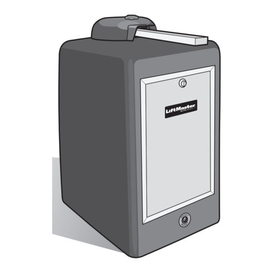
VEHICULAR SWING GATE OPERATOR
Your model may look different than the model illustrated in this manual.
• THIS PRODUCT IS TO BE INSTALLED AND SERVICED BY A TRAINED GATE SYSTEMS
• Visit www.liftmaster.com to locate a professional installing dealer in your area.
• This model is for use on vehicular passage gates ONLY and not intended for use on
• This model is intended for use in Class I, II, III and IV vehicular swing gate applications.
UL991
UL325
compliant
compliant
LiftMaster
845 Larch Avenue
Elmhurst, IL 60126-1196
OWNER'S MANUAL
Model CSW200UL8™
TECHNICIAN ONLY.
pedestrian passage gates.
Advertisement
Table of Contents
Troubleshooting

Subscribe to Our Youtube Channel
Related Manuals for Chamberlain CSW200UL8


Summary of Contents for Chamberlain CSW200UL8
- Page 1 VEHICULAR SWING GATE OPERATOR OWNER’S MANUAL Model CSW200UL8™ Your model may look different than the model illustrated in this manual. • THIS PRODUCT IS TO BE INSTALLED AND SERVICED BY A TRAINED GATE SYSTEMS TECHNICIAN ONLY. • Visit www.liftmaster.com to locate a professional installing dealer in your area.
-
Page 3: Table Of Contents
THE GATE WILL NOT OPERATE WITH REMOTE ....42 CSW200UL8™ MODELS OVERVIEW ......2 UL325 MODEL CLASSIFICATIONS . -
Page 4: Specifications And Warnings
SPECIFICATIONS AND WARNINGS CSW200UL8™ MODELS OVERVIEW Single Motor and Stainless Models CSW200UL8™ (Single Motor) 1/2 HP Motor, 120 Vac, 4 Amp. Maximum Gate Length – 20 ft. Maximum Gate Weight – 600 lbs. DC2000™ Maximum Pull – 125 lbs. Back-Up CSW200ULDC8™... -
Page 5: Ul325 Model Classifications
SPECIFICATIONS AND WARNINGS UL325 MODEL CLASSIFICATIONS The CSW200UL8™ is intended for use in vehicular swing gate applications: Class I – Residential vehicular gate operator A vehicular gate operator (or system) intended for use in a home of one-to four single family dwellings, or a garage or parking area associated therewith. -
Page 6: Safety Installation Information
SPECIFICATIONS AND WARNINGS SAFETY INSTALLATION INFORMATION 1. Vehicular gate systems provide convenience and security. Gate systems are comprised of many component parts. The gate operator is only one component. Each gate system is specifically designed for an individual application. 2. Gate operating system designers, installers and users must take into account the possible hazards associated with each individual application. -
Page 7: Gate Construction Information
SPECIFICATIONS AND WARNINGS GATE CONSTRUCTION INFORMATION Vehicular gates should be installed in accordance with ASTM F2200: Standard Specification for Automated Vehicular Gate Construction. For a copy, contact ASTM directly at 610-832-9585 or www.astm.org. 1. General Requirements Gates shall be constructed in accordance with the 3.1.4 Positive stops shall be required to limit travel to the provisions given for the appropriate gate type listed, refer... -
Page 8: Required Entrapment Protection Device Locations
SPECIFICATIONS AND WARNINGS REQUIRED ENTRAPMENT PROTECTION DEVICE LOCATIONS To prevent SERIOUS INJURY or DEATH from a moving gate: • Entrapment protection devices MUST be installed to protect anyone who may come near a moving gate. • Locate entrapment protection devices to protect in BOTH the open and close gate cycles. •... -
Page 9: Required Entrapment Protection Device Locations
SPECIFICATIONS AND WARNINGS REQUIRED ENTRAPMENT PROTECTION DEVICE LOCATIONS To prevent SERIOUS INJURY or DEATH from a moving gate: • Entrapment protection devices MUST be installed to protect anyone who may come near a moving gate. • Locate entrapment protection devices to protect in BOTH the open and close gate cycles. •... -
Page 10: Safety Installation Information
SPECIFICATIONS AND WARNINGS SAFETY INSTALLATION INFORMATION THE CSW200UL8™ IS FOR USE ON VEHICULAR PASSAGE GATES ONLY AND NOT INTENDED FOR USE ON PEDESTRIAN PASSAGE GATES. Property owners MUST never mount any gate operating device near the gate's path! To prevent SERIOUS INJURY or DEATH from a moving gate: •... -
Page 11: Installation
INSTALLATION INSTALLATION SETUPS NOTE: Weld a horizontal bar across entire gate on any installation for strength. Single Operator Maximum gate length 20 ft. (22 ft. for 1HP) Maximum gate weight is 600 lbs. (800 lbs. for DM) (1000 lbs. 1HP) Warning Placard on both sides of gate. -
Page 12: Concrete Pad And Arm Attachment
INSTALLATION CONCRETE PAD AND ARM ATTACHMENT To AVOID damaging operator, DO NOT weld ANY supports to chassis. Chassis MUST be allowed to flex during operation. Top View of Chassis Concrete Anchors 1/2" x 3-1/2" 19" 5-1/4" 3-7/8" Above 6" 3-5/8" Ground 14"... -
Page 13: Standard Installation Layout
INSTALLATION STANDARD INSTALLATION LAYOUT Sample of standard arm attachment is shown on previous page. Top View of Closed Gate Bracket Length Gate Hinge Bracket Position Mount bracket at least a quarter of the gate length from the gate hinge. NOTE: Longer gates or retro-fits may require both arms to be lengthened by equal parts. Drawing not to scale Gate Hinge Center Gate Open 90°... -
Page 14: Compact Installation Layout
INSTALLATION COMPACT INSTALLATION LAYOUT Compact Installation ONLY! DO NOT use these measurements for a standard installation. (For standard installation, see previous page.) It is necessary to protect against the entrapment that could occur with this type of installation. (See entrapment protection devices.) 20"... -
Page 15: Uphill Driveway Installation (Optional)
INSTALLATION UPHILL DRIVEWAY INSTALLATION (OPTIONAL) Not Possible Gate hits driveway. Possible Special swivel arm and hinges are required. Swivel Arm POST MOUNTING PLATE INSTALLATION (OPTIONAL) 3" heavy steel posts can be U-bolted to mounting plate and cemented in ground. Power and control wiring can be run in separate conduits. -
Page 16: Gate Arm Installation
INSTALLATION GATE ARM INSTALLATION Incorrect Installation! Gate Open Gate Closed Correct Installation Once the gate arm measurements are calculated: 1. Weld the bracket on the gate. 2. Weld the longer arm..3..then weld the shorter arm. Arm is on TOP of bracket. Completely weld around the rectangular tubes and bracket! OUTPUT SHAFT ADJUSTMENT 1. -
Page 17: Control Board Description
INSTALLATION CONTROL BOARD DESCRIPTION 1 HP Board Plug-In Loop Detectors Maglock/Solenoid Relay Module Connection Surge Suppressor UL Alarm Connection Primary/Secondary Connection Photoelectric Sensor Connection W4 Jumper Wire Plug-In Loop Wires OmniControl™ Board Connection 1. 1HP Connection - Factory installed CSW200UL1HP8™ 12. -
Page 18: Surge Suppressor Terminal Connections
Primary/Secondary Connection SURGE SUPPRESSOR TERMINAL CONNECTIONS Output Power Ground 24 Vdc 120 Vac Power Removable Terminals To ENSURE proper operation of external devices: • ENSURE bare wires make good contact inside removable terminal connections. • DO NOT let wire insulation interfere with connection. -
Page 19: Wiring
WIRING To reduce the risk of SEVERE INJURY or DEATH: • DO NOT install ANY wiring or attempt to run the operator without consulting the wiring diagram. We recommend that • ANY maintenance to the operator or in the area near the you Install an optional reversing edge BEFORE proceeding operator MUST not be performed until disconnecting the with the control station installation. -
Page 20: Vac Power Connection
WIRING 120 VAC POWER CONNECTION On-Off switch for operator Connect the black, white and ground wire from the upper junction box to the 120 Vac power supply. Use a 20 amp dedicated circuit for each operator. Green Ground Input power 120 Vac, 60 Hz. White Neutral Black 120 Vac Earth Ground Rod Highly Recommended! -
Page 21: Linking Primary/Secondary Operators
WIRING LINKING PRIMARY/SECONDARY OPERATORS Use a 20 amp dedicated power circuit for each operator. Never run high voltage and low voltage wires in same conduit. Run low voltage 16-18 gauge wire in UL approved conduit to link operators together. Primary Board Secondary Board Primary/Secondary control boards are interchangeable. -
Page 22: Solenoid/Maglock Relay Connection
WIRING SOLENOID/MAGLOCK RELAY CONNECTION Connection of a solenoid or magnetic lock can be made using the J7 board connector and “Optional” Relay Adapter Module. Relay Contact Rating 2 Amp - 125 AC/DC 2 Amp switching load capability... -
Page 23: Factory Installed Dc2000™ Connection
WIRING FACTORY INSTALLED DC2000™ CONNECTION DC2000™ Startup 1. Plug in the 12 pin plug into the DC2000™ control unit. Make sure the “System ON” and “Charge OK” LEDs are lit. If the “Battery Low” led comes on, the battery needs to charge before it can be used. -
Page 24: Dc2000™ Device Wiring
WIRING DC2000™ DEVICE WIRING Manually Operated DC2000™ Devices Manual external devices should be dry-contact which do not consume any current like push buttons or a key switch. Key switch is for property owner’s emergency access ONLY. DO NOT USE FOR AN EMERGENCY FIRE/POLICE KEY ACCESS. Contact your local Fire/Police municipalities for more information on correct Fire/Police emergency key access. -
Page 25: Plug-In Loop Detector Wiring
WIRING PLUG-IN LOOP DETECTOR WIRING Plug-In Loop Detectors See Accessories. The wire MUST be twisted together Series Connected minimum 6 twists To AVOID damaging control board, disconnect per foot from the all power to operator before installing plug-in end of the loop to loop detectors. -
Page 26: Vac External Loop Detector Wiring
WIRING 120 VAC EXTERNAL LOOP DETECTOR WIRING See Accessories 120 Vac “Center” Loop Detector: Allows gate to stay open when vehicles are obstructing path. CAUTION: This option is for all vehicles including ones less than 14 feet long. Center loop system requires two safety loops. Center Loop 120 Vac “Safety”... -
Page 27: Entrapment Protection Devices
WIRING ENTRAPMENT PROTECTION DEVICES Contact Sensors (Edge Sensor) NOTE: When touched, these electrically activated edge sensors immediately signal the gate operator to stop and reverse. To prevent SERIOUS INJURY or DEATH from a moving gate: Property owners are obligated to test edges monthly. •... -
Page 28: Entrapment Protection Devices
WIRING ENTRAPMENT PROTECTION DEVICES Non-Contact Sensors (12 Vdc Photoelectric Sensors) NOTE: Property owners are obligated to test photoelectric sensors To prevent SERIOUS INJURY or DEATH from a moving gate: monthly. • Locate entrapment protection devices to protect in BOTH the See Accessories for part number. -
Page 29: Adjustments
ADJUSTMENTS SET GATE OPENING DIRECTION To reduce the risk of SERIOUS INJURY or DEATH: Disconnect power BEFORE performing ANY adjustments. Open to the RIGHT Open to the LEFT... -
Page 30: Limit Switch Adjustment
ADJUSTMENTS LIMIT SWITCH ADJUSTMENT Release the red handle and move the gate to the open position. Loosen the screw on one of the limit cams and turn the cam until the half moon shape hits the limit switch and you hear the switch click. Tighten cam. Move gate to the closed position and do the same with the other limit cam. -
Page 31: Radio Receiver Programming
ADJUSTMENTS RADIO RECEIVER PROGRAMMING The receiver can be used as a single, two, or three channel receiver and is compatible with Security+ 2.0™ remote controls ONLY. Each channel is compatible with a certain number of To prevent possible SERIOUS INJURY or DEATH from remote controls and keypads. -
Page 32: Setting The Timer
ADJUSTMENTS SETTING THE TIMER Single Operator To use the automatic close for the gate system the timer switch should be put in the “ON” position. Set timer 3 to 60 To use the push close command, seconds. the timer should be switched to the “OFF”... -
Page 33: Adjusting Reversing Sensor(S)
ADJUSTMENTS ADJUSTING REVERSING SENSOR(S) Adjust the “Reverse Sensor” on the OmniControl™ board. Alarm Sensor does not need to be adjusted except where noted below. The level of reverse sensitivity depends on the weight of the gate and the condition of installation. Sensor is too sensitive = If the gate stops in mid cycle or reverses by itself. -
Page 34: Omnicontrol™ Board Connections
ADJUSTMENTS OMNICONTROL™ BOARD CONNECTIONS Purchased separately from NOTE: Refer to the LiftMaster . See Accessories. ® OmniControl™ board manual for more specific information. Second Operator Proximity Switch 3-Button Station Dry Contact 12 Vdc House Alarm Stop Button Dry Contact Maglock NOTE: Cut jumper W4 wire for 3 button station or stop button. -
Page 35: Maintenance And Operation
MAINTENANCE AND OPERATION IMPORTANT SAFETY INSTRUCTIONS To reduce the risk of SEVERE INJURY or DEATH: 1. READ AND FOLLOW ALL INSTRUCTIONS. 5. Use the emergency release ONLY when the gate is not moving. 2. NEVER let children operate or play with gate controls. Keep the remote control away from children. -
Page 36: Built-In Reset Switch
MAINTENANCE AND OPERATION BUILT-IN RESET SWITCH When the gate operator’s audio alarm has been tripped (see below), the reset switch must be pushed for the operator to function again. The reset switch will shut off an activated audio alarm and reset the operator to function again. -
Page 37: Manual Disconnect
MAINTENANCE AND OPERATION MANUAL DISCONNECT NOTE: Use the dedicated breaker switch to disconnect power to the operator. To reduce the risk of SERIOUS INJURY: DO NOT grab the operator arm to move the gate or your fingers could get pinched. 1. -
Page 38: Wiring Diagrams
WIRING DIAGRAMS CSW200UL8™ AND CSW200ULDM8™ NOTE: See table on next page. -
Page 39: Wiring Table Csw200Ul8™ And Csw200Uldm8
WIRING DIAGRAMS WIRING TABLE CSW200UL8™ AND CSW200ULDM8™ OmniControl™ Board J Pin # Signal Type Direction Level (+/- 10%) Input Connection Safety Loop 5 or 0 Vdc External Loop Detector Wires, 120 Vac Input Power Neutral Power, Radio Receiver, Strike Open, Key... -
Page 40: Csw200Ul1Hp8
WIRING DIAGRAMS CSW200UL1HP8™ NOTE: See table on next page. -
Page 41: Wiring Table Csw200Ul1Hp8
WIRING DIAGRAMS WIRING TABLE CSW200UL1HP8™ OmniControl™ Board J Pin # Signal Type Direction Level (+/- 10%) Input Connection Safety Loop 5 or 0 Vdc External Loop Detector Wires, 120 Vac Power, Input Power Neutral Radio Receiver, Strike Open, Key Switch Center Loop 5 or 0 Vdc Harness... -
Page 42: Wiring Diagram Dc2000™ For Single And Dm
WIRING DIAGRAMS WIRING DIAGRAM DC2000™ FOR SINGLE AND DM NOTE: This diagram only shows the DC2000™ wiring and all other wiring not shown is the same as the diagram on page 36. The 1 HP models Can Not have the DC2000™... -
Page 43: Wiring Table Dc2000
WIRING DIAGRAMS WIRING TABLE DC2000™ J Pin # Signal Type Direction Level (+/- 10%) Input Connection Open N.O. 5 or 0 Vdc • Manual Three Button (Dry) Reset Switch Closed N.O. 5 or 0 Vdc Stop N.O. 5 or 0 Vdc Reset Switch Common •... -
Page 44: Troubleshooting
TROUBLESHOOTING THE GATE WILL NOT OPERATE WITH REMOTE The radio receiver LED on the control board remains “ON” The radio receiver LED on the control board remains “OFF” when using the remote control. when using the remote control. 1. Probable Cause: Remote control battery is dead. 1. -
Page 45: Troubleshooting Chart
TROUBLESHOOTING TROUBLESHOOTING CHART Condition Probable Causes Solution Overload LED ON and Power 1. Short circuit at terminals 11 and 13. 1. Remove the short circuit condition at the LED OFF 2. Short circuit at any of the loop detectors in terminals. -
Page 46: Repair Parts
REPAIR PARTS REPAIR PARTS ILLUSTRATIONS K75-36768 K45-50676 Q084 Q118 Q268 Q062 K75-35400-2 Q061 Q059 Q057 Q216 K75-36763 Q018 Q044 850LM Q210 Q407 Q521 Q520 Q027 K10-36697 Q212 Q025 Q029* Q166 Q018 K75-34709-4 Q175 Q183 Q025 K10-36700 Q046 Q400E-1 Q045 Q042 Q163 K73-36687 Q401... -
Page 47: How To Order Repair Parts
Q183 - Sprocket (B50-16) Q212 - Gear Reducer 40-30:1 Q216 - Output Shaft for 70 Reducer Electronic Box Assembly - K75-34709-4 K73-36687 - CSW200UL8™ Chassis for 70 Reducer - Electronic Metal Box K75-35400-2 - Cover - HD Polyethylene - Surge Suppressor... -
Page 48: Accessories
ACCESSORIES Remote Controls Part # 893MAX Part # 811LM Part # 890MAX Standard Arm Part # Q104 Magnetic Lock (Outdoor) Omni Relay Adapter Part # MG1300 Swivel Arm Part # Q400MAU Part # Q103 For more information about accessories: Heater Kit www.liftmaster.com Part # G6518CSW Stop Button... -
Page 49: Installation Checklist
INSTALLATION CHECKLIST 1. Owner and Installer must read all warnings and safety precautions. 2. Make sure concrete mounting pad is big enough and deep enough for operator. 3. Operator must be securely fastened to concrete pad or mounting plate. 4. Operator arm must be level and welded properly to gate. 5. -
Page 50: Warranty Policy
7 year residential/ 5 year commercial from the date of purchase [and that the CSW200UL8™ is free from defect in materials and/or workmanship for a period of 7 year residential/ 5 year commercial from the date of purchase]. - Page 52 845 Larch Avenue Elmhurst, Illinois 60126-1196 01-36717D © 2014, LiftMaster – All Rights Reserved...
Need help?
Do you have a question about the CSW200UL8 and is the answer not in the manual?
Questions and answers