Table of Contents
Advertisement
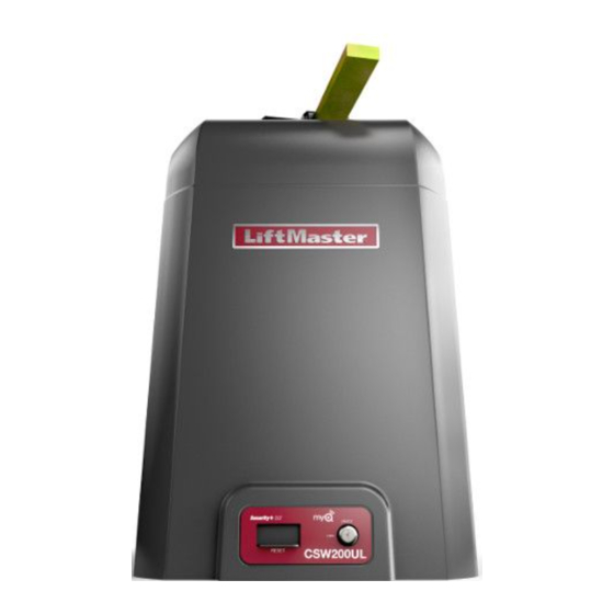
ELITE SERIES COMMERCIAL HIGH-TRAFFIC
AC SWING GATE OPERATOR
CSW200101UL
1 HP Single Phase
CSW200501UL
1/2 HP Single Phase
LiftMaster
300 Windsor Drive
Oak Brook, IL 60523
INSTALLATION MANUAL
• THIS PRODUCT IS TO BE INSTALLED AND
SERVICED BY A TRAINED GATE SYSTEMS
TECHNICIAN ONLY.
• This model is for use on vehicular passage
gates ONLY and not intended for use on
pedestrian passage gates.
• This model is intended for use in Class I, II, III
and IV vehicular swing gate applications.
• Visit LiftMaster.com to locate a professional
installing dealer in your area.
• This gate operator is compatible with MyQ
and Security+ 2.0
®
Access installation and technical support
Ac
guides or register this product
CSW200ULTECH
accessories.
Take a photo of the camera
1.
icon including the points ( ).
Send it in by texting the
2.
photo to 71403.
®
Advertisement
Table of Contents
Troubleshooting

Related Manuals for Chamberlain Elite CSW200501UL


Summary of Contents for Chamberlain Elite CSW200501UL
- Page 1 ELITE SERIES COMMERCIAL HIGH-TRAFFIC AC SWING GATE OPERATOR INSTALLATION MANUAL • THIS PRODUCT IS TO BE INSTALLED AND SERVICED BY A TRAINED GATE SYSTEMS TECHNICIAN ONLY. • This model is for use on vehicular passage gates ONLY and not intended for use on pedestrian passage gates.
-
Page 2: Table Of Contents
TABLE OF CONTENTS Photoelectric Sensors and Edge Sensors ..........30 SAFETY Locks ....................30 Safety Symbol and Signal Word Review ..........2 Usage Class .................... 3 EXPANSION BOARD OVERVIEW UL325 Entrapment Protection Requirements ......... 3 EXIT FAIL Switch .................. 31 Safety Installation Information .............. -
Page 3: Usage Class
SAFETY Usage Class Class I - Residential Vehicular Gate Operator A vehicular gate operator (or system) intended for use in garages or parking areas associated with a residence of one-to four single families. Class II - Commercial/General Access Vehicular Gate A vehicular gate operator (or system) intended for use in a commercial location or building such as a multi-family housing unit (five or more single family units), hotel, garages, retail store, or other buildings... -
Page 4: Safety Installation Information
SAFETY Safety Installation Information 1. Vehicular gate systems provide convenience and security. Gate systems 9. The Stop and/or Reset (if provided separately) must be located in the are comprised of many component parts. The gate operator is only one line-of-sight of the gate. Activation of the reset control shall not cause component. -
Page 5: Gate Construction Information
SAFETY Gate Construction Information Vehicular gates should be installed in accordance with ASTM F2200: Standard Specification for Automated Vehicular Gate Construction. For a copy, contact ASTM directly at 610-832-9585 or www.astm.org. General Requirements Vehicular Horizontal Swing Gate Gates shall be constructed in accordance with the provisions The following provisions shall apply to Class I, Class II and Class III given for the appropriate gate type listed, refer to ASTM F2200 vehicular horizontal swing gates:... -
Page 6: Introduction
INTRODUCTION Carton Inventory NOT SHOWN: Documentation packet and hardware bag Tools Needed 1/2" wrench for cover screw 5/16", 3/4" wrench for 1/2" concrete anchors, Screwdrivers (phillips head and flat head), Cable cutters and strippers... -
Page 7: Operator Specifications
INTRODUCTION Operator Specifications Usage Classification Class I, II, III, & IV Main AC Supply Model CSW200501UL 1/2 HP: 120 Vac, 6 Amps (12 Amps including accessory outlets) Model CSW200101UL 1 HP: 120 Vac, 12 Amps (18 Amps including accessory outlets) When Optional Transformer Kit Model 3PHCONV is installed in the field, operator is rated 208/240/480/575 VAC, 4.8/4.2/2.1/1.7 A, 60 Hz, 1 PH Accessory Power... - Page 8 INTRODUCTION CSW200101UL 1 HP...
-
Page 9: Site Preparation
INTRODUCTION Site Preparation Check the national and local building codes BEFORE installation. Gate Conduit and Concrete Pad Gate must be constructed and installed according to ASTM F2200 Trench and install conduit. Before trenching, contact underground standards (refer to page 4). Gate must fit specifications of operator utility locating companies. -
Page 10: Installation
INSTALLATION Types of Installations Standard Installation The illustration is an example of a standard installation. Compact Installation The illustration is an example of a compact installation. If the operator arm will hit an obstruction when the gate is in the open position, refer to LiftMaster.com for compact installation instructions. -
Page 11: Step 1 Determine Location For Operator
INSTALLATION To AVOID damaging gas, power or other underground utility lines, DO NOT touch the heater when switch is on, heater may be hot. contact underground utility locating companies BEFORE digging more than 18 inches (46 cm) deep. Step 1 Determine Location for Operator DO NOT run the operator until instructed. - Page 12 INSTALLATION Chart Installation Refer to the illustration to determine the measurements and location of the concrete pad. Dimension (A) thru (E) are from the center of one pivot point to the center of another pivot point. Caution: If the gate is longer than 18 feet (5.5 m), follow CHART A: A-2. Suggestion: The dimensions between the gate and the concrete pad is always 10 inches (25.4 cm) less than the dimension D.
-
Page 13: Step 2 Install The Operator
INSTALLATION Step 2 Install the Operator CHECK the national and local building codes before installation. 1. Install the electrical conduit. 2. Pour a concrete pad (reinforced concrete is recommended). The concrete pad should be 6 inches (15.2 cm) above the ground and deeper than the frost line. -
Page 14: Step 3 Position Gate Bracket
INSTALLATION Step 3 Position Gate Bracket NOTE: It may be necessary to attach horizontal reinforcement to the gate before attaching the gate bracket. 1. Position the operator arm onto the output shaft so that the pin slides into the slot. 2. -
Page 15: Step 5 Secure The Operator Arm
INSTALLATION Step 5 Secure the Operator Arm Once the operator arm measurements are verified: 1. Weld the gate bracket to the gate. 2. Weld the short arm section. 3. Weld the long arm section. 4. Remove the set screws from the arm. NOTE: Completely weld around the outer tubing and bracket. -
Page 16: Step 6 Install Entrapment Protection
INSTALLATION To prevent SERIOUS INJURY or DEATH from a moving gate: ALL gate operator systems REQUIRE two independent entrapment Locate entrapment protection devices to protect in BOTH the open and protection systems for each entrapment zone. close gate cycles. Entrapment protection devices MUST be installed to protect anyone Locate entrapment protection devices to protect between moving gate who may come near a moving gate. - Page 17 INSTALLATION Wire Entrapment Protection Devices There are three options for wiring the entrapment protection devices depending on the specific device and how the device will function. Refer to the specific entrapment protection device manual for more information. These entrapment protection device inputs are for monitored devices, which include pulsed photoelectric sensors, resistive edge sensors, and pulsed edge sensors.
-
Page 18: Step 7 Earth Ground Rod
INSTALLATION Step 7 Earth Ground Rod Use the proper earth ground rod for your local area. The ground wire must be a single, whole piece of wire. Never splice two wires for the ground wire. If you should cut the ground wire too short, break it, or destroy its integrity, replace it with a single wire length. - Page 19 INSTALLATION All control wiring used to connect external devices to Class 2 circuits of the operator must be (QPTZ) Power-Limited Circuit Cables, Type CL2, CL2P, CL2R, or CL2X or other cable with equivalent or better electrical, mechanical, and flammability ratings. Power wiring 1.
-
Page 20: Step 9 Dual Gate Setup
INSTALLATION Step 9 Dual Gate Setup There are two options for dual gate communication: wired or wireless. Follow the directions according to your application. Do not use wired and wireless communication simultaneously. Wireless setup To activate the wireless feature: 1. Choose an operator to be the network primary operator. All wireless accessories will need to be programmed to the primary operator. NOTE: We recommend that all accessories and board configurations are set on the primary operator. - Page 21 INSTALLATION DUAL GATE WIRE TYPE (SHIELDED TWISTED PAIR CABLE) Wired setup 22AWG up to 200 feet (61 m) 18AWG - 200-1000 feet (61-305 m) Before digging, contact local underground utility locating companies. Use Wire must be rated at 30 Volt minimum PVC conduit to prevent damage to cables. 1.
-
Page 22: Step 10 Install The Cover
INSTALLATION Step 10 Install the Cover Before installing the cover, follow the instructions in the Adjustment section to set the handing and limits. The operator cover consists of two pieces: a rear cover and a front cover. The front cover can easily be removed to access the electrical box. To access the reset switch slide the access door up. -
Page 23: Adjustment
ADJUSTMENT Adjust the Handing and Limits To reduce the risk of SEVERE INJURY or DEATH: Without a properly installed safety reversal system, persons NEVER use force adjustments to compensate for a binding or sticking (particularly small children) could be SERIOUSLY INJURED or gate. -
Page 24: Fine Tune The Force
ADJUSTMENT Readjust the Limits To readjust the limits, follow the “Set the Limits” and “Set the Force and Run Distance” instructions above. It is important that the force and run distance are set after every limit readjustment. Fine Tune the Force Once the initial limits have been set, the REVERSAL FORCE DIAL on the control board is used for fine tuning the force where wind or environmental changes may affect the gate travel. -
Page 25: Operator Overview
OPERATOR OVERVIEW... -
Page 26: Control Board Overview
CONTROL BOARD OVERVIEW... -
Page 27: Learn Button
CONTROL BOARD OVERVIEW Learn Button The LEARN button is used for programming (refer to Programming). Diagnostic Display The diagnostic display will show the operator type, firmware version, and codes. The operator type will display as “SG” followed by a “20” which indicates the operator type as CSW200UL. The firmware version will show after the operator type, example “1.2”. For more information about the codes refer to the Troubleshooting section. -
Page 28: Force Dial
CONTROL BOARD OVERVIEW Reversal Force Dial The REVERSAL FORCE dial adjusts the force. See the Adjustment section. Settings 1-3: Fixed force settings (the force will not adjust due to gate wear or temperature changes) Settings 4-10: Automatically increase the force due to gate wear or temperature changes Test Buttons Used to operate the gate (OPEN, STOP and CLOSE). -
Page 29: Wire Accessories To Control Board
WIRE ACCESSORIES TO CONTROL BOARD All control wiring used to connect external devices to Class 2 circuits of the operator must be (QPTZ) Power-Limited Circuit Cables, Type CL2, CL2P, CL2R, or CL2X or other cable with equivalent or better electrical, mechanical, and flammability ratings. Three Button Control Station TERMINALS FUNCTION... -
Page 30: Photoelectric Sensors And Edge Sensors
WIRE ACCESSORIES TO CONTROL BOARD Photoelectric Sensors and Edge Sensors The EYES/EDGE terminals are used for connecting entrapment protection devices. At least one external monitored entrapment protection devices are required prior to gate movement. Monitored entrapment protection devices should have been installed with the operator at the time of installation. Only ONE monitored device may be connected to each input. -
Page 31: Expansion Board Overview
EXPANSION BOARD OVERVIEW To AVOID damaging the circuit board, relays or accessories, DO NOT connect more than 42 Vdc (32 Vac) to the AUX relay contact terminal blocks. EXIT FAIL Switch OPEN: If the EXIT plug-in loop detector (model LOOPDETLM) detects a fault, then the gate will open and remain open until fault is cleared. CLOSE: If the EXIT plug-in loop detector (model LOOPDETLM) detects a fault, faults are ignored (EXIT loop is faulted and inoperative). -
Page 32: Auxiliary Relay 1 And 2
EXPANSION BOARD OVERVIEW Auxiliary Relay 1 and 2 Normally Open (N.O.) and Normally Closed (N.C.) relay contacts to control external devices, for connection of Class 2, low voltage (42 Vdc [34 Vac] max 5 Amps) power sources only. Function of relay contact activation determined by switch settings. SWITCH SETTINGS AUX RELAY AUX RELAY 1... -
Page 33: Wire Accessories To Expansion Board
WIRE ACCESSORIES TO EXPANSION BOARD Photoelectric Sensors and Edge Sensors The EYES/EDGE terminals are used for connecting entrapment protection devices. At least one external monitored entrapment protection devices are required prior to gate movement. Monitored entrapment protection devices should have been installed with the operator at the time of installation. Only ONE monitored device may be connected to each input. -
Page 34: Loops
WIRE ACCESSORIES TO EXPANSION BOARD Loops TERMINALS FUNCTION WIRING EXAMPLE EXIT Loop wire connection for plug-in loop detector when loop is inside secured area near gate. Open command - opens a closed gate Soft open (maintained switch does not override external safeties and does not reset alarm condition) If maintained, pauses Timer-to-Close at OPEN limit Opens a closing gate and holds open an open gate... -
Page 35: Field Wiring
ADDITIONAL WIRING To protect against fire and electrocution: For continued protection against fire: DISCONNECT power (AC or solar and battery) BEFORE installing or Replace ONLY with fuse of same type and rating. servicing operator. Field Wiring... -
Page 36: Programming
PROGRAMMING Remote Controls (Not Provided) ® A total of 50 Security+ 2.0 remote controls or KPW250 keypads and 2 keyless entries (1 PIN for each keyless entry) can be programmed to the operator. When programming a third keyless entry to the operator, the first keyless entry will be erased to allow the third keyless entry to be programmed. -
Page 37: Liftmaster Internet Gateway (Not Provided)
PROGRAMMING LiftMaster Internet Gateway (not Constant Pressure Override (CPO) provided) Constant Pressure Override is for use with KPW5 and KPW250 keypads (not provided). The KPW5/KPW250 wireless commercial keypads are To program the operator to the LiftMaster Internet Gateway: security keypads and can only be programmed to ONE gate operator (see Using the learn button on the opertaor's control the KPW5/KPW250 manual for complete programming instructions). -
Page 38: Settings
SETTINGS Gate operator setup examples The following are example setups for the gate operator. Your specific site requirements may be different. Always setup the operator system to the site requirements, including all necessary entrapment protection devices. RESIDENTIAL: One to four residential homes sharing a gated entrance/exit, allowing vehicle access trumps security concerns COMMERCIAL/GENERAL ACCESS: A residential community (more than four homes) having one or more gated entrances/exits, allowing vehicle access trumps security concerns COMMERCIAL: Business site where security (gate closed) is important... -
Page 39: Dual Gate Settings
SETTINGS Dual Gate Settings NOTE: We recommend that all accessories and board configurations are set on the primary operator. Main Control Board FEATURE PRIMARY OPERATOR SECONDARY OPERATOR Timer-to-Close Set the TTC dial to desired setting Bi-Part Delay Switch Bi-Part Delay: ON (will open last and close first) Bi-Part Delay: OFF (will open first and close last) Tandem Mode: OFF Tandem Mode: OFF... -
Page 40: Maintenance
MAINTENANCE IMPORTANT SAFETY INSTRUCTIONS To reduce the risk of SEVERE INJURY or DEATH: READ AND FOLLOW ALL INSTRUCTIONS. Test the gate operator monthly. The gate MUST reverse on contact with an object or reverse when an object activates the noncontact ANY maintenance to the operator or in the area near the operator sensors. -
Page 41: Troubleshooting
TROUBLESHOOTING To protect against fire and electrocution: For continued protection against fire: DISCONNECT power (AC or solar and battery) BEFORE installing or Replace ONLY with fuse of same type and rating. servicing operator. Diagnostic Codes To View the Codes The codes will show on the diagnostic display. The operator will show the code sequence number followed by the code number: To Exit... -
Page 42: Diagnostic Codes Table
TROUBLESHOOTING Diagnostic Codes Table Some codes are saved in the code history and some are not. If a code is not saved it will briefly appear on the display as it occurs, then disappear. External Entrapment Inherent Entrapment LiftMaster System Installed System Informational Protection... - Page 43 TROUBLESHOOTING Code Meaning Solution Saved CLOSE EYE/INTERRUPT triggered, causing reversal, preventing close, or resetting TTC CLOSE EDGE triggered, causing reversal, NO IF an obstruction occurred, no action required. If an obstruction did NOT preventing close, or canceling TTC occur, check alignment, inputs, and wiring on main control board OPEN EYE/EDGE triggered, causing reversal or preventing opening CLOSE EYE/INTERRUPT triggered, causing...
-
Page 44: Operator Alarm
TROUBLESHOOTING Operator Alarm If a contact sensor detects an obstruction twice consecutively the alarm will sound (up to 5 minutes) and the operator will need to be reset. When the inherent force of the operator (RPM/current sensor) detects the following (twice consecutively) the alarm will sound (up to 5 minutes) and the operator will need to be reset. -
Page 45: Troubleshooting Chart
TROUBLESHOOTING Troubleshooting Chart SYMPTOM POSSIBLE CAUSES SOLUTIONS Operator does not a. No power to control board a. Check AC power run and diagnostic b. Open fuse b. Check fuses display not on. c. Defective control board c. Replace defective control board Control board a. - Page 46 TROUBLESHOOTING SYMPTOM POSSIBLE CAUSES SOLUTIONS Obstruction in a. Force adjustment needed a. Refer to the Adjustment section to conduct the obstruction test and gate's path does perform the proper force adjustment that is needed. not cause gate to stop and reverse. Photoelectric a.
-
Page 47: Accessories
ACCESSORIES Universal single and 3-button remote LiftMaster elite series maglock package controls Model MG1300RLYPKG Ideal for applications requiring a large number of remote controls. Models 811LM and 813LM ® Security+ 2.0 learning remote controls Heater kit accessory One button can control a gate operator and the other(s) can control garage door(s). - Page 48 ACCESSORIES Entrapment protection If the gate opening distance is greater than the maximum separation distance of the photoelectric sensors, then edge sensors MUST BE USED. Refer to the photoelectric sensor instructions for maximum separation distance. LiftMaster monitored through beam photoelectric sensor Model LMTBUL LiftMaster monitored retro-reflective photoelectric sensor...
-
Page 49: Repair Parts
REPAIR PARTS CSW200501UL 1/2 HP NOT SHOWN Plastic Standoffs for main control board (10 per K77-37683 bag) Reset Button with ID K94-37449 Hall Effect Sensor Board K1D8247 Wire Harnesses (main board to power board, main K77-37693 board to ground, main board to transformer, and power board to transformer) Wire Harness (main board to expansion board) K94-34778... -
Page 50: Csw200101Ul 1 Hp
REPAIR PARTS CSW200101UL 1 HP NOT SHOWN Plastic Standoffs for main control board (10 per K77-37683 bag) Reset Button with ID K94-37449 Hall Effect Sensor Board K1D8247 Wire Harnesses (main board to power board, main K77-37693 board to ground, main board to transformer, and power board to transformer) Wire Harness (main board to expansion board) K94-34778... -
Page 51: Warranty
WARRANTY LiftMaster 7 Year residential / 5 Year Commercial Limited Warranty LiftMaster (“Seller”) warrants to the first purchaser of this product, for the structure in which this product is originally installed, that it is free from defect in materials and/or workmanship for a period of 7 Year residential / 5 Year Commercial from the date of purchase [and that the CSW200UL is free from defect in materials and/or workmanship for a period of 7 Year residential / 5 Year Commercial from the date of purchase]. - Page 52 300 Windsor Drive Oak Brook, IL 60523 LiftMaster.com © 2018, The Chamberlain Group, Inc. - All Rights Reserved 01-39374B...
Need help?
Do you have a question about the Elite CSW200501UL and is the answer not in the manual?
Questions and answers
How to program the gate to open at 6am and close at 6pm daily.