Table of Contents
Advertisement
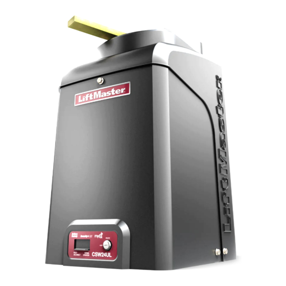
VEHICULAR SWING GATE OPERATOR
LiftMaster
300 Windsor Drive
Oak Brook, IL 60523
COMMERCIAL DC
INSTALLATION MANUAL
• THIS PRODUCT IS TO BE INSTALLED AND
SERVICED BY A TRAINED GATE SYSTEMS
TECHNICIAN ONLY.
• This model is for use on vehicular passage
gates ONLY and not intended for use on
pedestrian passage gates.
• This model is intended for use in Class I, II,
III and IV vehicular swing gate applications.
• Visit LiftMaster.com to locate a professional
installing dealer in your area.
• This gate operator is compatible with MyQ
and Security+ 2.0
Acce
Access installation and technical support
guides or register this product
guid
CSW24ULTECH
accessories.
®
Take a photo of the camera
1.
icon including the points ( ).
Send it in by texting the
2.
photo to 71403.
®
Advertisement
Table of Contents
Troubleshooting

Related Manuals for Chamberlain CSW24UL


Summary of Contents for Chamberlain CSW24UL
- Page 1 COMMERCIAL DC VEHICULAR SWING GATE OPERATOR INSTALLATION MANUAL • THIS PRODUCT IS TO BE INSTALLED AND SERVICED BY A TRAINED GATE SYSTEMS TECHNICIAN ONLY. • This model is for use on vehicular passage gates ONLY and not intended for use on pedestrian passage gates.
-
Page 2: Table Of Contents
TABLE OF CONTENTS OPERATION SAFETY Gate Operator Setup Examples ............28 Safety Symbol and Signal Word Review ..........2 Control Board Overview ...............29 Usage Class ...................3 Manual Disconnect ................30 UL325 Entrapment Protection Requirements ........3 Reset Switch ..................30 Safety Installation Information ...............4 Operator Alarm ..................30 Gate Construction Information ...............5 Remote Control ..................30 INTRODUCTION... -
Page 3: Usage Class
SAFETY Usage Class Class I - Residential Vehicular Gate Operator A vehicular gate operator (or system) intended for use in garages or parking areas associated with a residence of one-to four single families. Class II - Commercial/General Access Vehicular Gate A vehicular gate operator (or system) intended for use in a commercial location or building such as a multi-family housing unit (five or more single family units), hotel, garages, retail store, or other buildings... -
Page 4: Safety Installation Information
SAFETY Safety Installation Information 1. Vehicular gate systems provide convenience and security. Gate systems 9. The Stop and/or Reset (if provided separately) must be located in the are comprised of many component parts. The gate operator is only one line-of-sight of the gate. Activation of the reset control shall not cause component. -
Page 5: Gate Construction Information
SAFETY Gate Construction Information Vehicular gates should be installed in accordance with ASTM F2200: Standard Specification for Automated Vehicular Gate Construction. For a copy, contact ASTM directly at 610-832-9585 or www.astm.org. General Requirements Vehicular Horizontal Swing Gate Gates shall be constructed in accordance with the provisions The following provisions shall apply to Class I, Class II and Class III given for the appropriate gate type listed, refer to ASTM F2200 vehicular horizontal swing gates:... -
Page 6: Introduction
INTRODUCTION Carton Inventory NOT SHOWN: Documentation packet and hardware bag... -
Page 7: Operator Specifications
INTRODUCTION Operator Specifications Usage Classification Class I, II, III, & IV Main AC Supply 120 Vac, 4 Amps (10 Amps including Accessory Outlets) OR 240 Vac, 2 Amps When Optional Transformer Kit Model 3PHCONV is installed in the field, operator is rated 208/240/480/575 VAC, 4.8/4.2/2.1/1.7 A, 60 Hz, 1 PH System Operating Voltage 24 Vdc Transformer Run / Battery Backup... -
Page 8: Site Preparation
INTRODUCTION Site Preparation Check the national and local building codes BEFORE installation. Gate Conduit and Concrete Pad Gate must be constructed and installed according to ASTM F2200 Trench and install conduit. Before trenching, contact underground utility standards (refer to page 4). Gate must fit specifications of operator (refer locating companies. -
Page 9: Installation
INSTALLATION Types of Installations Standard Installation The illustration is an example of a standard installation. Compact Installation The illustration is an example of a compact installation. If the operator arm will hit an obstruction when the gate is in the open position, refer to LiftMaster.com for compact installation instructions. -
Page 10: Step 1 Determine Location For Concrete Pad And Operator
INSTALLATION To AVOID damaging gas, power or other underground utility lines, ALWAYS wear protective gloves and eye protection when changing contact underground utility locating companies BEFORE digging more the battery or working around the battery compartment. than 18 inches (46 cm) deep. Step 1 Determine Location for Concrete Pad and Operator DO NOT run the operator until instructed. - Page 11 INSTALLATION Chart Installation Refer to the illustration to determine the measurements and location of the concrete pad. Dimension (A) thru (E) are from the center of one pivot point to the center of another pivot point. Caution: If the gate is longer than 18 feet (5.5 m), follow CHART A: A-2. Suggestion: The dimensions between the gate and the concrete pad is always 10 inches (25.4 cm) less than the dimension D.
-
Page 12: Step 2 Concrete Pad And Operator Attachment
INSTALLATION Step 2 Concrete Pad and Operator Attachment CHECK the national and local building codes before installation. NOTE: When lifting the operator use the handle to avoid damaging the operator 1. Install the electrical conduit. 2. Pour a concrete pad (reinforced concrete is recommended). The concrete pad should be 6 inches (15.2 cm) above the ground and deeper than the frost line. -
Page 13: Step 3 Position The Gate Bracket
INSTALLATION Step 3 Position the Gate Bracket NOTE: It may be necessary to attach horizontal reinforcement to the gate before attaching the gate bracket. 1. Position the operator arm onto the output shaft so that the pin slides into the slot. 2. -
Page 14: Step 5 Secure The Operator Arm
INSTALLATION Step 5 Secure the Operator Arm Once the operator arm measurements are verified: 1. Weld the gate bracket to the gate. 2. Weld the short arm section. 3. Weld the long arm section. 4. Remove the set screws from the arm. NOTE: Completely weld around the outer tubing and bracket. -
Page 15: Step 6 Install Entrapment Protection
INSTALLATION To prevent SERIOUS INJURY or DEATH from a moving gate: ALL gate operator systems REQUIRE two independent entrapment Locate entrapment protection devices to protect in BOTH the open and protection systems for each entrapment zone. close gate cycles. Entrapment protection devices MUST be installed to protect anyone Locate entrapment protection devices to protect between moving gate who may come near a moving gate. - Page 16 INSTALLATION Wire Entrapment Protection Devices There are three options for wiring the entrapment protection devices depending on the specific device and how the device will function. Refer to the specific entrapment protection device manual for more information. These entrapment protection device inputs are for monitored devices, which include pulsed photoelectric sensors, resistive edge sensors, and pulsed edge sensors.
-
Page 17: Step 7 Earth Ground Rod
INSTALLATION Step 7 Earth Ground Rod Use the proper earth ground rod for your local area. The ground wire must be a single, whole piece of wire. Never splice two wires for the ground wire. If you should cut the ground wire too short, break it, or destroy its integrity, replace it with a single wire length. - Page 18 INSTALLATION All control wiring used to connect external devices to Class 2 circuits of the operator must be (QPTZ) Power-Limited Circuit Cables, Type CL2, CL2P, CL2R, or CL2X or other cable with equivalent or better electrical, mechanical, and flammability ratings. 240 VAC only The accessory outlet is disabled and cannot be used with the 240 Vac option.
-
Page 19: Step 9 Connect Batteries
INSTALLATION AC power switch The AC Power switch on the operator will turn the incoming 120/240 Vac power ON or OFF. The operator's AC Power switch ONLY turns off AC power to the control board and DOES NOT turn off battery power. Step 9 Connect Batteries 7AH battery The batteries are charged in the circuit by the integrated transformer. - Page 20 INSTALLATION 33AH battery The batteries are charged in the circuit by the integrated transformer. The batteries are for battery backup or solar installation. The 33AH application requires the Solar Harness Kit (Model K94-37236) and an additional battery tray (Model K10-34758-2). 1.
-
Page 21: Step 10 Dual Gate Setup
INSTALLATION Step 10 Dual gate setup There are two options for dual gate communication: wired or wireless. Follow the directions according to your application. Do not use wired and wireless communication simultaneously. Wired dual gate applications will have a longer battery standby time than wireless applications. Wireless setup To activate the wireless feature: 1. - Page 22 INSTALLATION Wired setup DUAL GATE WIRE TYPE (SHIELDED TWISTED PAIR CABLE) 22AWG up to 200 feet (61 m) 18AWG - 200-1000 feet (61-305 m) Before digging, contact local underground utility locating companies. Use Wire must be rated at 30 Volt minimum PVC conduit to prevent damage to cables. 1.
-
Page 23: Step 11 Install The Cover
INSTALLATION Step 11 Install the cover Before installing the cover, follow the instructions in the Adjustment section to adjust the limits and force. The operator cover consists of two pieces: a rear cover and a front cover. The front cover can easily be removed to access the electrical box. To access the reset switch slide the access door up. -
Page 24: Adjustment
ADJUSTMENT Limit and Force Adjustment To reduce the risk of SEVERE INJURY or DEATH: Without a properly installed safety reversal system, persons NEVER use force adjustments to compensate for a binding or sticking (particularly small children) could be SERIOUSLY INJURED or gate. -
Page 25: Obstruction Test
ADJUSTMENT Fine Tune the Force Once the initial limits have been set, the REVERSAL FORCE DIAL on the control board is used for fine tuning the force where wind or environmental changes may affect the gate travel. The REVERSAL FORCE DIAL is set to minimum at the factory. -
Page 26: Programming
PROGRAMMING Remote Controls (Not Provided) ® A total of 50 Security+ 2.0 remote controls or KPW250 keypads and 2 keyless entries (1 PIN for each keyless entry) can be programmed to the operator. When programming a third keyless entry to the operator, the first keyless entry will be erased to allow the third keyless entry to be programmed. -
Page 27: Liftmaster Internet Gateway (Not Provided)
PROGRAMMING LiftMaster Internet Gateway (not Constant Pressure Override (CPO) provided) Constant Pressure Override is for use with KPW5 and KPW250 keypads (not provided). The KPW5/KPW250 wireless commercial keypads are To program the operator to the LiftMaster Internet Gateway: security keypads and can only be programmed to ONE gate operator (see Using the learn button on the opertaor's control the KPW5/KPW250 manual for complete programming instructions). -
Page 28: Operation
OPERATION Gate operator setup examples The following are example setups for the gate operator. Your specific site requirements may be different. Always setup the operator system to the site requirements, including all necessary entrapment protection devices. RESIDENTIAL: One to four residential homes sharing a gated entrance/exit, allowing vehicle access trumps security concerns COMMERCIAL/GENERAL ACCESS: A residential community (more than four homes) having one or more gated entrances/exits, allowing vehicle access trumps security concerns COMMERCIAL: Business site where security (gate closed) is important... -
Page 29: Control Board Overview
11 DIAGNOSTICS Display: The diagnostics display will show the operator type, firmware version, and codes. The operator type will display as "SG" followed by a "24" which indicates the operator type as CSW24UL. The firmware version will show after the operator type, example "1.2". -
Page 30: Manual Disconnect
OPERATION Manual Disconnect Press the reset switch to RESET/DISCONNECT. Release the handle on the operator arm to allow the gate to be opened and closed manually. On a dual gate application the handle must be released on both operators. To resume normal function tighten the handle by pushing it down. -
Page 31: Accessory Wiring
ACCESSORY WIRING All control wiring used to connect external devices to Class 2 circuits of the operator must be (QPTZ) Power-Limited Circuit Cables, Type CL2, CL2P, CL2R, or CL2X or other cable with equivalent or better electrical, mechanical, and flammability ratings. Access control device wiring External control devices EXIT (2 Terminals) -
Page 32: Locks
ACCESSORY WIRING Locks Maglock (2 Terminals, N.C. and COM) Relay contact output, Normally - closed (N.C.) output for maglocks. Relay activates prior to motor activation and during motor run. Relay is off when motor is off. Miscellaneous wiring Three button control station (4 Terminals) OPEN and COM: Opens a closed gate. -
Page 33: Expansion Board
EXPANSION BOARD To AVOID damaging the circuit board, relays or accessories, DO NOT connect more than 42 Vdc (32 Vac) to the AUX relay contact terminal blocks. Expansion board overview QUICK CLOSE switch: EYE/EDGE switches: OFF: No change to the gate's normal operation. Set the EYE/EDGE switches as needed to obtain the desired OPEN or CLOSE functionality. -
Page 34: Aux Relay 1 And 2
EXPANSION BOARD Auxiliary relay 1 and 2 Normally Open (N.O.) and Normally Closed (N.C.) relay contacts to control external devices, for connection of Class 2, low voltage (42 Vdc [34 Vac] max 5 Amps) power sources only. Function of relay contact activation determined by switch settings. SWITCH SETTINGS AUX RELAY AUX RELAY 1... -
Page 35: Wiring Accessories To The Expansion Board
EXPANSION BOARD Wiring accessories to the expansion board Refer to the chart below and the corresponding image for a description of the expansion board inputs. Wireless edge Connection for wireless edge receiver Entrapment Protection Device EYES ONLY Input: Open or Close Direction Photoelectric Sensors, Close: reverses fully, Open: reverses 4 Inputs (4 terminals total), Open or seconds Close Direction based on switch... -
Page 36: Maintenance
MAINTENANCE IMPORTANT SAFETY INSTRUCTIONS To reduce the risk of SEVERE INJURY or DEATH: READ AND FOLLOW ALL INSTRUCTIONS. Test the gate operator monthly. The gate MUST reverse on contact with an object or reverse when an object activates the noncontact ANY maintenance to the operator or in the area near the operator sensors. -
Page 37: Batteries
MAINTENANCE Batteries Batteries will degrade over time depending on temperature and usage. The operator alarm will beep 3 times with a command if the battery is low. Batteries do not perform well in extremely cold temperatures. For best performance, the batteries should be replaced every 3 years. Use only LiftMaster part 29-NP712 for replacement batteries. -
Page 38: Troubleshooting
TROUBLESHOOTING To protect against fire and electrocution: For continued protection against fire: DISCONNECT power (AC or solar and battery) BEFORE installing or Replace ONLY with fuse of same type and rating. servicing operator. Diagnostic Codes NOTE: When cycling or disconnecting power (ac/dc) to the control board, it is recommended that you unplug the J15 plug. To View the Codes The codes will show on the diagnostic display. -
Page 39: Diagnostic Codes Table
TROUBLESHOOTING Diagnostic Codes Table Some codes are saved in the code history and some are not. If a code is not saved it will briefly appear on the display as it occurs, then disappear. External Entrapment Inherent Entrapment LiftMaster System Installed System Informational Protection... - Page 40 TROUBLESHOOTING Code Meaning Solution Saved IF an obstruction occurred, no action required. If an obstruction did NOT Wireless edge triggered occur, check inputs and wiring. CLOSE EYE/INTERRUPT triggered, causing reversal, preventing close, or resetting TTC CLOSE EDGE triggered, causing reversal, NO IF an obstruction occurred, no action required.
-
Page 41: Control Board Leds
TROUBLESHOOTING Control Board LEDs STATUS LEDS INPUT LEDS INPUT OFF state OPEN, CLOSE, Input inactive POWER STOP INPUT AC charger or Solar power Input active available BLINK Input active on other operator BATT Not charging FIRE DEPT INPUT Input inactive CHARGING Three stage battery charging Input active... -
Page 42: Troubleshooting Chart
TROUBLESHOOTING Troubleshooting Chart SYMPTOM POSSIBLE CAUSES SOLUTIONS Operator does not a. No power to control board a. Check AC and battery power run and diagnostic b. Open fuse b. Check fuses display not on. c. If on battery power only, low or dead c. - Page 43 TROUBLESHOOTING SYMPTOM POSSIBLE CAUSES SOLUTIONS Gate closes, but a. Vehicle loop detector active a. Check all vehicle detector inputs for an active detector will not open. b. Low battery with LOW BATT option set to b. Check if AC power is available. If no AC power, then running on CLOSE batteries and battery voltage must be 23.0 Vdc or higher.
- Page 44 TROUBLESHOOTING SYMPTOM POSSIBLE CAUSES SOLUTIONS Solenoid lock not a. Solenoid wired incorrectly Check that Solenoid is wired to N.O. and COM terminals. Check that working correctly. Solenoid has power (do not power solenoid from control board accessory power terminals). If shorting lock’s NC and COM wires does not activate Solenoid, then replace Solenoid lock or Solenoid wiring (refer to Wiring Diagrams).
-
Page 45: Appendix
APPENDIX Step 8 Solar Panel(s) SOLAR PANELS ARE NOT PROVIDED. SEE ACCESSORIES Solar Application Requirements Solar Zones A minimum of two 10W solar panels in series (Model SP10W12V). Solar panel recommendations are based upon the average solar radiation and the temperature effects on batteries in the given zones as shown on the A maximum of six 10W solar panels (Model SP10W12V). - Page 46 APPENDIX Solar usage guide Typical System Standby Battery Current Consumption (mA) System voltage Main board with no radios programmed 2.7 mA ® One or more LiftMaster remote controls programmed +1 mA ® device or wireless dual gate programmed +2.4 mA Expansion board +11.1 mA Per loop detector LOOPDETLM (up to 3 loop detectors can be plugged in to the expansion board)
- Page 47 APPENDIX Position MAXIMUM WIRE LENGTH The location of the panel(s) is critical to the success of the installation. In AMERICAN 20 WATTS OF 40 WATTS OF 60 WATTS OF general, the panel(s) should be mounted using the provided angle bracket WIRE PANELS PANELS...
- Page 48 APPENDIX Wire the Batteries Solar panel applications require the Solar Harness Kit model K94-37236, see Accessories. Wire the solar panels Proceed to the Dual Gate section (if applicable) or proceed to the Adjustment section.
-
Page 49: Sams Wiring With Relays Not Energized
APPENDIX SAMS wiring with relays not energized Dual Gate Settings NOTE: We recommend that all accessories and board configurations are set on the primary operator. Main control board Accessories FEATURE PRIMARY OPERATOR SECONDARY OPERATOR SECONDARY ACCESSORY PRIMARY OPERATOR OPERATOR Timer-to- Set the TTC dial to desired Close setting... -
Page 50: Limit Setup With A Remote Control
APPENDIX To reduce the risk of INJURY keep clear of moving arm while setting limits. Limit Setup with a Remote Control To set the limits using a remote control, first you will need a 3-button remote control that has been programmed for OPEN, CLOSE, and STOP. Refer to the Programming section. -
Page 51: Wiring Diagram
WIRING DIAGRAM To protect against fire and electrocution: For continued protection against fire: DISCONNECT power (AC or solar and battery) BEFORE installing or Replace ONLY with fuse of same type and rating. servicing operator. -
Page 52: Repair Parts
REPAIR PARTS NOT SHOWN K94-36540 Wiring Harness with product ID assembly K94-37205 Battery Harness (for 7AH batteries) K80-36544 Vent Plug (for top gear box) K80-36545 Vent Plug (for bottom gear box) K74-30762 Two 7AH batteries K94-37236 Solar Harness Kit K94-34778 Wire harness between main control board and expansion board... -
Page 53: Accessories
ACCESSORIES Entrapment Protection Remote Controls LiftMaster offers a variety of LiftMaster remote controls to satisfy your LiftMaster monitored through beam application needs. Single-button to 4-button, visor or key chain. The photoelectric sensor following remote controls are compatible with operators manufactured by Model LMTBUL LiftMaster after 1993. - Page 54 Internet enabled accessory which connects to the Post-mounting plate computer and allows you to monitor and control For post-mounting models CSL24UL, gate operators and lighting accessories enabled by CSW24UL CSW200UL and SL3000UL ® technology. commercial gate operators. Posts not Model 828LM included.
-
Page 55: Warranty
LiftMaster (“Seller”) warrants to the first purchaser of this product, for the structure in which this product is originally installed, that it is free from defect in materials and/or workmanship for a period of 7 year residential / 5 year commercial from the date of purchase [and that the CSW24UL is free from defect in materials and/or workmanship for a period of 7 year residential / 5 year commercial from the date of purchase]. - Page 56 300 Windsor Drive Oak Brook, IL 60523 LiftMaster.com © 2018, The Chamberlain Group, Inc. - All Rights Reserved 01-39380B...
Need help?
Do you have a question about the CSW24UL and is the answer not in the manual?
Questions and answers