Icom ic-m423 Instruction Manual
Vhf
Hide thumbs
Also See for ic-m423:
- Instruction manual (108 pages) ,
- Service manual (47 pages) ,
- Instruction manual (108 pages)

Related Manuals for Icom ic-m423


Summary of Contents for Icom ic-m423
-
Page 1: Instruction Manual
INSTRUCTION MANUAL VHF MARINE TRANSCEIVER iM423 iM423G iM424 iM424G This device complies with Part 15 of the FCC Rules. Operation is subject to the condition that this device does not cause harmful interference. IC-M423G... -
Page 2: Important
M423G/IC-M424/IC-M424G is de- before using the transceiver. vhf marine transceiver signed and built with Icom’s state of the art technology and SAVE THIS INSTRUCTION MANUAL craftsmanship. With proper care, this product should provide — This in- you with years of trouble-free operation. -
Page 3: Country Code List
2. Wait for an acknowledgment on Channel 70 from a coast station. • After the acknowledgement is received, Channel 16 is auto- Icom, Icom Inc. and the Icom logo are registered trademarks of Icom Incor- matically selected. porated (Japan) in Japan, the United States, the United Kingdom, Germany, France, Spain, Russia, and/or other countries. -
Page 4: Radio Operator Warning
RADIO OPERATOR WARNING FAILURE TO OBSERVE THESE LIMITS MAY ALLOW Icom requires the radio operator to meet the THOSE WITHIN THE MPE RADIUS TO EXPERIENCE RF FCC Requirements for Radio Frequency Expo- RADIATION ABSORPTION WHICH EXCEEDS THE FCC sure. An omnidirectional antenna with gain not MAXIMUM PERMISSIBLE EXPOSURE (MPE) LIMIT. -
Page 5: Avertissement Pour Les Opérateurs Radio
AVERTISSEMENT POUR LES OPÉRATEURS RADIO LE NON-RESPECT DE CES LIMITES PEUT CAUSER, POUR LES Icom exige que l'opérateur radio se conforme aux PERSONNES SITUÉES DANS LE RAYON D'EXPOSITION MAXI- exigences de la FCC en matière d'exposition aux MALE ADMISSIBLE, UNE ABSORPTION DE RAYONNEMENT DE radiofréquences. -
Page 6: Fcc Information
NOTE FCC INFORMATION • FOR CLASS A UNINTENTIONAL RADIATORS: A WARNING STICKER is supplied with the U.S.A. version This equipment has been tested and found to comply with the transceiver. limits for a Class A digital device, pursuant to part 15 of the To comply with FCC regulations, this sticker must be affixed in FCC Rules. -
Page 7: Precautions
–20°C (–4°F) or above +60°C (+140°F) or, in CAUTION: Changes or modifications to this device, not ex- areas subject to direct sunlight, such as the dashboard. pressly approved by Icom Inc., could void your authority to operate this device under FCC regulations. -
Page 8: Précautions
PRÉCAUTIONS RAVERTISSEMENT! NE JAMAIS NE PAS connecter l’emetteur- utiliser ou placer l’émetteur-récepteur dans des recepteur a une alimentation CA au risque de provoquer un in- zones où la temperature est inférieure à –20° (–4°F) ou cendie ou un choc electrique. supérieure à... -
Page 9: Table Of Contents
TABLE OF CONTENTS FOREWORD ................. i 4 BASIC OPERATION ............11 IMPORTANT ................i Selecting a Channel ...........11 ■ EXPLICIT DEFINITIONS ............i Receiving and transmitting .........14 ■ COUNTRY CODE LIST ............ii Adjusting the volume and squelch levels ....15 ■ IN CASE OF EMERGENCY .......... -
Page 10: Table Of Contents (Continued)
TABLE OF CONTENTS (continued) 12 CHANNEL LIST .............91 DSC Settings .............63 ■ Making an Individual call using an AIS transponder ..67 ■ 13 TROUBLESHOOTING ...........92 8 OTHER FUNCTIONS .............69 14 TEMPLATE ..............93 Using the Intercom .............69 ■ INDEX .................95 Using the RX Speaker ..........70 ■... -
Page 11: Operating Rules
OPERATING RULES Priorities (2) OPERATOR’S LICENSE A Restricted Radiotelephone Operator Permit is the license • Read all rules and regulations pertaining to call priorities, most often held by small vessel radio operators when a radio and keep an up-to-date copy handy. Safety and distress is not required for safety purposes. -
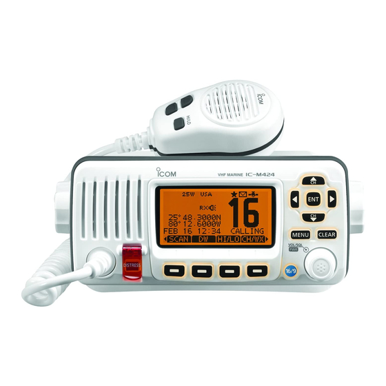
Page 12: Panel Description
PANEL DESCRIPTION ■ Front panel Speaker Function display (p. 5) r UP AND DOWN/CHANNEL SELECT KEYS [∫•CH]/[√•CH] Push to select the operating channels, Menu items, ➥ Menu settings, and so on. (pp. 14, 72) While scanning, push to check Favorite channels, ➥... - Page 13 Push to select a regular channel. Hold down for 1 second to select the Call channel. (p. ➥ * For only IC-M423 and IC-M423G except for Australian version transceivers. • “CALL” is displayed when the Call channel is selected. ➥ When the Call channel is selected, hold down for 3 sec- Public address [ ] (p.
- Page 14 PANEL DESCRIPTION ■ Front panel (Continued) Backlight [ ] (p. 18) Speaker Function display (p. 5) Push to enter the LCD and key backlight brightness ad- justment mode. • While in the adjustment mode, push [∫]/[√]/[Ω]/[≈] or rotate Dial to adjust the brightness of the LCD and key backlight. Log [ ] (p.
-
Page 15: Function Display
PANEL DESCRIPTION ■ Function display r CHANNEL GROUP ICON (p. 12) Shows which channel group is selected, INT, USA, ➥ CAN, ATIS or DSC, depending on the version. “WX” is displayed when the weather channel is select- ➥ ed.* *For only U.S.A. and Australian version transceivers. t CALL CHANNEL ICON (p. - Page 16 Shows the selected operating channel number. nected, and no time is manually entered. • When a simplex channel is selected, “A” is displayed. NOTE for the IC-M423 and IC-M424: !3 CHANNEL NAME FIELD These models do not come with a built-in GPS receiver.
-
Page 17: Softkey Function
PANEL DESCRIPTION ■ Softkey function !6 POSITION INDICATOR Various functions can be assigned to the softkeys. When a ➥ Shows the current position when position data is re- key function is assigned, the key icon is displayed above the ceived, or the position is manually entered. softkey, as shown below. -
Page 18: Speaker Microphone
➥ Speaker Microphone Lock function ON or OFF. (p. 17) * [HI/LO] is printed for the IC-M423/IC-M424. r CHANNEL 16/CALL CHANNEL KEY [16/C] ➥ Push to select Channel 16. (p. 11) ➥ Hold down for 1 second to select the Call channel. (p. -
Page 19: Preparation
PREPARATION Entering the MMSI code ■ The 9 digit MMSI (Maritime Mobile Service Identity: DSC self Repeat step e to enter all 9 digits. ID) code can be entered at power ON. After entering the 9 digit code, “FINISH” is automatically selected, and then push [ENT] or Dial to set it. -
Page 20: Entering The Atis Code (For Dutch And German Version Transceivers)
PREPARATION Entering the ATIS code ■ (For Dutch and German version transceivers) The 10 digit ATIS (Automatic Transmitter Identification Sys- Repeat step e to enter all 10 digits. tem) code can be entered at power ON. After entering the 10 digit code, “FINISH” is automatically selected, and then push [ENT] or Dial to set it. -
Page 21: Basic Operation
• Each channel group has an independent call channel after entry. erating channel. (p. 16) * [CHAN] is displayed instead of [CH/WX] for the IC-M423/IC- Push [CH/WX]* to return to the screen displayed before ➥ M423G except for Australian version. - Page 22 Channel group Rotate Dial or push [ ∫]/[√] to select the desired channel There are preset international channels in the IC-M423/IC- group, and then push [ENT]. M423G/IC-M424/IC-M424G. Except for the European ver- • U.S.A., (USA) International (INT), CAN (Canada), ATIS or DSC...
-
Page 23: Selecting A Weather Channel
BASIC OPERATION Selecting a Weather channel (For Only U.S.A. and Australian version transceivers) The transceiver has 10 weather channels. These are used for monitoring broadcasts from NOAA. (National Oceanographic and Atmospheric Administration) The transceiver can automatically detect a weather alert tone on the selected weather channel, or while scanning. -
Page 24: Receiving And Transmitting
BASIC OPERATION ■ Receiving and transmitting CAUTION: Transmitting without an antenna will damage Hold down [PTT] to transmit, then speak at your normal the transceiver. voice level. • “ ” is displayed. • Channel 70 cannot be used for transmission other than DSC. Hold down [PWR](Dial) to turn ON the power. -
Page 25: Adjusting The Volume And Squelch Levels
Push [ENT] to set the level, and exit the volume adjust- Microphone Microphone ment mode. • Push [CLEAR] to cancel. The desired function can be assigned to Dial. See page 77 IC-M423G/IC-M424G IC-M423/IC-M424 for details. -
Page 26: Entering A Call Channel Data
BASIC OPERATION ■ Entering a Call channel data Entering a Channel name ■ You can enter data in Call channel in each channel group for Enter a name of up to 10 characters. Capital letters, 0 to 9, some symbols, (! " # $ % & ' ( ) * + , – . quick recall. -
Page 27: Microphone Lock Function
This prevents accidental channel changes and function ac- cess. For only IC-M423G and IC-M424G. [HI/LO] is printed for the IC-M423 and IC-M424. While holding down [H/L] or [HI/LO] on the microphone, ➥ hold down [PWR](Dial) to turn ON the transceiver and turn Push [ Ω]/[≈]/[∫]/[√] to select “FINISH,”... -
Page 28: Adjusting The Backlight Level
BASIC OPERATION Adjusting the Backlight level Using the AquaQuake water ■ ■ draining function The function display and keys can be backlit for better visibil- ity under low light conditions. The AquaQuake water draining function clears water away The backlight is adjustable in 7 levels and OFF. from the speaker grill. -
Page 29: Scan Operation
SCAN OPERATION ■ Scan types Scanning is an efficient way to locate signals quickly over a Set the Favorite channels (scanned channel) before scan- wide frequency range. The transceiver has a Priority scan ning. Clear the Favorite channels which inconveniently stop and a Normal scan. -
Page 30: Setting Favorite Channels
SCAN OPERATION Setting Favorite channels ■ Starting a scan ■ For more efficient scanning, add desired channels as Favor- First, set the scan type (Priority or Normal scan) and scan ite channels, or clear the Favorite on unwanted channels. resume timer in the Menu screen. (p. 74) Channels that are not tagged will be skipped while scanning. -
Page 31: Dualwatch/Tri-Watch
DUALWATCH/TRI-WATCH Description Operation ■ ■ Dualwatch monitors Channel 16 while you are receiving Select Dualwatch or Tri-watch in the Menu screen. (p. 74) Y]/[Z] to select the desired operating channel. on another channel; Tri-watch monitors Channel 16 and the Push [ Call channel while receiving another channel. -
Page 32: Dsc Operation
DSC OPERATION DSC address ID ■ D Entering an Individual ID A total of 100 DSC address IDs can be entered and assigned After entering the 9 digit code, push [ENT] or Dial to set it. a name of up to 10 characters. •The ID name entry screen is displayed. - Page 33 DSC OPERATION D Entering a Group ID After entering the 9 digit code, push [ENT] or Dial to set it. Enter “GROUP ID” in the DSC SETTINGS menu. • Group ID name entry screen is displayed. ➪ DSC Settings ➪ Group ID...
- Page 34 DSC OPERATION ■ DSC address ID (Continued) D Deleting Individual and Group IDs Push [OK] to delete the ID, and return to the “INDIVIDUAL Enter “INDIVIDUAL ID” or “GROUP ID” in the DSC SET- ID” or “GROUP ID” list screen. TINGS menu.
-
Page 35: Entering Position And Time
DSC OPERATION Entering position and time ■ A Distress call should include the ship’s position and time. • Push [EXIT] to return to the normal operating mode. • Push [BACK] to return to the previous screen. If no GPS receiver is connected and built-in GPS receiver* is not receiving valid position data, your position and UTC (Universal Time Coordinated) time should be manually en- tered. -
Page 36: Making A Distress Call
DSC OPERATION ■ Making a Distress call A Distress call should be made if, in the opinion of the Master, After transmitting the call, the transceiver waits for an ac- that the ship or a person is in distress and requires immediate knowledgment call. - Page 37 DSC OPERATION Making a Regular call The Distress call confirmation screen is displayed. The nature of the Distress call should be included in the Dis- • Rotate Dial or push [Y]/[Z] to see the hidden lines. tress call. Enter “DISTRESS CALL” in the DSC CALLS menu. DSC Calls...
- Page 38 DSC OPERATION ■ Making a Distress call (Continued) When no GPS receiver is connected and built-in GPS re- After transmitting the call, the transceiver waits for an ac- ceiver* is not receiving valid position data, and both posi- knowledgment call. tion and time have been manually entered, the screen as •...
- Page 39 DSC OPERATION D Canceling a Distress call The Distress cancel call is transmitted. While waiting for an acknowledgment call, push [CAN- CEL]. Channel 16 is automatically selected. • Report your situation using the microphone. Push [CONTINUE]. • After the report, push [EXIT] to return to the normal operating •...
-
Page 40: Making Dsc Calls
DSC OPERATION Making DSC calls ■ To ensure correct operation of the DSC function, make About Manual Entry: sure you correctly set the CH70 SQL LEVEL. (p. 65) Enter a desired individual ID in the following way: • Select a desired number using Dial, or [Ω]/[≈]. D Making an individual call •... - Page 41 DSC OPERATION Select a desired intership channel using Dial or [ Y]/[Z], Standby on Channel 70 until an acknowledgement is re- then push [ENT]. ceived. • Intership channels are already preset into the transceiver in the recommended order. When the acknowledgement ‘Able to comply’ is received, alarm sounds and the screen below is displayed.
- Page 42 DSC OPERATION ■ Making DSC calls D Making an Individual Acknowledgement Making an Individual call (continued) Or, when the acknowledgement ‘Unable to comply’ is re- When you receive an Individual call, you can make an ac- ceived, alarm sounds and the screen below is displayed. knowledgement (‘Able to Comply,’...
- Page 43 DSC OPERATION Select one of three options, then push [ENT]. The Individual ACK confirmation screen is displayed. • Push [EXIT] to return to the normal operating mode. Push [CALL] to make an acknowledgement call. • Push [BACK] to return to the previous screen. The screens shown below are displayed.
- Page 44 DSC OPERATION Making a Group call ■ Making DSC calls Making an Individual Acknowledgement (continued) The Group call function allows you to make a DSC signal to Manual ACK: only a specific group. Enter “INDIVIDUAL ACK” in the DSC CALLS menu. Enter “GROUP CALL”...
- Page 45 DSC OPERATION Y]/[Z], A confirmation screen is displayed. Select a desired intership channel using Dial or [ then push [ENT]. • Confirm the call contents. • Intership channels are already preset into the transceiver in the recommended order. Push [CALL] to make a Group call. •...
- Page 46 DSC OPERATION ■ Making DSC calls (Continued) D Making an All Ships call A confirmation screen is displayed. • Confirm the call contents. All ships that have DSC transceiver use Channel 70 as their ‘listening channel.’ When you want to announce a message to these ships, use the ‘All Ships Call’...
- Page 47 DSC OPERATION D Making a Position Request Call About Manual Entry: (For only U.S.A. and Australian version transceivers) Enter a desired individual ID in the following way: Make a Position Request Call when you want to know a spe- • Select a desired number using Dial, or [Y]/[Z]/[Ω]/[≈]. cific ship’s current position, and so on.
- Page 48 DSC OPERATION ■ Making DSC calls Making a Position Request call (continued) Push [ALARM OFF] to stop the alarm, and then the screen Push [CALL] to make a Position Request Call. as shown below is displayed. • If Channel 70 is busy, the transceiver stands by until the channel becomes clear.
- Page 49 DSC OPERATION D Making a Position Report Call (For only U.S.A. and Australian version transceivers) About Manual Entry: Make a Position Report Call when you want to announce your Enter a desired individual ID in the following way: own position to a specific ship and receive an answer back. •...
- Page 50 DSC OPERATION ■ Making DSC calls Making a Position Report call (continued) Push [CALL] to make a Position Report Call. When no GPS receiver is connected and built-in GPS re- • If Channel 70 is busy, the transceiver stands by until the channel ceiver* is not receiving valid position data, and both position becomes clear.
- Page 51 DSC OPERATION Making a Polling Request Call (For only U.S.A. and Australian version transceivers) About Manual Entry: Make a Polling Request Call when you want to know a spe- Enter a desired individual ID in the following way: cific vessel is in the communication area, or not. •...
- Page 52 DSC OPERATION ■ Making DSC calls Making a Polling Request call (continued) Push [CALL] to make a Polling Request Call. Push [ALARM OFF] to stop the alarm, and then the screen • If Channel 70 is busy, the transceiver stands by until the channel as shown below is displayed.
- Page 53 DSC OPERATION D Making a Test call About Manual Entry: Testing on the exclusive DSC distress and safety calling Enter a desired address ID in the following way: channels should be avoided as much as possible. When test- • Select a desired number using Dial, or [Ω]/[≈]. ing on a distress or safety channel is unavoidable, you should •...
- Page 54 DSC OPERATION ■ Making DSC calls Making a Test call (continued) Push [CALL] to make a Test call. Push [ALARM OFF] to stop the alarm, and then the screen • If Channel 70 is busy, the transceiver stands by until the channel as shown below is displayed.
- Page 55 DSC OPERATION D Making a Test Acknowledgement call About Received call information: When the “TEST ACK” in DSC settings is set to ‘Auto TX’ • Push [EXIT] to return to the normal operating mode. (p. 63), the transceiver automatically transmits a reply call •...
- Page 56 DSC OPERATION ■ Making DSC calls Making a Test Acknowledgement call (continued) Manual ACK: Enter “TEST ACK” in the DSC CALLS menu. The Test ACK confirmation screen is displayed. Push [CALL] to make an acknowledgement call. ➪ DSC Calls ➪ Test ACK...
- Page 57 DSC OPERATION Making a Position Reply call About Received call information: Make a Position Reply call when a Position Request call is • Push [EXIT] to return to the normal operating mode. received. • Push [BACK] to return to the previous screen. When the “POSITION ACK”...
- Page 58 DSC OPERATION ■ Making DSC calls While transmitting the reply call, the screen shown below Making a Position Reply call (continued) is displayed, and then returns to the normal operating Manual Reply: mode. Enter “POSITION REPLY” in the DSC CALLS menu. ➪...
- Page 59 DSC OPERATION Making a Position Report Reply call About Received call information: • Push [EXIT] to return to the normal operating mode. Make a Position Report Reply call when a Position Report • Push [BACK] to return to the previous screen. call is received.
- Page 60 DSC OPERATION ■ Making DSC calls Making a Position Report Reply call (continued) Manual Reply: Enter “REPORT REPLY” in the DSC CALLS menu. The Position Report Reply call confirmation screen is dis- played. ➪ DSC Calls ➪ Position Report Reply MENU...
- Page 61 DSC OPERATION Making a Polling Request Reply call About Received call information: • Push [EXIT] to return to the normal operating mode. Make a Polling Request Reply call when a Polling Request • Push [BACK] to return to the previous screen. call is received.
- Page 62 DSC OPERATION ■ Making DSC calls Making a Polling Request Reply call (continued) Manual Reply: The Polling Request Reply call confirmation screen is dis- Enter “POLLING REPLY” in the DSC CALLS menu. played. Push [CALL] to make an acknowledgement call. ➪...
-
Page 63: Receiving Dsc Calls
DSC OPERATION Receiving DSC calls ■ D Receiving a Distress Call/Distress Acknowledgement [Example]: Receiving a Distress Call. When a Distress Call is received: [INFO] The emergency alarm sounds for 2 minutes. Push to display the Re- ➥ ➥ “RCVD DISTRESS” is displayed and the backlight blinks. ceived call information. - Page 64 DSC OPERATION ■ Receiving DSC calls (Continued) D Receiving a Distress Relay Call/Distress Relay Acknowledgement [Example]: Receiving a Distress Relay call. When a Distress Relay call is received: The emergency alarm sounds for 2 minutes. ➥ [INFO] “RCVD DISTRESS RELAY” is displayed and the backlight ➥...
-
Page 65: D Receiving An Individual Call
DSC OPERATION D Receiving an Individual Call [IGN] When an Individual Call is received: ➥ Push to ignore the Call and return to the normal operating ➥ The alarm sounds for 2 minutes. mode. “RCVD INDIVIDUAL CALL” is displayed. The backlight may ➥... - Page 66 DSC OPERATION ■ Receiving DSC calls (Continued) D Receiving a Group Call/Geographical Area Call/All Ships Call When a Group Call, Geographical Area Call, or All Ships Call [IGN] is received: The alarm sounds for 2 minutes. Push to ignore the Call and return to the normal operat- ➥...
-
Page 67: D Receiving A Position Request Call
DSC OPERATION D Receiving a Position Request Call [IGN] When a Position Request Call is received: ➥ Push to ignore the Call and return to the normal operat- ➥ The alarm sounds for 2 minutes. ing mode. ➥ “RCVD POS REQUEST” is displayed. The backlight blinks •... - Page 68 DSC OPERATION ■ Receiving DSC calls (Continued) D Receiving a Position Report Call [EXIT] When a Position Report Call is received: ➥ Push to ignore the Call and return to the normal operat- ➥ The alarm sounds for 2 minutes. ing mode.
- Page 69 DSC OPERATION D Receiving a Polling Request call/Test Call [IGN] [Example]: Receiving a Polling Request call. Push to ignore the Call and return to the normal operat- ➥ ing mode. When a Polling Request call is received: • The transceiver exits the DSC mode. The alarm sounds for 2 minutes.
-
Page 70: Transmitted Call Log
DSC OPERATION ■ Transmitted Call log ■ Receiving DSC calls (Continued) D Receiving a Test Acknowledgement Call When a Test Acknowledgement Call is received: The transceiver automatically stores up to 50 transmitted The alarm sounds for 2 minutes. ➥ calls, and the logs can be used as a supplement to your log- “RCVD TEST ACK”... -
Page 71: Received Call Log
DSC OPERATION ■ Received Call log The transceiver automatically stores up to 50 distress mes- Push [ Y]/[Z] to select the desired item, then push [ENT]. sages and 50 other messages, and they can be used as a supplement to your logbook. •... -
Page 72: D Other Messages
DSC OPERATION ■ Received Call log (Continued) Other messages Rotate Dial to scroll the DSC message contents. Push [LOG] to enter “RCVD CALL LOG” in the DSC CALLS • The stored message has various information, depending on the menu, or you can enter it through the Menu screen. DSC call type. -
Page 73: Dsc Settings
DSC OPERATION ■ DSC Settings D Position Entry Rotate Dial to select “Auto TX” or “Manual TX,” then push (See page 25) D Add Individual ID/Group ID [ENT]. (See pages 22, 23) • Push [BACK] to cancel and return to the DSC Settings menu. D Delete Individual ID/Group ID (See page 24) D Automatic Acknowledgement... -
Page 74: Dsc Operation
DSC OPERATION ■ DSC Settings (Continued) D Channel 16 Switch function Auto (No Delay): After receiving a Distress call, and By regulation, after receiving a Distress call, the transceiv- [ACPT] is pushed on the confirmation er changes the operating channel to Channel 16. However, screen, the transceiver immediately when this setting is set to “OFF,”... -
Page 75: [Ent]
DSC OPERATION D Alarm D Channel 70 Squelch level Set the Alarm function ON or OFF, depending on the Cat- Set the squelch level on Channel 70. egory or Status. The transceiver has 11 squelch levels between 1 (loose squelch) and 10 (tight squelch) and OPEN. q Enter “ALARM”... -
Page 76: (Push [Menu].) (Rotate Dial, Then Push [Ent].)
DSC OPERATION ■ DSC Settings (Continued) D DSC Loop Test The DSC loop test function sends transmit DSC signals to the receive AF circuit to compare and check the TX and RX signals at the AF level. q Enter “DSC LOOP TEST” in the DSC Settings menu. ➪... -
Page 77: Making An Individual Call Using An Ais Transponder
DSC OPERATION Making an Individual call using an AIS transponder ■ When the optional MA-500TR CLASS B AIS TRANSPON- DER is connected to your transceiver, an individual DSC call can be transmitted to a selected AIS target, without needing to enter the target’s MMSI code. In this case, the call type is automatically set to Routine. - Page 78 DSC OPERATION ■ Making an Individual call using an AIS transponder (Continued) After making the individual DSC call, the transponder will ‘Able to comply’ is received display “DSC Transmission COMPLETED.” • Push [CLEAR] to return to the screen displayed before you en- tered the voice channel selection screen in step w.
-
Page 79: Other Functions
OTHER FUNCTIONS Using the Intercom ■ The optional Intercom function allows you to talk between the After releasing [INCM CALL], hold down [PTT] and speak radio and the where the Command microphone is located. into the microphone at your normal voice level. The optional HM-195 is required for •... -
Page 80: Using The Rx Speaker
OTHER FUNCTIONS Using the RX Speaker Using the PA (Public Address) ■ ■ The RX Speaker function enables you to hear the received The transceiver has a PA function to make announcements audio through a PA speaker. through a PA speaker. Connect a PA speaker as described on page 82. -
Page 81: Using The Horn
OTHER FUNCTIONS Using the Horn ■ The Horn function sounds a horn. Connect a PA speaker as described on page 82. Push [HORN] to enter the Horn mode. Hold down [HORN] to sound a horn. • While holding down [HORN], the horn sounds, and the screen below is displayed. -
Page 82: Menu Screen Operation
MENU SCREEN OPERATION ■ Using the Menu screen Entering the Menu screen The Menu screen is used for entering infrequently changed values, function settings or making DSC calls. In addition to this page, see pages 73 through 81 for details. Example: Set the channel group to “USA”... -
Page 83: Menu Screen Items
MENU SCREEN OPERATION ■ Menu screen items Radio Settings Item Ref. Item Ref. The Menu screen contains the following items. • Scan Type p. 74 • CHAN Group p. 74 • Scan Timer p. 74 • WX Alert* p. 75 DSC Calls •... -
Page 84: Radio Settings Items
MENU SCREEN OPERATION Radio Settings items ■ Scan type Dual/Tri-watch The transceiver has two scan types, Normal scan and Prior- This item can be selected as Dualwatch or Tri-watch. (p. 21) ity scan. A Normal scan searches all Favorite channels in the (Default: Dualwatch) selected channel group. - Page 85 MENU SCREEN OPERATION D Weather alert (For only U.S.A. and Australian version transceivers) A NOAA broadcast station transmits a weather alert tone be- fore important weather information. After the transceiver detects the alert, “WX ” blinks until the transceiver is operated. •...
-
Page 86: Configuration Items
You can turn OFF beep tones for silent operation, or you can turn ON the tones to have confirmation beeps sound when a key is pushed. (Default: ON) For “Dial” assignment For “Softkeys” assignment* * [CHAN] is displayed instead of [CH/WX] for the IC-M423 and IC-M423G except for Australian version. - Page 87 Repeatedly pushing Dial sequentially displays all the func- tions in the order they are assigned, and skips any functions assigned as Not Used. * [CHAN] is displayed instead of [CH/WX] for the IC-M423 and IC- M423G except for Australian version.
- Page 88 MENU SCREEN OPERATION ■ Configuration items (Continued) • RX D UTC Offset Turn the receive Noise Cancel function ON or OFF. Set the offset time between the UTC (Universal Time Coordi- OFF : Turns OFF the function. (Default) nated) and your local time to between –14:00 and +14:00 (in : The Noise Cancel function reduces random noise com- 1 minute steps).
-
Page 89: Inactivity Timer
MENU SCREEN OPERATION D Inactivity Timer • Not DSC Related Set the inactivity timer to between 1 and 10 minutes (in 1 When the LCD displays a screen other than the normal opera- minute steps) or OFF for a “Not DSC Related” item, and set tion screen, or one not related to the DSC, and no key opera- it to between 1 and 15 minutes (in 1 minute steps) or OFF tion occurs for this set period, the transceiver automatically... -
Page 90: Nmea Output
MENU SCREEN OPERATION ■ Configuration items (Continued) D NMEA Output • DSC data output (Default: OFF) Select the Data Output function option for a NMEA output When receiving a DSC call, this function makes the trans- port. ceiver send the DSC data from its NMEA Output port to an external device. - Page 91 MENU SCREEN OPERATION D Remote ID Set a Remote ID number to between 1 and 69. The Remote ID is included in the sentence of the Icom origi- nal NMEA format. (Default: 15) D COMMANDMIC Speaker (Displayed only when the optional HM-195 is connected.) The HM-195’s external speaker can be used instead of the...
-
Page 92: Connections And Maintenance
CONNECTIONS AND MAINTENANCE ■ Connections Green: Listener B (Data-L), NMEA Out (–) Yellow: Listener A (Data-H), NMEA Out (+) Connect to NMEA Out lines of a GPS receiver for position- data. • A NMEA 0183 ver. 2.0 or later RMC, GGA, GNS, GLL, VTG, GSV, and GSA sentence format compatible GPS receiver is re- quired. - Page 93 CONNECTIONS AND MAINTENANCE Connect to the MA-500TR r DC POWER CONNECTOR Connect the transceiver to the high-density D-Sub 15-pin Connects to a 13.8 V DC power source. connector of the MA-500TR using the OPC-2014* cable. Af- ter connecting, an Individual DSC call can be made to the CAUTION: After connecting the DC power cable, NMEA AIS target using the transponder without entering the target’s leads, external speaker leads, and PA speaker leads, cov-...
-
Page 94: Antenna
CONNECTIONS AND MAINTENANCE ■ Antenna ■ Supplied accessories A key element in the performance of any communication sys- Mounting bracket For mounting bracket tem is the antenna. Ask your dealer about antennas and the best place to mount them. Knob bolts Flat washers (M5) ■... -
Page 95: Mounting The Transceiver
CONNECTIONS AND MAINTENANCE ■ Mounting the transceiver Using the supplied mounting bracket • MOUNTING EXAMPLE Built-in GPS receiver The universal mounting bracket supplied with your transceiv- is located here. er allows overhead or dashboard mounting. (For only IC-M423G and IC-M424G.) Mount the bracket securely to a surface which is more than 10 mm thick and can support more than 5 kg using the two supplied screws (5 ×... -
Page 96: Installation
CONNECTIONS AND MAINTENANCE ■ MB-132 installation An optional MB-132 is available for mounting the Attach the clamps on either side of the transceiver with two flush mount transceiver to a flat surface, such as an instrument panel. M5 × 8 mm supplied bolts. •... -
Page 97: Microphone Installation
CONNECTIONS AND MAINTENANCE ■ Microphone installation Using the mounting base as a template, carefully mark the holes where the cable and three screws will be fastened. Drill holes at these marks. Install the mounting base using the supplied screws, as shown below. - Page 98 CONNECTIONS AND MAINTENANCE Mounting base Gasket...
-
Page 99: Specifications And Options
IC-M423 (CHN version) 156.050–162.025 MHz • Sensitivity: CH70 156.525 MHz IC-M423/IC-M423G –5 dBµ emf typical (at 20 dB SINAD) • Mode: 16K0G3E (FM) IC-M424/IC-M424G –13 dBµ typical (at 12 dB SINAD) 16K0G2B (DSC) DSC IC-M423/IC-M423G –4 dBµ emf typical (1% BER) •... -
Page 100: Options
Approved Icom optional equipment is designed for optimal perfor- mance when used with an Icom transceiver. Icom is not responsible for the destruction or damage to an Icom transceiver in the event the Icom transceiver is used with equipment 180 (7.1) 25.3... -
Page 101: Channel List
CHANNEL LIST Channel number Frequency (MHz) Channel number Frequency (MHz) Channel number Frequency (MHz) Channel number Frequency (MHz) USA* CAN* Transmit Receive USA* CAN* Transmit Receive USA* CAN* Transmit Receive USA* CAN * Transmit Receive 156.050 160.650 157.050 161.650 156.375 156.375 157.325 161.925 156.425 156.425 157.325 157.325... -
Page 102: Troubleshooting
TROUBLESHOOTING PROBLEM POSSIBLE CAUSE SOLUTION REF. The transceiver does • Bad connection to the power source. • Check the connection to the transceiver and p. 82 not turn ON. power source. Little or no sound comes • Squelch level is set too high. •... -
Page 103: Template
TEMPLATE 180 (7 ⁄ 165.1 (6 ⁄ ⁄ R12 (Max.) HM-195 MB-132 29.5 to 31.5 (d) ⁄ to 1 ⁄ Unit: mm (inch) -
Page 105: Index
INDEX Cleaning ................84 COMMANDMIC Speaker ............81 Accessories, supplied ............84 Connections ................82 Acknowledgement, Automatic ..........63 Country Code List ..............ii Alarm ................65 All Ships call Making a call ..............36 Receiving a Call ..............56 Display contrast ..............76 Antenna ................84 Distress Acknowledgement ..........53 AquaQuake .................18 Distress Call ATIS code ................10... - Page 106 INDEX Geographical Area Call ............56 Key Assignment ..............76 Group call Key Beep ................76 Making a call ..............34 Receiving a Call ..............56 Group ID MB-132 installation .............86 Entering ID ..............23 Menu screen Deleting ID ..............24 Menu screen items ............73 Using the Menu screen ..........72 Microphone installation ............87 Microphone Lock function ...........17 Horn...
- Page 107 INDEX Softkey function ..............7 Specifications ..............89 PA (Public Address) ............70 Speaker Microphone ............8 Polling Request Call Squelch ................15 Making a call ..............41 Making a reply call ............51 Receiving a call ..............59 Position and time ..............25 Test Acknowledgement call Position Report Call Making a call ..............45 Making a call ..............39 Receiving a call ..............60...
- Page 108 < Intended Country of Use > A-7197D-1EX Printed in Japan 2014 Icom Inc. © 1-1-32 Kamiminami, Hirano-ku, Osaka 547-0003, Japan Printed on recycled paper with soy ink.
Need help?
Do you have a question about the ic-m423 and is the answer not in the manual?
Questions and answers