Icom IC-M423 Instruction Manual
Vhf marine transceiver
Hide thumbs
Also See for IC-M423:
- Instruction manual (108 pages) ,
- Service manual (47 pages) ,
- Instruction manual (108 pages)
Table of Contents
Advertisement
Quick Links
Advertisement
Table of Contents

Subscribe to Our Youtube Channel
Related Manuals for Icom IC-M423


Summary of Contents for Icom IC-M423
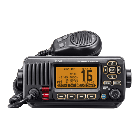
- Page 1 INSTRUCTION MANUAL VHF MARINE TRANSCEIVER iM423...
-
Page 2: Explicit Definitions
IC-M423. We appreciate you making the IC-M423 your radio of choice, and hope you agree with Icom’s philosophy of “technology EXPLICIT DEFINITIONS first.” Many hours of research and development went into the de sign of your IC-M423. -
Page 3: In Case Of Emergency
IN CASE OF EMERGENCY INSTALLATION NOTE If your vessel requires assistance, contact other vessels and The installation of this equipment should be made in such a the Coast Guard by sending a Distress call on Channel 16. manner as to respect the EC recommended electromagnetic field exposure limits (1999/519/EC). - Page 4 * Except for the DC power connector, NMEA In/Out leads and AF direct sunlight, such as the dashboard. Out leads. Icom, Icom Inc. and the Icom logo are registered trademarks of Icom Incor- porated (Japan) in Japan, the United States, the United Kingdom, Germany, France, Spain, Russia and/or other countries.
-
Page 5: Table Of Contents
COUNTRY CODE LIST TABLE OF CONTENTS • ISO 3166-1 FOREWORD ................. i IMPORTANT ................i Country Codes Country Codes EXPLICIT DEFINITIONS ............i Austria Liechtenstein IN CASE OF EMERGENCY ..........ii Belgium Lithuania INSTALLATION NOTE ............ii Bulgaria Luxembourg PRECAUTIONS ..............iii Croatia Malta Czech Republic... - Page 6 TABLE OF CONTENTS (Continued) Adjusting the volume level ..........14 PA (Public Address) function ........67 ■ ■ Adjusting the squelch level .........14 Horn function ..............68 ■ ■ Adjusting the display backlight level ......15 ■ 9 MENU SCREEN OPERATION ........69−75 AquaQuake water draining function ......15 ■...
-
Page 7: Operating Rules
OPERATING RULES Priorities (2) OPERATOR’S LICENSE A Restricted Radiotelephone Operator Permit is the license • Read all rules and regulations pertaining to call priorities, most often held by small vessel radio operators when a radio and keep an up-to-date copy handy. Safety and distress is not required for safety purposes. -
Page 8: Front Panel
PANEL DESCRIPTION Front panel ■ Speaker Function display (p. 4) r UP AND DOWN/CHANNEL SELECT KEYS [∫•CH]/[√•CH] Push to select the operating channels, Menu items, ➥ Menu settings, and so on. (pp. 11, 69) Push to check Favorite channels, change the scanning ➥... - Page 9 PANEL DESCRIPTION i CHANNEL 16/CALL CHANNEL KEY [16/C] RX Speaker [ ] (p. 67) Push to select Channel 16. (p. 9) ➥ Push to turn the RX Speaker mode ON or OFF. Hold down for 1 second to select the Call channel. (p. 9) ➥...
-
Page 10: Function Display
PANEL DESCRIPTION Function display ■ t CALL CHANNEL ICON (p. 9) Appears when the Call channel is selected. y DUPLEX ICON (p. 10) Appears when a duplex channel is selected. u FAVORITE CHANNEL ICON (p. 17) Appears when a Favorite (Tag) channel is selected. i MESSAGE ICON (p. -
Page 11: Panel Description
PANEL DESCRIPTION !4 KEY ICON (p. 6) !6 POSITION INDICATOR Shows the programmed function of the softkeys on the ➥ Shows the current position when a GPS receiver is front panel. connected, or the position is manually programmed. • When the GPS position is invalid, “??” may blink every 2 sec- !5 TIME ZONE INDICATOR onds instead of position. -
Page 12: Speaker Microphone 6
PANEL DESCRIPTION Speaker Microphone Softkey function ■ ■ Various functions can be assigned to the softkeys. When the key function is assigned, the key icon is displayed Microphone above the softkey, as shown below. Speaker Softkey function selection When “ Ω”... -
Page 13: Mmsi Code Programming
PREPARATION MMSI code programming ■ The 9 digit MMSI (Maritime Mobile Service Identity: DSC self Repeat step e to enter all 9 digits. ID) code can be programmed at power ON. After entering the 9 digit code, “FINISH” is automatically selected, and then push [ENT] or Dial to set it. - Page 14 PREPARATION ATIS code programming ■ (For Dutch and German version transceivers) The 10 digit ATIS (Automatic Transmitter Identification Sys- Repeat step e to enter all 10 digits. tem) code can be programmed at power ON. After entering the 10 digit code, “FINISH” is automatically selected, and then push [ENT] or Dial to set it.
-
Page 15: Channel Selection
BASIC OPERATION Channel selection ■ Channel 16 Call channel Channel 16 is the distress and safety channel. It is used for Each regular channel group has a separate leisure use Call establishing initial contact with a station and for emergency channel. - Page 16 There are preprogrammed international channels for the Rotate Dial or push [ ∫]/[√] to select the desired channel IC-M423. For U.K. transceiver versions, there are prepro- group, and then push [ENT]. grammed U.S.A. channels in addition to International chan- • U.S.A., (USA) International (INT), ATIS or DSC channel groups may be selected, depending on the version.
-
Page 17: Important
BASIC OPERATION Receiving and transmitting ■ CAUTION: Transmitting without an antenna will damage IMPORTANT: To maximize the readability of your transmit- the transceiver. ted signal, pause a few seconds after pushing [PTT], hold the microphone 5 to 10 cm from your mouth and speak at Hold down [PWR](Dial) to turn ON the power. -
Page 18: Call Channel Programming
BASIC OPERATION Call channel programming Channel name programming ■ ■ You can program the Call channel with your most often-used Each channel can be assigned a unique alphanumeric ID of channel in each channel group for quick recall. up to 10 characters. Capital letters, 0 to 9, some symbols (! "... -
Page 19: Microphone Lock Function
BASIC OPERATION Microphone Lock function ■ Repeat step e to input all characters. The Microphone Lock function electrically locks [∫], [√] and the [HI/LO] keys on the supplied microphone. This prevents accidental channel changes and function access. While holding down [HI/LO] on the microphone, hold down ➥... -
Page 20: Adjusting The Volume Level
BASIC OPERATION Adjusting the volume level Adjusting the squelch level ■ ■ The volume level can be adjusted with [VOL/SQL](Dial). The squelch level can be adjusted with [VOL/SQL](Dial). In order to receive signals properly, as well as for the scan Rotate [VOL/SQL](Dial), or push [VOL/SQL](Dial) one or to function effectively, the squelch must be adjusted to the more times to display the volume adjustment screen. -
Page 21: Adjusting The Display Backlight Level
BASIC OPERATION Adjusting the display AquaQuake water draining ■ ■ backlight level function The function display and keys can be backlit for better visibil- The AquaQuake water draining function clears water away ity under low light conditions. from the speaker grill. Without this function, water may muffle The backlight is adjustable in 7 levels and OFF. -
Page 22: Scan Operation
SCAN OPERATION Scan types ■ Scanning is an efficient way to locate signals quickly over a Set the Favorite channels (scanned channel) before scan- wide frequency range. The transceiver has a Priority scan ning. Clear the Favorite channels which inconveniently stop and a Normal scan. -
Page 23: Setting Favorite Channels
SCAN OPERATION Setting Favorite channels Starting a scan ■ ■ For more efficient scanning, add desired channels as Favor- First, set the scan type (Priority or Normal scan) and scan ite channels, or clear the Favorite on unwanted channels. resume timer in the Menu screen. (p. 71) Channels that are not tagged will be skipped while scanning. -
Page 24: Dualwatch/Tri-Watch
DUALWATCH/TRI-WATCH Description Operation ■ ■ Dualwatch monitors Channel 16 while you are receiving Select Dualwatch or Tri-watch in the Menu screen. (p. 71) Y](CH) or [Z](CH) to select the desired operating on another channel; Tri-watch monitors Channel 16 and the Push [ Call channel while receiving another channel. -
Page 25: Dsc Operation
DSC OPERATION DSC address ID ■ Programming Individual ID A total of 100 DSC address IDs can be programmed and as- After entering the 9 digit code, push [ENT] or Dial to set it. signed a name of up to 10 characters. •... -
Page 26: D Programming Group Id
DSC OPERATION Programming Group ID Enter “GROUP ID” in the DSC SETTINGS menu. After entering the 9 digit code, push [ENT] or Dial to set it. • Group ID name programming screen is displayed. ➪ DSC Settings ➪ Group ID MENU... - Page 27 DSC OPERATION Deleting Individual/Group ID Enter “INDIVIDUAL ID” or “GROUP ID” in the DSC SET- Push [OK] to delete the ID, and return to the “INDIVIDUAL TINGS menu. ID” or “GROUP ID” list screen. • Push [CANCEL] to cancel it. ➪...
-
Page 28: Position And Time Programming
DSC OPERATION Position and time programming ■ A Distress call should include the ship’s position and time. If no GPS is connected, your position and UTC (Universal Time Coordinated) time should be manually input. They are auto- matically included when a GPS receiver compatible with the NMEA0183 ver. -
Page 29: Distress Call
DSC OPERATION Distress call ■ A Distress call should be transmitted if, in the opinion of the After transmitting the call, the transceiver waits for an ac- Master, the ship or a person is in distress and requires im- knowledgment call. mediate assistance. -
Page 30: D Regular Call
DSC OPERATION Regular call The nature of the Distress call should be included in the Dis- Hold down [DISTRESS] for 3 seconds to transmit the Dis- tress call. tress call. • While holding down [DISTRESS], count down beeps sound and both the key and display backlighting blink. - Page 31 DSC OPERATION When no GPS receiver is connected, and both position After transmitting the call, the transceiver waits for an ac- and time have been manually programmed, the screen as knowledgment call. shown below appears. Edit your latitude and longitude po- •...
- Page 32 DSC OPERATION Distress cancel call While waiting for an acknowledgment call, push [CAN- The Distress cancel call is transmitted. CEL]. Channel 16 is automatically selected. Push [CONTINUE]. • Report your situation using the microphone. • After the report, push [EXIT] to return to the normal operating •...
-
Page 33: Transmitting Dsc Calls
DSC OPERATION Transmitting DSC calls About Manual Inputting: ■ Enter a desired individual ID in the following way: • Select a desired number using Dial, or [Ω]/[≈]. To ensure correct operation of the DSC function, make • Push [ENT] or Dial to set it. sure you correctly set the CH70 SQL LEVEL. - Page 34 DSC OPERATION Transmitting an Individual call (continued) Y](CH)/ Select a desired intership channel using Dial or [ Standby on Channel 70 until an acknowledgement is re- [Z](CH), then push [ENT]. ceived. • Intership channels are already preset into the transceiver in the recommended order.
- Page 35 DSC OPERATION Or, when the acknowledgement ‘Unable to comply’ is re- ceived, beeps sound and the screen below is displayed. Push [ALARM OFF] to stop the beeps. Then push [EXIT] to return to the operating channel (before you entered the MENU screen).
- Page 36 DSC OPERATION Transmitting an Individual Acknowledgement When receiving an Individual call, you can transmit an ac- Select one of three options, then push [ENT]. knowledgement (‘Able to Comply,’ ‘Propose New Channel’ or ‘Unable to Comply’) by using the on-screen prompts (Quick ACK.) Also, you can send an acknowledgement through the MENU system (Man ual ACK.) Quick ACK:...
- Page 37 DSC OPERATION The Individual ACK confirmation screen is displayed. Manual ACK: Push [CALL] to transmit an acknowledgement call. Enter “INDIVIDUAL ACK” in the DSC CALLS menu. ➪ DSC Calls ➪ Individual ACK MENU (Push [MENU]) (Rotate Dial, then push [ENT].) •...
-
Page 38: D Transmitting A Group Call
DSC OPERATION Transmitting a Group call The Group call function allows you to transmit a DSC signal About Manual Inputting: to only a specific group. Enter a desired group ID in the following way: • Select a desired number using Dial, or [Ω]/[≈]. •... - Page 39 DSC OPERATION Push [CALL] to transmit the Group call. • If Channel 70 is busy, the transceiver stands by until the channel becomes clear. After the Group call has been transmitted, the following screen is displayed. Announce the information using the microphone. After the announcement, push [EXIT] to return to the nor- mal operating mode.
-
Page 40: D Transmitting An All Ships Call
DSC OPERATION Transmitting an All Ships call All ships, that have DSC transceiver, use Channel 70 as their A confirmation screen appears. ‘listening channel.’ When you want to announce a message to • Confirm the call contents. these ships within range, use the ‘All Ships Call’ function. Enter “ALL SHIPS CALL”... -
Page 41: D Transmitting A Test Call
DSC OPERATION Transmitting a Test call Testing on the exclusive DSC distress and safety calling chan- About Manual Inputting: nels should be avoided as much as possible. When testing on Enter a desired address ID in the following way: a distress/safety channel is unavoidable, you should indicate •... - Page 42 DSC OPERATION Transmitting a Test call (continued) Push [CALL] to transmit the Test call. Push [ALARM OFF] to stop the beeps, and then the screen • If Channel 70 is busy, the transceiver stands by until the channel as shown below is displayed. becomes clear.
-
Page 43: D Transmitting A Test Acknowledgement Call
DSC OPERATION Transmitting a Test Acknowledgement call When the “TEST ACK” in DSC settings is set to ‘Auto TX’ The Test ACK confirmation screen is displayed. (p. 60), the transceiver automatically transmits a reply call Push [CALL] to transmit the acknowledgement call. when receiving a Test call. - Page 44 DSC OPERATION Transmitting a Test Acknowledgement call (continued) Manual ACK: Enter “TEST ACK” in the DSC CALLS menu. The Test ACK confirmation screen is displayed. Push [CALL] to transmit the acknowledgement call. ➪ DSC Calls ➪ Test ACK MENU (Push [MENU]) (Rotate Dial, then push [ENT].) •...
-
Page 45: D Transmitting A Position Reply Call
DSC OPERATION Transmitting a Position Reply call • Push [INFO] to display the Position Request call information. Transmit a Position Reply call when a Position Request call Push [BACK] to return to the previous screen, or push [ACK]. is received. When the “POSITION ACK”... - Page 46 DSC OPERATION Transmitting a Position Reply call (continued) While transmitting the reply call, the screen shown below Manual Reply: is displayed, and then returns to the normal operating Enter “POSITION REPLY” in the DSC CALLS menu. mode. ➪ DSC Calls ➪...
- Page 47 DSC OPERATION Transmitting a Position Report Reply call Transmit a Position Report Reply call when a Position Report • Push [INFO] to display the Position Report Request call informa- tion. Request call is received. Push [BACK] to return to the previous screen, or push [ACK]. Quick Reply: When a Position Report Request call is received, beeps sound and the screen as shown below is displayed.
- Page 48 DSC OPERATION Transmitting a Position Report Reply call (continued) Manual Reply: Enter “POSITION REPORT REPLY” in the DSC CALLS The Position Report Reply call confirmation screen is dis- menu. played. Push [CALL] to transmit the acknowledgement call. ➪ DSC Calls ➪...
-
Page 49: D Transmitting A Polling Reply Call
DSC OPERATION Transmitting a Polling Reply call Transmit a Polling Reply call when a Polling Request call is • Push [INFO] to display the Polling Request call information. Push [BACK] to return to the previous screen, or push [ACK]. received. When the “POSITION ACK”... - Page 50 DSC OPERATION Manual Reply: Enter “POLLING REPLY” in the DSC CALLS menu. While transmitting the reply call, the screen shown below is displayed, and then returns to the normal operating ➪ DSC Calls ➪ Polling Reply MENU mode. (Push [MENU]) (Rotate Dial, then push [ENT].) •...
-
Page 51: Receiving Dsc Calls
DSC OPERATION Receiving DSC calls ■ [INFO] Receiving a Distress Call ➥ Push to display the Received call information. (p. 57) When a Distress Call is received: The emergency alarm sounds for 2 minutes. ➥ “RCVD DISTRESS” pops up and the LCD backlight ➥... - Page 52 DSC OPERATION Receiving a Distress Acknowledgement When a Distress Acknowledgement sent to another ship is [INFO] received: ➥ Push to display the Received call information. (p. 57) The emergency alarm sounds for 2 minutes. ➥ “RCVD DISTRESS ACK” pops up and the LCD backlight ➥...
-
Page 53: D Receiving A Distress Relay Call
DSC OPERATION Receiving a Distress Relay Call When a Distress Relay call is received: [INFO] The emergency alarm sounds for 2 minutes. ➥ Push to display the Received call information. (p. 57) ➥ “RCVD DISTRESS RELAY” pops up and the LCD back- ➥... - Page 54 DSC OPERATION Receiving a Distress Relay Acknowledgement When a Distress Relay Acknowledgement is received: [INFO] The emergency alarm sounds for 2 minutes. ➥ Push to display the Received call information. (p. 57) ➥ “RCVD DIST RELAY ACK” pops up and the LCD backlight ➥...
-
Page 55: D Receiving An Individual Call
DSC OPERATION Receiving an Individual Call When an Individual Call is received: [IGN] ➥ The alarm sounds for 2 minutes. ➥ Push to ignore the Call and return to the normal operating ➥ “RCVD INDIVIDUAL CALL” pops up. The LCD backlight mode. -
Page 56: D Receiving A Group Call
DSC OPERATION Receiving a Group Call When a Group Call is received: [IGN] ➥ The alarm sounds for 2 minutes. ➥ Push to ignore the Call and return to the normal operat- ➥ “RCVD GROUP CALL” pops up. The LCD backlight may ing mode. -
Page 57: D Receiving An All Ships Call
DSC OPERATION Receiving an All Ships Call When an All Ships Call is received: [IGN] ➥ The alarm sounds for 2 minutes. ➥ Push to ignore the Call and return to the normal operat- ➥ “RCVD ALL SHIPS CALL” pops up. The LCD backlight may ing mode. -
Page 58: Receiving A Geographical Area Call
DSC OPERATION Receiving a Geographical Area Call When a Geographical Area Call (for the area you are in) is [IGN] received: ➥ Push to ignore the Call and return to the normal operat- ➥ The alarm sounds for 2 minutes. ing mode. -
Page 59: D Receiving A Position Request Call
DSC OPERATION Receiving a Position Request Call When a Position Request Call is received: [IGN] ➥ The alarm sounds for 2 minutes. ➥ Push to ignore the Call and return to the normal operat- ➥ “RCVD POS REQUEST” pops up. The LCD backlight ing mode. - Page 60 DSC OPERATION Receiving a Position Report Call When a Position Report Call is received: [EXIT] ➥ The alarm sounds for 2 minutes. ➥ Push to ignore the Call and return to the normal operat- ➥ “RCVD POSITION REPORT” pops up. The LCD backlight ing mode.
-
Page 61: D Receiving A Polling Request Call
DSC OPERATION D Receiving a Polling Request call [IGN] When a Polling Request call is received: ➥ The alarm sounds for 2 minutes. ➥ Push to ignore the Call and return to the normal operat- ing mode. ➥ “RCVD POLLING REQUEST” pops up. The LCD backlight blinks for 2 minutes. -
Page 62: D Receiving A Test Call
DSC OPERATION D Receiving a Test Call [IGN] When a Test Call is received: ➥ Push to ignore the Call and return to the normal operat- ➥ The alarm sounds for 2 minutes. ing mode. ➥ “RCVD TEST CALL” pops up. The LCD backlight blinks for •... -
Page 63: Received Call Log
DSC OPERATION Received Call log Receiving a Test Acknowledgement Call ■ When a Test Acknowledgement Call is received: ➥ The alarm sounds for 2 minutes. The transceiver automatically stores up to 50 distress mes- ➥ “RCVD TEST ACK” pops up. The LCD backlight blinks for sages and 50 other messages, and they can be used as a 2 minutes. - Page 64 DSC OPERATION Received Call log (Continued) ■ Other messages Push [ Y] or [Z] to select the desired item, then push [ENT]. Push [LOG] to enter “RCVD CALL LOG” in the DSC CALLS • The message in the unopened file has not been read. menu, or you can enter it through the Menu screen.
-
Page 65: Transmitted Call Log
DSC OPERATION Transmitted Call log ■ Rotate Dial to scroll the DSC message contents. • The stored message has various information, depending on the The transceiver automatically stores up to 50 transmitted DSC call type. calls, and the logs can be used as a supplement to your log- book. -
Page 66: Dsc Settings
DSC OPERATION DSC Settings ■ D Position Input Rotate Dial to select “Auto TX” or “Manual TX,” then push (See page 22) D Add Individual ID/Group ID [ENT]. (See pages 19, 20) • Push [BACK] to cancel and return to the DSC Settings menu. D Delete Individual ID/Group ID (See page 21) Automatic Acknowledgement... -
Page 67: Channel 16 Switch Function
DSC OPERATION Channel 16 Switch function By regulation, after receiving a Distress call, the transceiv- Auto (No Delay) : After receiving a Distress call, and er switches the operating channel to Channel 16. However, [ACPT] is pushed on the confirmation when this setting is set to “OFF,”... -
Page 68: D Dsc Data Output
DSC OPERATION DSC Data Output Alarm Select an option for the DSC Data Output function. Set the Alarm function ON or OFF, depending on the Cat- When receiving a DSC call, this function makes the trans- egory or Status. ceiver send the DSC data from its NMEA Output port to a connected device. - Page 69 DSC OPERATION D Channel 70 Squelch level D DSC Loop Test Set the squelch level on Channel 70. The DSC loop test function sends transmit DSC signals to The transceiver has 11 squelch levels between 1 (loose the receive AF circuit to compare and check the TX and RX squelch) and 10 (tight squelch) and OPEN.
-
Page 70: Making An Individual Call Using An Ais Transponder
DSC OPERATION Making an Individual call using an AIS transponder ■ When the optional MA-500TR CLASS B AIS TRANSPONDER connected to your transceiver, an individual DSC call can be transmitted to a selected AIS target, without needing to enter the target’s MMSI code. In this case, the call type is automati- cally set to Routine. -
Page 71: Dsc Operation
DSC OPERATION After making the individual DSC call, the transponder will ‘Able to comply’ is received display “DSC Transmission COMPLETED.” • Push [CLEAR] to return to the screen displayed before you en- tered the voice channel selection screen in step w. •... -
Page 72: Other Functions
OTHER FUNCTIONS Intercom operation ■ The optional Intercom function allows you to talk between the After releasing [INCM CALL], hold down [PTT] and speak deck and the cabin. The optional HM-195 into the microphone at a normal voice level. command micro is required for Intercom operation. -
Page 73: Rx Speaker Function
OTHER FUNCTIONS RX Speaker function PA (Public Address) function ■ ■ The RX Speaker function enables you to hear the received The transceiver has a PA function to make announcements audio on the deck or bridge through a PA speaker. through a PA speaker. -
Page 74: Horn Function
OTHER FUNCTIONS Horn function ■ The Horn function sounds a horn. Connect a PA speaker as described on page 76. Push [HORN] to enter the Horn mode. Hold down [HORN] to sound a horn. • While holding down [HORN], the horn sounds, and the screen below is displayed. -
Page 75: Menu Screen Operation
MENU SCREEN OPERATION ■ Menu screen operation Entering the Menu screen and operation The Menu screen is used for programming infrequently changed values, function settings or sending DSC calls. In addition to this page, see pages 70 through 75 for details. Example: Set the channel group to “USA.”... -
Page 76: Menu Screen Items
MENU SCREEN OPERATION Menu screen items ■ Configuration The Menu screen contains the following items. Item Ref. Item Ref. DSC Calls • Backlight p. 72 • Noise Cancel p. 74 Item Ref. Item Ref. • Display Contrast p. 72 • Inactivity Timer p. -
Page 77: Radio Settings Items
MENU SCREEN OPERATION Radio Settings items ■ Scan type Dual/Tri-watch (Default: Priority Scan) (Default: Dualwatch) The transceiver has two scan types; Normal scan and Priority This item can be selected as Dualwatch or Tri-watch. (p. 18) scan. A Normal scan searches all Favorite channels in the selected channel group. -
Page 78: Configuration Items
MENU SCREEN OPERATION Configuration items Key Assignment ■ Desired functions can be assigned to Dial and the softkeys. Backlight When the “KEY ASSIGNMENT” screen is displayed, rotate (Default: 7) Dial or push [∫]/[√] to select “Dial” or “Softkeys,” and then The function display and keys can be backlit for better visibil- push [ENT]. - Page 79 MENU SCREEN OPERATION Push [EXIT] to exit the Menu screen. • Softkeys assignment • Push [CLEAR] or [BACK] to return to the previous screen. The desired function can be assigned as the softkey func- tion. The assigned function can be used when its key icon is •...
-
Page 80: Inactivity Timer
MENU SCREEN OPERATION Noise Cancel • TX Set the Noise Cancel function for both receive and transmit. (Default: OFF) Turn the transmit Noise Cancel function ON or OFF. When the “NOISE CANCEL” screen is displayed, rotate Dial OFF : Turns OFF the function. or push [Y]/[Z] to select “RX”... -
Page 81: Menu Screen Operation
Set a Remote ID number to between 1 and 69. eration screen, or one not related to the DSC, and no key The Remote ID is included in the sentence of the Icom origi- operation occurs for this set period, the transceiver automati- nal NMEA format. -
Page 82: Connections And Maintenance
CONNECTIONS AND MAINTENANCE Connections ■ Green: Listener B (Data-L) Connects to an NMEA Out Negative line of a GPS receiver for position data. • A NMEA0183 ver. 2.0 or 3.01 RMC, GGA, GNS, GLL and VTG sentence format compatible GPS receiver is required. Ask your dealer about suitable GPS receivers. - Page 83 CONNECTIONS AND MAINTENANCE Connect to the MA-500TR r DC POWER CONNECTOR Connect the transceiver to the high-density D-Sub 15-pin Connects to a 13.8 V DC power source. connector of the MA-500TR using the OPC-2014* cable. Af- ter connecting, an Individual DSC call can be made to the CAUTION: After connecting the DC power cable, NMEA AIS target using the transponder without entering the target’s leads, external speaker leads and PA speaker leads, cover...
-
Page 84: Antenna
CONNECTIONS AND MAINTENANCE Antenna Supplied accessories ■ ■ A key element in the performance of any communication sys- Mounting bracket For mounting bracket tem is the antenna. Ask your dealer about antennas and the best place to mount them. Knob bolts Flat washers (M5) Fuse replacement Screws (5×20 mm) -
Page 85: Mounting The Transceiver
CONNECTIONS AND MAINTENANCE Mounting the transceiver ■ Using the supplied mounting bracket The universal mounting bracket supplied with your transceiv- • OVERHEAD MOUNTING er allows overhead or dashboard mounting. Mount the bracket securely to a surface which is more than 10 mm thick and can support more than 5 kg using the 2 supplied screws (5 ×... -
Page 86: Installation
CONNECTIONS AND MAINTENANCE MB-132 installation ■ An optional MB-132 is available for mounting the Attach the clamps on either side of the transceiver with 2 flush mount transceiver to a flat surface, such as an instrument panel. M5 × 8 mm supplied bolts. •... -
Page 87: Microphone Installation
CONNECTIONS AND MAINTENANCE Microphone installation ■ Using the mounting base as a template, carefully mark the holes where the cable and three screws will be fastened. Drill holes at these marks. Install the mounting base using the supplied screws, as shown below. - Page 88 CONNECTIONS AND MAINTENANCE Mounting base Gasket...
-
Page 89: Specifications And Options
SPECIFICATIONS AND OPTIONS Specifications ■ General Receiver • Frequency coverage : Tx 156.000–161.450 MHz • Receive system : Double conversion Rx 156.000–163.425 MHz superheterodyne • Mode : FM (16K0G3E), • Sensitivity (20 dB SINAD) : –5 dBµ emf (typical) DSC (16K0G2B) •... -
Page 90: Options
Approved Icom optional equipment is designed for optimal perfor- mance when used with an Icom transceiver. Icom is not responsible for the destruction or damage to an Icom transceiver in the event the Icom transceiver is used with equipment that is not manufactured or approved by Icom. -
Page 91: Channel List
CHANNEL LIST • International channels Frequency (MHz) Frequency (MHz) Frequency (MHz) Frequency (MHz) Frequency (MHz) Frequency (MHz) Transmit Receive Transmit Receive Transmit Receive Transmit Receive Transmit Receive Transmit Receive 156.050 160.650 156.550 156.550 157.050 161.650 156.075 160.675 156.575 156.575 157.075 161.675 156.100 160.700... -
Page 92: Channel List
CHANNEL LIST • USA channels (for U.K. version only) Frequency (MHz) Frequency (MHz) Frequency (MHz) Frequency (MHz) Frequency (MHz) Frequency (MHz) Transmit Receive Transmit Receive Transmit Receive Transmit Receive Transmit Receive Transmit Receive 156.050 156.050 156.600 156.600 157.100 157.100 156.225 156.225 75 * 156.775... -
Page 93: Template
TEMPLATE 165.1 R12 (Max.) HM-195 MB-132 29.5 to 31.5 (d) Unit: mm... -
Page 95: Troubleshooting
TROUBLESHOOTING PROBLEM POSSIBLE CAUSE SOLUTION REF. The transceiver does • Bad connection to the power supply. • Check the connection to the transceiver and p. 76 not turn ON. power supply. Little or no sound comes • Squelch level is set too high. •... - Page 96 < Intended Country of Use > A-7012D-1EU-w Printed in Japan 2012 Icom Inc. © 1-1-32 Kamiminami, Hirano-ku, Osaka 547-0003, Japan Printed on recycled paper with soy ink.
Need help?
Do you have a question about the IC-M423 and is the answer not in the manual?
Questions and answers