Icom IC-M424 Quick Start Manual
Hide thumbs
Also See for IC-M424:
- Service manual (47 pages) ,
- Instruction manual (110 pages) ,
- Instruction manual (110 pages)
Advertisement
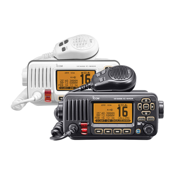
IC-M424
VHF MARINE TRANSCEIVER
OPC-980
Programming
Adapter Cable
TO ANTENNA
*
1
OPC-478UC
Programming
Cable
OPC-1541
20ft of cable
*
2
*
1
*
2
HI/LO
OPC-1540
20ft of cable
Wires For Standard
External Speaker (4 )
DC Power Connector
+ (Red)
– (Black)
AF Out Leads
Orange: Public Address Speaker (+)
Gray: Public Address Speaker (–)
Blue: External Speaker (+)
Black: External Speaker (–)
NMEA Leads
Brown: Out- Talker B (Data-L) (–)
White: Out+Talker A (Data-H) (+)
Green: In- Listener B (Data-L) (–)
Yellow: In+ Listener A (Data-H) (+)
HM-196
Handset
(non-removable)
MIC
* For more details about connections please review
©2015 Icom America Inc. The Icom logo is a registered
HM-195
COMMANDMICIV™
Handset
pages 83 & 84 in the Instruction Manual.
1 Represents the NMEA In/Out Leads.
2 Represents the AF Out Leads.
trademark of Icom Inc. 42070
Advertisement
Table of Contents

Subscribe to Our Youtube Channel
Related Manuals for Icom IC-M424


Summary of Contents for Icom IC-M424
- Page 1 * For more details about connections please review pages 83 & 84 in the Instruction Manual. 1 Represents the NMEA In/Out Leads. 2 Represents the AF Out Leads. ©2015 Icom America Inc. The Icom logo is a registered trademark of Icom Inc. 42070...
- Page 2 12421 Willows Rd NE Kirkland, WA Connecting a GPS to Your Icom M324/M424 radio On the back panel of your radio, there is a connector with four colors: brown, white, green, and yellow. The yellow and green wires connect to your GPS.
- Page 3 Kirkland, WA Raymarine GPS Note: When using some Raymarine equipment you may need to connect your Icom radio directly to the Raymarine GPS itself, not through a repeated port from other equipment, such as a plotter. This ensures that the proper NMEA sentence passes to the radio.
- Page 4 • Have a technician check the plotter/GPS using test equipment to verify it is sending the GPS sentence. • Check the solder points on the radio and plotter connectors. Some connectors are very small, increasing the likelihood of solder bridging. Page 4 ©2015 Icom America Inc.
Need help?
Do you have a question about the IC-M424 and is the answer not in the manual?
Questions and answers