Table of Contents
Advertisement
Advertisement
Table of Contents

Related Manuals for Icom IC-M421


Summary of Contents for Icom IC-M421
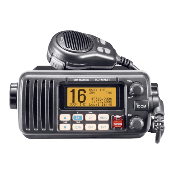
- Page 1 INSTRUCTION MANUAL VHF MARINE TRANSCEIVER iM421...
-
Page 2: Important
IC-M421. We want to take a couple of moments of your time to thank you for making the IC-M421 your radio of choice, and hope you agree with Icom’s philosophy of “technology first.” Many EXPLICIT DEFINITIONS hours of research and development went into the design of your IC-M421. -
Page 3: In Case Of Emergency
IN CASE OF EMERGENCY INSTALLATION NOTE If your vessel requires assistance, contact other vessels and The installation of this equipment should be made in such a the Coast Guard by sending a distress call on Channel 16. manner as to respect the EC recommended electromagnetic field exposure limits (1999/519/EC). -
Page 4: Doc
CE versions of the IC-M421 which display the This warning symbol indicates that this equip- “CE” symbol on the serial number seal, com- ment operates in non-harmonised frequency ply with the essential requirements of the Eu- bands and/or may be subject to licensing condi-... -
Page 5: Table Of Contents
TABLE OF CONTENTS FOREWORD …………………………………………………………… i 6 DSC OPERATION …………………………………………… 14–44 I MMSI code programming……………………………………… 14 IMPORTANT …………………………………………………………… i I MMSI code check ……………………………………………… 15 EXPLICIT DEFINITIONS ……………………………………………… i I DSC individual ID ……………………………………………… 16 IN CASE OF EMERGENCY…………………………………………… ii I Position and time programming ………………………………... -
Page 6: Precaution
PRECAUTION RWARNING! NEVER AVOID the use of chemical agents such as benzine or al- connect the transceiver to an AC cohol when cleaning, as they may damage the transceiver outlet. This may pose a fire hazard or result in an electric surfaces. -
Page 7: Operating Rules
OPERATING RULES D D PRIORITIES (2) OPERATOR’S LICENSE A Restricted Radiotelephone Operator Permit is the license • Read all rules and regulations pertaining to priorities and most often held by small vessel radio operators when a radio keep an up-to-date copy handy. Safety and distress calls is not required for safety purposes. -
Page 8: Panel Description
PANEL DESCRIPTION I Panel description Function Speaker display (p. 4) q POWER/VOLUME CONTROL [VOL] (p. 8) e DISTRESS KEY [DISTRESS] (p. 22) ➥ Rotate to turn the transceiver power ON or OFF. Transmits a distress call when pushed for 5 sec. ➥... - Page 9 PANEL DESCRIPTION y SCAN/TAG CHANNEL KEY [SCAN•TAG] (p. 13) o CHANNEL/DUALWATCH/TRI-WATCH KEY [CH•DUAL] ➥ Push to start and stop the normal or priority scan when ➥ Push to select the regular channel. (pgs. 6, 7) ➥ Push for 1 sec. to start dualwatch or tri-watch. (p. 11) tag channels are programmed.
-
Page 10: I Function Display
PANEL DESCRIPTION I Function display r DUPLEX INDICATOR (p. 7) Appears when a duplex channel is selected. • Duplex channel has a different transmit frequency and receiving BUSY-INT---- frequency. 25W-DUP-TAG- t CHANNEL GROUP INDICATOR (p. 7) NORMAL-SCAN- Indicates whether an International “INT” or U.S.A. “USA” 23 34.154N- channel is selected. -
Page 11: I Microphone
PANEL DESCRIPTION I Microphone o TIME ZONE INDICATOR ➥ Shows the current time data when a GPS receiver is connected. ➥ “No Time” appears when no GPS receiver is con- nected and no time data is input manually. ➥ “Local” appears when the offset time data is set. Microphone (p. -
Page 12: Basic Operation
BASIC OPERATION I Channel selection D D Channel 16 D D Call channel Channel 16 is the distress and safety channel. It is used for Each regular channel group has a separate leisure-use call establishing initial contact with another station and for emer- channel. - Page 13 BASIC OPERATION International channels and U.S.A. channels* International channel The IC-M421 is pre-programmed with 57 International (INT) -INT---- channels in addition to 59 U.S.A. channels*. These channel 25W-DUP-TAG- groups may be specified for the operating area. 23 34.154N- q Push [CH•DUAL] to select a regular channel.
-
Page 14: I Receiving And Transmitting
BASIC OPERATION I Receiving and transmitting CAUTION: Transmitting without an antenna may damage IMPORTANT: To maximize the readability of your trans- the transceiver. mitted signal, pause a few sec. after pushing [PTT], hold the microphone (M) 5 to 10 cm from your mouth and speak q Rotate [VOL] to turn power ON. -
Page 15: I Call Channel Programming
BASIC OPERATION I Call channel programming r Push [L] or [M] to se- You can program the call channel with your most often-used -INT---- 25W- -TAG- channel in each channel group for quick recall. lect the desired chan- CALL WRITE - CALL WRITE nel. -
Page 16: I Channel Comments
BASIC OPERATION I Channel comments I Microphone lock function Memory channels can be labelled with alphanumeric com- The microphone lock function electrically locks [Y]/[Z] and ments of up to 10 characters each for easy channel recogni- [HI/LO] keys on the supplied microphone. This prevents ac- tion. -
Page 17: Dualwatch/Tri-Watch
DUALWATCH/TRI-WATCH I Description I Operation q Select Dualwatch or Tri-watch in set mode. (p. 46) Dualwatch monitors Channel 16 while you are receiving an- w Push [L] or [M] to select the desired operating channel. other channel; tri-watch monitors Channel 16 and the call e Push [CH•DUAL] for 1 sec. -
Page 18: Scan Operation
SCAN OPERATION I Scan types Scanning is an efficient way to locate signals quickly over a Set the tag channels (scanned channel) before scanning. wide frequency range. The transceiver has priority scan and Clear the tag channels which inconveniently stop scanning, normal scan. -
Page 19: I Setting Tag Channels
SCAN OPERATION I Setting tag channels I Starting a scan For more efficient scanning, add the desired channels as tag Set scan type (priority or normal scan) and scan resume timer channels or clear the tag for unwanted channels. in advance using set mode. (p. 45) Channels are not tagged will be skipped during scanning. -
Page 20: Dsc Operation
DSC OPERATION I MMSI code programming u Push [L] or [M] to set the specific 9-digit MMSI code. The 9-digit MMSI (Maritime Mobile Service Identity: DSC self • Push [CH•DUAL] or [16•C] to move the cursor forward or back- ID) code can be programmed at power ON. ward, respectively. -
Page 21: I Mmsi Code Check
DSC OPERATION I MMSI code check t Push [CLR] or [M] to select “Exit,” push [ENT]. The 9-digit MMSI (DSC self ID) code can be checked. • Returns to the DSC menu. q Push [MENU] to enter the DSC menu. •... -
Page 22: I Dsc Individual Id
DSC OPERATION I DSC individual ID 1st digit ‘0’ is fixed for a group ID. When you input 1st digit ‘0’ A total of 100 DSC address IDs can be programmed and and other 8 digits, the ID is automatically registered as a group named with up to 10 characters. - Page 23 DSC OPERATION D D Deleting address ID q Push [MENU] to enter the DSC menu. r Push [L] or [M] to select the desired ID name for delet- w Push [L] or [M] to select “Set up,” and push [ENT]. ing.
- Page 24 DSC OPERATION D D Programming Group ID q Push [MENU] to enter the DSC menu. --DSC Menu-- w Push [L] or [M] to select “Set up,” and push [ENT]. Add:Group ID Input 8 digits --DSC Menu-- 0________ Select Item Polling Request ≤...
- Page 25 --DSC Menu-- --DSC Menu-- Select ID Select Item Office Polling Request ≤ Icom Received Calls ˘Station A ≥ Distress Setting <CLR˘Exit / ENT˘OK> ˘Set up ≥ t Push [ENT] to delete the group ID and returns to the set e Push [L] or [M] to select “DEL:Group ID,”...
-
Page 26: I Position And Time Programming
DSC OPERATION I Position and time programming e The position information appears. Set your latitude data A distress call should include the ship’s position and time data. If no GPS is connected, your position and UTC (Univer- using [L] or [M]. After setting the latitude data, push [ENT] sal Time Coordinated) time should be input manually. -
Page 27: I Position And Time Indication
• Push [SCAN•TAG] to clear the UTC time data. A GPS receiver appropriate for the IC-M421 is not supplied • Push [CLR] to cancel and exit the condition to the DSC menu. from Icom. A GPS receiver with NMEA0183 ver. 2.0 or 3.01 format is required for position indication. -
Page 28: I Distress Call
DSC OPERATION I Distress call e After transmitting the distress call, the transceiver waits for A distress call should be transmitted, if in the opinion of the Master, the ship or a person is in distress and requires imme- an acknowledgment call on Ch 70. diate assistance. - Page 29 DSC OPERATION ➥ A distress alert contains (default); D D Normal call • Nature of distress: Undesignated distress The nature of the distress call should be included in the dis- • Position data : GPS or manual input position data held for tress call.
- Page 30 DSC OPERATION t After setting the longitude data, push [ENT] to set the cur- When a GPS receiver (NMEA0183 ver. 2.0 or 3.01) is con- nected, next steps r, t (Current position/time program- rent UTC time using [L] or [M], then push [ENT]. ming) do not appear.
-
Page 31: I Transmitting Dsc Calls
DSC OPERATION I Transmitting DSC calls i After receiving the acknowledgment, reply using the mi- crophone. D D Transmitting an individual call The individual call function allows you to transmit a DSC sig- RCV DTRS ACK nal to a specific ship only. <Osaka Bay <CLR˘... - Page 32 DSC OPERATION r Push [L] or [M] to select a desired intership channel or y Standby on Channel 70 until an acknowledgement is re- “Manual Input,” push [ENT]. ceived. • Intership channels are already preset into the transceiver in rec- --DSC Menu-- ommending order.
- Page 33 DSC OPERATION D D Transmitting an individual acknowledgement r Push [L] or [M] to select that you can comply to the call or When receiving an individual call, you can transmit an ac- not from “Able to Comply” or “Unable to Com- knowledgement (‘Able to comply’...
- Page 34 --DSC Menu-- Group Call Select Address TX Completed Manual Input ˘Office Icom ≥ <CLR˘Exit> <CLR˘Exit / ENT˘OK> u Push [CLR] to exit the condition and selects the specified r Push [L] or [M] to select a desired intership channel or intership channel in step r automatically.
- Page 35 DSC OPERATION D D Transmitting an all ships call r Push [ENT] to transmit the all ships call. Large ships use Channel 70 as their ‘listening channel.’ When • Channel 70 is selected and the all ships call is transmitted. you want to announce a message to these ships, use the all ships call function.
-
Page 36: D Transmitting A Position Request Call
DSC OPERATION D D Transmitting a position request call r Push [ENT] to transmit the position request call. Transmit a position request call when you want to know a • If Channel 70 is busy, the transceiver stands by until the channel specific ship’s current position, etc. - Page 37 DSC OPERATION D D Transmitting a position report call When a GPS receiver (NMEA0183 ver. 2.0 or 3.01) is con- Transmit a position report call when you want to announce nected, next steps r, t (Current position/time program- your own position to a specific ship and to get an answer, etc. ming) do not appear.
- Page 38 DSC OPERATION t After setting the longitude data, push [ENT] to set the time u After the position report call has been transmitted, the fol- information appears. Set the current UTC time with [L] or lowing indication is displayed. [M], then push [ENT]. --DSC Menu-- •...
- Page 39 DSC OPERATION D D Transmitting a polling request call r Push [ENT] to transmit the polling request call. Transmit a polling request call when you want to know a spe- • If Channel 70 is busy, the transceiver stands by until the channel cific ship is in the communication area, etc.
-
Page 40: D Transmitting A Position Reply Call
DSC OPERATION D D Transmitting a position reply call When a GPS receiver (NMEA0183 ver. 2.0 or 3.01) is con- Transmit a position reply call when a position request call is nected, next steps r, t (Current position/time program- received. ming) do not appear. - Page 41 DSC OPERATION D D Transmitting a position report reply call t After setting the longitude data, push [ENT] to set the time Transmit a position report reply call when a position report call information appears. Set the current UTC time with [L] or is received.
- Page 42 DSC OPERATION D D Transmitting a polling reply call r Push [ENT] to transmit the polling request call to the se- Transmit a polling reply call when a polling request call is re- lected station. ceived. q Push [MENU] to enter the DSC menu. w Push [L] or [M] to select “Polling Reply,”...
-
Page 43: I Receiving Dsc Calls
DSC OPERATION I Receiving DSC calls D D Receiving a distress call D D Receiving a distress acknowledgement While monitoring Channel 70 and a distress call is received: While monitoring Channel 70 and a distress acknowledge- ➥ The emergency alarm sounds for 2 minutes. ment to other ship is received: ➥... - Page 44 [CLR] to ignore the group call. for voice communication (depending on your replying con- dition see p. 27 for individual acknowledgement call proce- dure for details.); push [CLR] to ignore the individual call. RCV GROUP <Icom <CLR˘ SAFETY Beep Off> RCV INDV <Paul...
- Page 45 DSC OPERATION D D Receiving a geographical area call D D Receiving a position request call While monitoring Channel 70 and a geographical area call While monitoring Channel 70 and a position request call is re- (for the area you are in) is received: ceived: ➥...
- Page 46 DSC OPERATION D D Receiving a polling request call D D Receiving a position report reply call While monitoring Channel 70 and a polling request call is re- While monitoring Channel 70 and a position report reply call ceived: is received: ➥...
-
Page 47: I Received Messages
DSC OPERATION I Received messages w Push [L] or [M] to scroll to the desired message, push The transceiver automatically stores up to 20 distress mes- sages and 20 other messages. The messages can be used [ENT]. as an assistance to the logbook. •... - Page 48 DSC OPERATION D D Other messages e Push [L] or [M] to scroll the message. q Push [L] or [M] to select “Other,” push [ENT]. • The stored message has various information and depending on --DSC Menu-- the type of distress call. Select Message Distress --DSC Menu--...
-
Page 49: I Dsc Set Mode
DSC OPERATION I DSC Set mode r Set the offset time from the UTC (Universal Time Coordi- D D MMSI code check (See p. 15 for detail) nated) time using [L] or [M]. D D Add Address ID (See p. 16 for detail) •... - Page 50 DSC OPERATION D D Automatic acknowledgement r Push [L] or [M] to turn the automatic acknowledgement This item sets the automatic acknowledgement function ON function ON or OFF. or OFF. When a position request, position report or polling request call --DSC Menu-- is received, transceiver automatically transmits a position re- Auto ACK...
-
Page 51: Set Mode
SET MODE I Set mode programming I Set mode items Set mode is used to change the conditions of the trans- D D Scan type ceiver’s functions: scan type (normal or priority), scan resume The transceiver has 2 scan types: normal scan and priority timer, dual/tri-watch, transceiver’s beep tone, backlight and scan. - Page 52 SET MODE D D Dual/Tri-watch D D Backlight Select the watch function from Dualwatch or tri-watch. (p. 11) The LCD backlight level can be adjusted from OFF, Min (dark), Mid and Max (bright). --Set Mode-- Dual/Tri --Set Mode-- Tri-watch Backlight ˘Dualwatch ˘Max <ENT˘OK>...
-
Page 53: Connections And Maintenance
CONNECTIONS AND MAINTENANCE I Supplied accessories I Antenna The following accessories are supplied: A key element in the performance of any communication sys- tem is an antenna. Ask your dealer about antenna and the best place to mount them. I Fuse replacement One fuse is installed in the supplied DC power cable. -
Page 54: I Connections
CONNECTIONS AND MAINTENANCE I Connections r ANTENNA CONNECTOR Connects a marine VHF antenna with a PL-259 connector to the transceiver. CAUTION: Transmitting without an antenna may dam- age the transceiver. CAUTION: After connecting the DC power cable, GPS re- ceiver jack and external speaker jack, cover the connector and jacks with an adhesive tape as shown below, to pre- vent water seeping into the transceiver. -
Page 55: I Mounting The Transceiver
CONNECTIONS AND MAINTENANCE I Mounting the transceiver D D Using the supplied mounting bracket EXAMPLE The universal mounting bracket supplied with your transceiver allows overhead or dashboard mounting. • Mount the transceiver securely with the 2 supplied screws (5 × 20) to a surface which is more than 10 mm thick and can support more than 5 kg. -
Page 56: I Optional Mb-69 Installation
CONNECTIONS AND MAINTENANCE I Optional MB-69 installation e Attach the clamps on either side of the transceiver with 2 An optional MB-69 is available for mounting the FLUSH MOUNT supplied bolts (5 × 8 mm). transceiver to a flat surface such as an instrument panel. •... -
Page 57: Troubleshooting
TROUBLESHOOTING PROBLEM POSSIBLE CAUSE SOLUTION REF. The transceiver does • Bad connection to the power supply. • Check the connection to the transceiver. p. 48 not turn ON. No sound from speaker. • Squelch level is too high. • Set squelch to the threshold point. p. -
Page 58: Channel List
CHANNEL LIST • International channels Frequency (MHz) Frequency (MHz) Frequency (MHz) Frequency (MHz) Frequency (MHz) Frequency (MHz) Transmit Receive Transmit Receive Transmit Receive Transmit Receive Transmit Receive Transmit Receive 156.050 160.650 156.550 156.550 157.050 161.650 156.075 160.675 156.575 156.575 157.075 161.675 156.100 160.700... - Page 59 CHANNEL LIST • USA channels (for U.K. version only) Frequency (MHz) Frequency (MHz) Frequency (MHz) Frequency (MHz) Frequency (MHz) Frequency (MHz) Transmit Receive Transmit Receive Transmit Receive Transmit Receive Transmit Receive Transmit Receive 01A 156.050 156.050 156.600 156.600 22A 157.100 157.100 64A 156.225 156.225...
-
Page 60: Specifications And Option
SPECIFICATIONS AND OPTION I Specifications Specifications are measured in accordance with EN301 025. D D Receiver D D General • Receive system : Double conversion superheterodyne • Frequency coverage • Sensitivity (20 dB SINAD) : –2 dBµ emf typical Transmit 156.000–161.450 MHz (CH 70 receiver) –2 dBµ... -
Page 61: Template
TEMPLATE R8 (Max.) Unit: mm... -
Page 63: Dimensions
Dimensions Unit: mm 28.3 111.2 14.2... - Page 64 < Intended Country of Use > A-6380D-1EU Printed in Japan 1-1-32 Kamiminami, Hirano-ku, Osaka 547-0003, Japan 2004 Icom Inc. ©...
Need help?
Do you have a question about the IC-M421 and is the answer not in the manual?
Questions and answers