Christie CP2230 Setup Manual
Hide thumbs
Also See for CP2230:
- User manual (178 pages) ,
- Service manual (151 pages) ,
- Installation and setup manual (19 pages)
Table of Contents
Advertisement
Quick Links
Advertisement
Table of Contents

Subscribe to Our Youtube Channel
Related Manuals for Christie CP2230


Summary of Contents for Christie CP2230
- Page 1 CP2230 S e t u p G u i d e 020-100515-04...
- Page 3 CP2230 S E T U P G U I D E 020-100515-04...
- Page 4 Performance specifications are based on information available at the time of printing. Christie makes no warranty of any kind with regard to this material, including, but not limited to, implied warranties of fitness for a particular purpose. Christie will not be liable for errors contained herein or for incidental or consequential damages in connection with the performance or use of this material.
-
Page 7: Table Of Contents
4.7 Adjust Top and Bottom Boresight....................4-4 4.8 Adjust Top and Bottom Boresight with an ILS................4-5 4.9 Adjust DMD Convergence ......................4-5 4.10 Fold Mirror Adjustment......................4-6 4.11 Calibrate the System ........................4-7 4.12 Color Calibration ........................4-7 CP2230 Setup Guide 020-100515-04 Rev. 1 (05-2014) - Page 8 7.8 Cannot Establish Communication with the cinema projector .............7-2 7.9 Blank Screen, No Display of Cinema Image ................7-3 7.10 Severe Motion Artifacts......................7-3 7.11 Image Appears Vertically Stretched or ‘Squeezed’ into Center of Screen........7-3 7.12 No Image, Just Pink Snow ......................7-3 CP2230 Setup Guide 020-100515-04 Rev. 1 (05-2014)
- Page 9 7.21 The Upper Portion of the Display is Waving, Tearing, or Jittering .........7-5 7.22 Portions of the Display are Cut OFF or Warped to the Opposite Edge........7-5 7.23 Display Appears Compressed (Vertically Stretched) ...............7-5 7.24 Inconsistent Picture Quality.......................7-5 CP2230 Setup Guide 020-100515-04 Rev. 1 (05-2014)
-
Page 11: Labels And Markings
1 Introduction This manual is intended for professionally trained operators of Christie high-brightness projection systems. These operators are qualified to replace the lamp and air filter, but should not attempt to install or service the cinema projector. Only accredited Christie technicians who are knowledgeable about the hazards associated with high-voltage, ultraviolet exposure, and the high temperatures generated by the cinema projector lamp are authorized to assemble, install, and service the cinema projector. -
Page 12: Ac / Power Precautions
2) Use only an AC power cord recommended by Christie. DO NOT attempt operation if the AC supply and cord are not within the specified voltage and power range. Use only the attachments and/or accessories recommended by Christie. Use of others may result in the risk of fire, shock or personal injury. -
Page 13: Contacting Your Dealer
Contacting Your Dealer If you encounter a problem with your Christie cinema projector, contact your dealer. To assist with the servicing of your cinema projector, enter the information in the tables and keep this information with your records. -
Page 15: 2: Installation And Setup
2 Installation and Setup This section provides information and procedures for positioning and installing the cinema projector. Site Requirements To safely install and operate the CP2230 cinema projector, the installation location must meet these minimum requirements: • Physical Operating Environment •... -
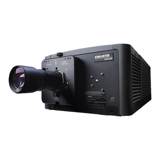
Page 16: Cinema Projector Components
Provides access to the lamp. The lamp door must remain closed and locked for normal operation. Lamp replacement should only be performed by qualified technicians. The cinema projector is designed to operate with 2.0kW and 3.0kW lamps. CP2230 Setup Guide 020-100515-04 Rev. 1 (05-2014) -
Page 17: Projection Lens
• PIB Faceplate Connections: • Ethernet: Use the 10Base-T/100Base-TX Ethernet port for network connection to the cinema projector. • GPIO: Connect external I/O devices, such as the Christie ACT, for remote control of a limited number of cinema projector functions. - Page 18 GREEN, active source present. Lamp Power Supply (LPS) The Lamp Power Supply (LPS) (P/N 127-101103-01) is an optional accessory for the CP2230 cinema projector. To connect it to the cinema projector, you use two high-current lamp leads, a RS-232 serial cable and an Interlock (Lamp Enable) cable.
-
Page 19: Installation Safety And Warning Guidelines
NOTE: Unlike film cinema projectors, it is best to keep the cinema projector lens surface as parallel to the screen as possible, even if significantly above the screen center. When a particularly short throw distance CP2230 Setup Guide 020-100515-04 Rev. 1 (05-2014) - Page 20 4. Install and secure the lamp power supply (LPS) in the rack stand: a. Remove the right side panel of the rack stand. b. Remove the cross bar. Figure 2-3 Side View of Rack Stand CP2230 Setup Guide 020-100515-04 Rev. 1 (05-2014)
- Page 21 Secure the airflow duct to the rack stand using the screws from the rack stand panels. j. Wire all of the components in the rack stand and replace the side panel. Keep Clear Figure 2-5 CP2230 Setup Guide 020-100515-04 Rev. 1 (05-2014)
-
Page 22: Secure The Cinema Projector
Make sure several threads are engaged into the cinema projector’s baseplate. The CP2230 lens should be centered and parallel with the screen. This orientation ensures optimum lens performance with minimal offset. If this position is not possible (such as when the cinema projector is significantly higher than the center of the screen), it is better to rely on offset rather than extra tilt. -
Page 23: Install The Touch Panel Controller (Tpc)
2. Tighten the mounting arm until it fits tightly on the joint. Figure 2-9 3. Connect the cable from the TPC to the connector on the rear panel of the cinema projector. 4. Adjust the angle of the TPC. CP2230 Setup Guide 020-100515-04 Rev. 1 (05-2014) -
Page 24: Connect External Exhaust Ducting
Add an extractor or a booster if there is insufficient airflow. Do not mount the extractor on the cinema projector as this may introduce some vibration into the image. NOTE: To prevent the cinema projector from overheating 2-10 CP2230 Setup Guide 020-100515-04 Rev. 1 (05-2014) -
Page 25: Install The Primary Lens
3. With the UP label facing up, insert the lens straight into the lens mount opening all the way back, without turning. 4. Move the lens clamp to the DOWN position to lock the lens assembly. Lock Clamp Locked Figure 2-13 Lock Lens In Place CP2230 Setup Guide 2-11 020-100515-04 Rev. 1 (05-2014) - Page 26 Installation and Setup 5. Remove the front lens cap. 6. On the TPC, tap Menu > Configuration > Diagnostics and Calibration. 7. Tap Reference Calibration. 2-12 CP2230 Setup Guide 020-100515-04 Rev. 1 (05-2014)
-
Page 27: Install The Optional Anamorphic Lens
4. Adjust yaw so the clearance between both lens barrels is equal from side-to-side. 2.13 Install the Lamp This procedure should only be performed by a Christie accredited technician. DANGER High-pressure lamp may explode if improperly handled. Always wear approved protective safety clothing whenever lamp door is open or when handling the lamp. - Page 28 Installation and Setup 6. Install the anode yoke assembly. Use this table to determine the correct position of the anode yoke assembly: Table 2.2 Lamp Types Available for CP2230 and Anode Yoke Position LAMP TYPE ANODE YOKE POSITION 2.0 kW and 3.0kW...
-
Page 29: Connect The Lamp Power Supply (Lps)
Connect one end of the Interlock cable to the port on the LPS labeled Interlocks. Route the cable up through the opening in the cinema projector’s baseplate that you routed the RS-232 cable. Connect the other end of the Interlock cable to the port labeled Interlock in the LVPS compartment. CP2230 Setup Guide 2-15 020-100515-04 Rev. 1 (05-2014) - Page 30 Wire Phase 1, 2, 3, Neutral and Ground 5. Connect one end of the LPS power cord into the socket on the LPS labeled CP2230/4230 cinema projector ONLY. Connect the other end of the power cord into the socket on the front of the cinema projector.
- Page 31 These connectors are controlled with the power connector breaker. For more information, see the Inter- connect Drawing provided with your cinema projector. to extractor (optional) Communication cables CP2230 Projector & Extraction Unit Power Lamp leads Connectors to projector Connect to AC at site Figure 2-16 6.
-
Page 32: Connect The Cinema Projector To An Optional Uninterrupted Power Supply
4. Complete a LampLOC™ alignment on the new lamp: • Tap Menu > Advanced Setup > LampLOC™ Setup. • Tap Do Auto. 5. Complete an optical alignment to optimize images displayed on screen. 6. Adjust optical components if required. 2-18 CP2230 Setup Guide 020-100515-04 Rev. 1 (05-2014) -
Page 33: 3: Connect Devices To The Cinema Projector
Replace the access panel to ensure server and source connections remain secure. From Cinema Server Cinema Server Connect to AC at site Connect to Ethernet hub Figure 3-1 Connecting Cinema Sources CP2230 Setup Guide 020-100515-04 Rev. 1 (05-2014) -
Page 34: Connect A Communication Device
For applications or equipment utilizing serial communications, use the Christie-proprietary serial protocol to connect to the RS232 PIB port on the PIB. When using Christie serial protocol over Ethernet connect to port 5000. NOTICE: The RS232 PIB port located on the PIB faceplate utilizes Christie-proprietary protocol and is intended for Christie accessories or automation controllers only. -
Page 35: Connect Devices To The Scci Port
“healthy” in Standby Mode since there is no fear of cinema projector fault causing an impact to patrons, and there should be no patrons in the theatre at that time. CP2230 Setup Guide 020-100515-04 Rev. 1 (05-2014) -
Page 36: Connect Devices To The Gpio Port
Pin 12 Pin 31 Output GPOUT #5 Pin 13 Pin 32 Output GPOUT #6 Pin 14 Pin 33 Output GPOUT #7 Pin 15 Pin 34 Output PROJ_GOOD Pin 16 Pin 35 cinema projector Good CP2230 Setup Guide 020-100515-04 Rev. 1 (05-2014) -
Page 37: Connect Devices To The 3D Connector
GPO emitter. Compatible with current cinema projector GPIO requirements and restrictions. (24VDC max, 50mA max) CONN_SYNC- SYNC from cinema projector. From cinema projector GPO emitter. Compatible with current cinema projector GPIO requirements and restrictions. (24DC max, 50mA max) Not connected CP2230 Setup Guide 020-100515-04 Rev. 1 (05-2014) -
Page 39: 4: Adjust The Image
4. Hold a piece of paper at the lens surface and adjust the offsets until the image is centered within the lens perimeter. 5. With the framing test pattern on screen, re-check cinema projector leveling so the top edge of the image is parallel to the top edge of the screen. CP2230 Setup Guide 020-100515-04 Rev. 1 (05-2014) -
Page 40: Adjust Offset
When performing these adjustments the goal is to balance the tilt of the lens mount to compensate for screen to cinema projector tilt, but also to precisely maintain the original factory settings of the lens mount axial position. 1. Loosen the horizontal hold screw. 2. Extend the lens focus completely. CP2230 Setup Guide 020-100515-04 Rev. 1 (05-2014) - Page 41 6. Repeat steps 1 - 5 until both sides of the image are focused. Adjust 7. Tighten the horizontal hold screw to maintain your Hold H Boresight adjustments. Bolt 8. Check the boresight again. Figure 4-4 Adjust Horizontal Boresight Bolt CP2230 Setup Guide 020-100515-04 Rev. 1 (05-2014)
-
Page 42: Adjust Top And Bottom Boresight
8. Re-focus the center of the image. The goal is for good focus at the Figure 4-6 Adjust Vertical Bore- center and on all sides. sight Bolt 9. Tighten the vertical hold screw to maintain your adjustments. 10. Check the boresight again. CP2230 Setup Guide 020-100515-04 Rev. 1 (05-2014) -
Page 43: Adjust Top And Bottom Boresight With An Ils
Normally, the three colors should overlap precisely to form pure white lines throughout the image and one or more poorly converged individual colors may appear adjacent to some or all of the lines. Contact your Christie accredited service technician to correct DMD convergence issues. -
Page 44: Fold Mirror Adjustment
• Adjust the screw closest to the operator’s side (right side, when facing screen) to raise or lower the image. • Adjust the screw on the left side to move the image left or right. Base of projector FRONT driver image image Figure 4-9 Fold Mirror Adjustment CP2230 Setup Guide 020-100515-04 Rev. 1 (05-2014) -
Page 45: Calibrate The System
Source, Screen, MCGD and TCGD files necessary for proper display of incoming material. You can also define the system/network configuration for communication links to the cinema projector and transmit information to and from the CP2230 via an Ethernet or RS-232 connection. -
Page 46: Hardware Setup
Repeat steps b and c for all remaining 3D channels. 3. Measure the color gamut and create a measured color file. 4. Edit the channel values for your theatre. The predefined 3D Channels are named: 3D Flat 1998x1080 and 3D Scope 2048x858. CP2230 Setup Guide 020-100515-04 Rev. 1 (05-2014) -
Page 47: Edit The Default 3D Lamp File
Select YCxCz Inverse ICT in the Color Space list. d. Select Gamma 2.6 in the Gamma list. e. Select Linear_9x9x9 in the LUT-CLUT list. 5. Tap 3D Control in the left pane and edit these settings: CP2230 Setup Guide 020-100515-04 Rev. 1 (05-2014) -
Page 48: Edit The 3D Scope 2048 X 858 Channel
You can use 3D test patterns to verify your 3D hardware is functioning correctly. 1. Tap Menu > Channel Setup. 2. Select a 3D channel in the Channel Name list. 3. Tap 3D Test Patterns. 4-10 CP2230 Setup Guide 020-100515-04 Rev. 1 (05-2014) - Page 49 100% black field with 100% red (TL), 100% black field with 100% white (TL), white (TR), blue (BR), green (BL) boxes red (TR), green (BR), blue (BL) boxes Figure 4-11 RGB-12 bit -3D Dynamic Range Test Pattern CP2230 Setup Guide 4-11 020-100515-04 Rev. 1 (05-2014)
- Page 50 100% black field FRAME 4 - 100% white field box in FRAME 3 - 100% white field box in 100% black field 100% black field Figure 4-12 RGB-12bit-3D Four Quadrant Test Pattern 4-12 CP2230 Setup Guide 020-100515-04 Rev. 1 (05-2014)
- Page 51 Figure 4-13 RGB-12bit-3D Half Descending Test Pattern Green field with white “L” and last lines Magenta field with last lines 75% white, 25% white, 75% black 25% black Figure 4-14 RGB-12bit-3D L-Test Pattern CP2230 Setup Guide 4-13 020-100515-04 Rev. 1 (05-2014)
-
Page 52: Verify 3D Cinema Content
No 3D Effect 1. Tap Menu > Channel Setup. 2. Select a 3D channel in the Channel Name list. 3. Tap 3D Control in the left pane. 4. Verify Enable 3D is selected. 4-14 CP2230 Setup Guide 020-100515-04 Rev. 1 (05-2014) - Page 53 1. Tap Menu > Channel Setup. 2. Select a 3D channel in the Channel Name list. 3. Tap 3D Control in the left pane. 4. Select Left (L1R1 L2R2) in the L/R Display Sequence list. CP2230 Setup Guide 4-15 020-100515-04 Rev. 1 (05-2014)
-
Page 55: Turn The Cinema Projector On
Operation This section provides information and procedures for operating the CP2230 cinema projector. Turn the Cinema Projector On WARNING! Do not attempt to turn the cinema projector on if the AC supply is not within the specified voltage range. 1. Turn the circuit breaker for the cinema projector on. -
Page 57: Inspect Ventilation
Top up the coolant with the Christie approved coolant JEFFCOOL E105. Use the refill bottle (with the nozzle) provided in the Liquid Coolant Fill Service Kit (P/N: 003-001837-xx). When refilling, use caution not to spill or let any of the coolant drip on or near the electronics. -
Page 58: Inspect The Lamp
3. If significant dust remains on the lens surface, dampen a clean microfiber cloth with lens cleaning solution and wipe gently until clean. Remove Fingerprints, Smudges, or Oil 1. Brush most of the dust off with a camelhair brush or use a dust-free blower. CP2230 Setup Guide 020-100515-04 Rev. 1 (05-2014) -
Page 59: Clean The Lamp Reflector
HAZARD. Wear authorized protective clothing whenever the lamp door is open and when handling the lamp. Never twist or bend the quartz lamp body. Use the correct wattage lamp supplied by Christie. 3) Ensure those within the vicinity of the cinema projector are also wearing protective safety clothing. 4) Never attempt to remove the lamp when it is hot. - Page 60 (Figure 6-2) Using both hands, hand-tighten this end into the threaded nut. Caution! 1) Handle the lamp by the cathode/anode end shafts only, never the glass. DO NOT over- CP2230 Setup Guide 020-100515-04 Rev. 1 (05-2014)
- Page 61 12. On the Touch Panel Controller (TPC), tap and hold the green power icon. 13. Record the new lamp information: a. Tap Menu > Advanced Setup > Lamp History. b. Tap Add Lamp. CP2230 Setup Guide 020-100515-04 Rev. 1 (05-2014)
-
Page 62: Rotate The Lamp
Never twist or bend the quartz lamp body. Use the correct wattage lamp supplied by Christie. 3) Ensure those within the vicinity of the cinema projector are also wearing protective safety clothing. 4) Never attempt to remove the lamp when it is hot. -
Page 63: Replace The Liquid Cooling Air Filter
“UP” label in the top position. This will assist in achieving consistent boresight alignment each time the lens is replaced. 7. Secure the lens with the lens locking lever (DOWN position). 8. Calibrate the lens. CP2230 Setup Guide 020-100515-04 Rev. 1 (05-2014) -
Page 65: Cinema Projector Does Not Turn On
• Listen for a clicking noise that indicates the ballast is attempting to strike the lamp. If you do not hear a clicking noise, there might be a problem a problem with the ballast. Contact a Christie accredited service technician to resolve the issue. -
Page 66: Lamp Suddenly Turns Off
Increase the lamp power. Lamps which are near end of service may not operate reliably at a lower power setting. • Fold mirror misalignment. Contact your Christie accredited service technician to resolve the issue. • Integrator rod misalignment. Contact your Christie accredited service technician to resolve the issue. -
Page 67: Blank Screen, No Display Of Cinema Image
Setup. Tap Config 1 in the left pane and verify the correct value is selected in the PCF list. Tap Config 2 in the left pane and verify the correct value is selected in the Color Space field. CP2230 Setup Guide 020-100515-04 Rev. 1 (05-2014) -
Page 68: Display Is Not Rectangular
• Ensure an active source is connected properly. Check the cable connections and make sure the alternative source is selected. • Verify you can select test patterns. If you can, check your source connections again. • Ensure your Cinema server is running Series 2 compatible software. CP2230 Setup Guide 020-100515-04 Rev. 1 (05-2014) -
Page 69: The Display Is Jittery Or Unstable
• Use an anamorphic lens for HDTV and anamorphic DVD input sources that have been re-sized and verti- cally stretched. 7.24 Inconsistent Picture Quality • Verify the quality of the signal from the input source. • Verify the H and V frequencies of the input source are correct. CP2230 Setup Guide 020-100515-04 Rev. 1 (05-2014) - Page 72 Corporate offi ces Worldwide offi ces USA – Cypress United Kingdom Eastern Europe Singapore Japan ph: 714-236-8610 ph: +44 118 977 8000 ph: +36 (0) 1 47 48 100 ph: +65 6877-8737 ph: 81-3-3599-7481 Canada – Kitchener France Middle East Beijing South Korea ph: 519-744-8005...
Need help?
Do you have a question about the CP2230 and is the answer not in the manual?
Questions and answers