Star HSP7000 SERIES Hardware Manual
Hybrid printer
Hide thumbs
Also See for HSP7000 SERIES:
- Specifications (209 pages) ,
- Hardware manual (76 pages) ,
- Driver manual (123 pages)
Table of Contents
Advertisement
Quick Links
Download this manual
See also:
Hardware Manual
Advertisement
Table of Contents

Subscribe to Our Youtube Channel
Related Manuals for Star HSP7000 SERIES


Summary of Contents for Star HSP7000 SERIES
-
Page 1: Hardware Manual
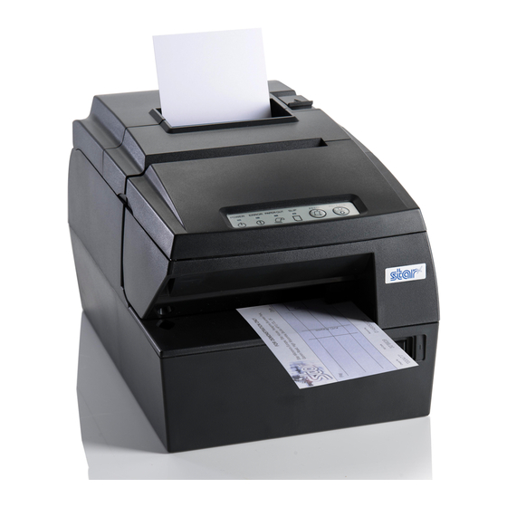
HYBRID PRINTER HSP7000 SERIES Hardware Manual... -
Page 2: Trademark Acknowledgments
HSP7000: Star Micronics Co., Ltd. Notice • All rights reserved. Reproduction of any part of this manual in any form whatsoever, without STAR’s ex- press permission is forbidden. • The contents of this manual are subject to change without notice. -
Page 3: Table Of Contents
TABLE OF CONTENTS 1. Unpacking and Installation ........................1 1-1. Unpacking ............................1 1-2. Choosing a place for the printer ....................2 1-3. Removing the protective materials ....................3 2. Parts Identification and Nomenclature ....................4 3. Setup ................................5 3-1. Connecting the Cable to the PC ....................5 3-2. Connecting the Cable to the Printer .....................7 3-3. Installing the Printer Software ....................11 3-4. Connecting the Optional AC Adapter ..................12 3-5. Turning Power On ........................13 3-6. Switch Cover Installation ......................14 3-7. Connecting to a Peripheral Unit . - Page 4 11-2. RS-232C Interface Model ......................48 11-3. USB/PoweredUSB Interface Model ..................50 11-4. Ethernet Interface Model ......................51 12. Parallel Interface ..........................53 13. RS-232C Serial Interface ........................54 13-1. Interface Specifications ......................54 13-2. RS-232C Connector ........................55 13-3. Cable Connections ........................56 14. USB and Ethernet ..........................57 14-1. USB/PoweredUSB Interface Specifications ................57 14-2. Ethernet Interface Specifications ....................57 15. Peripheral Unit Drive Circuit ......................58 16. Memory Switch Settings ........................60 Please access the following URL http://www.star-m.jp/eng/dl/dl02.htm for the latest revision of the manual.
-
Page 5: Unpacking And Installation
1. Unpacking and Installation 1-1. Unpacking After unpacking the unit, check that all the necessary accessories are included in the package. Switch blind Paper roll Paper guide CD-ROM Interface cover Setup sheets Ribbon cassette Printer Note Note: The ferrite core and fastener provided with your printer depend on your printer configuration. -
Page 6: Choosing A Place For The Printer
1-2. Choosing a place for the printer Before actually unpacking the printer, you should take a few minutes to think about where you plan to use it. Remember the following points when doing this. P Choose a firm, level surface where the printer will not be exposed to vibration. P The power outlet you plan to connect to for power should be nearby and unobstructed. -
Page 7: Removing The Protective Materials
1-3. Removing the protective materials Four protective materials are inserted into the printer to protect components during shipping. Before using the printer, be sure to remove all protective materials as shown in the illustra- tion. (1) Remove the three tapes and pull the two protective sheets. (2) Open the front cover. -
Page 8: Parts Identification And Nomenclature
2. Parts Identification and Nomenclature Rear cover Validation slot Open it to replace the roll paper. Insert paper here. Do not open it during printing. Front cover Open it to replace the ribbon. Do not open it during printing. Cover open lever Push this lever in the direction of the arrow to open the printer cover. -
Page 9: Setup
3. Setup 3-1. Connecting the Cable to the PC 3-1-1. Parallel Interface Cable Connect the parallel interface cable to a parallel port of your PC. 3-1-2. RS-232C Interface Cable Connect the RS-232C interface cable to a RS-232C port of your PC. 3-1-3. - Page 10 3-1-4. PoweredUSB Interface Cable Attach the ferrite core to the PoweredUSB interface cable, and connect the cable to a Pow- eredUSB port of your PC. Recommended Cable: 30729130 POWERED USB CABLE 1X8LNL 1.2M Recommended PCI Card: PCI to 4 Port PoweredUSB Card Maximum 3.5 cm Pull and cut 3-1-5.
-
Page 11: Connecting The Cable To The Printer
3-2. Connecting the Cable to the Printer Note that the interface cable is not provided. Please use a cable that meets specifications. CAUTION Before connecting/disconnecting the interface cable, make sure that power to the printer and all the devices connected to the printer is turned off. Also make sure the power cable plug is disconnected from the AC outlet. - Page 12 3-2-2. RS-232C Interface Cable (1) Make sure the printer is turn off. CAUTION Before connecting/disconnecting the interface ca- RS-232C interface ble, make sure that power to the printer and all the cable devices connected to the printer is turned off. Also make sure the power cable plug is disconnected from the AC outlet.
- Page 13 3-2-4. PoweredUSB Interface Cable (1) Turn the power switch off. (2) If connected to an AC adapter, pull the power cord plug from the outlet and then pull the plug from the power connector on the printer side. CAUTION If connecting a PoweredUSB cable, do not connect the AC adapter because this can cause a malfunction.
- Page 14 3-2-5. Connecting Ethernet Cable (1) Make sure the printer is turned off. (2) Affix the ferrite core onto the ethernet cable as shown in the illustration below. (3) Pass the fastener through the ferrite core. (4) Loop the fastener around the cable and lock it. Use scissors to cut off any excess.
-
Page 15: Installing The Printer Software
3-3. Installing the Printer Software Here is the procedure for installing the printer driver and utility software, which are stored on the supplied CD-ROM. The procedure applies to the Windows operating systems shown below. • Windows 2000 • Windows XP •... -
Page 16: Connecting The Optional Ac Adapter
3-4. Connecting the Optional AC Adapter Note: Before connecting/disconnecting the AC adapter, make sure that power to the printer and all the devices connected to the printer is turned off. Also make sure the power cable plug is disconnected from the AC outlet. (1) Connect the AC adapter to the power cable. -
Page 17: Turning Power On
3-5. Turning Power On Make sure that the Power cord has been connected as described in 3-4. Turn ON the power switch located on the front of the printer. The POWER lamp on the control panel will light up. Power switch CAUTION We recommend that you unplug the printer from the power outlet whenever you do not plan to use it for long periods. -
Page 18: Switch Cover Installation
3-6. Switch Cover Installation It is not necessary to install the switch cover. Only install it if it is necessary for you. By install- ing the switch cover, the following become possible. • Preventing the power switch from being operated by mistake. •... -
Page 19: Connecting To A Peripheral Unit
3-7. Connecting to a Peripheral Unit You can connect a peripheral unit to the printer using a modular plug. See “Modular plug” on page 54 for details about the type of modular plug that is required. Note that this printer does not come with a modular plug or wire, so it is up to you to obtain one that suits your needs. -
Page 20: Attaching The Interface Cover
3-8. Attaching the Interface Cover It is not necessary to attach the interface cover. Only attach it if it is necessary for you. Attach the interface cover as shown in the illustration. (1) Place the printer as shown below. (2) Install the interface cover by aligning the tabs on the interface cover with the grooves in the printer case. -
Page 21: Loading The Ribbon Cartridge And Paper
4. Loading the Ribbon Cartridge and Paper 4-1. Loading the Ribbon Cartridge (1) Turn off power to the printer. (2) Open the front cover by holding the finger grips on both ends of the cover and lifting it up. Important! 1. -
Page 22: Loading The Paper Roll
4-2. Loading the Paper Roll 4-2-1. Using 79.5 mm Width Paper Roll Be sure to use roll paper that matches the printer’s specification. When using a paper roll with an 57.5 mm width, install the paper guide as described on the following page. - Page 23 4-2-2. Using 57.5/75.5 mm Width Paper Roll When using a paper roll with 57.5 or 75.5 mm width, install the supplied paper guide on the printer. To change the effective print width (roll paper width), change the setting at memory switch configuration Utility.
-
Page 24: Loading The Slip Paper Or Validation Paper
4-3. Loading the Slip Paper or Validation Paper Before starting printing, make sure the ribbon cassette is placed in the printer. (See “4-1. Load- ing the Ribbon Cassette” for details.) Insert the paper as follows: (1) Turn the printer power switch ON. (2) Insert the paper as illustrated below. -
Page 25: Scanning Micr Characters
4-4. Scanning MICR Characters Insert a MICR paper as follows: (1) Turn the printer power switch ON. (2) Make sure the ERROR lamp and PAPER OUT lamp are flashing and the SLIP lamp is (3) Place the paper with the MICR characters facing down as illustrated below. As you face the printer, insert the paper straight, while sliding the right end of the MICR paper against the right end of the slip paper slot. - Page 26 Caution Symbol This symbol is placed near the slip print head to indicate that it may be hot. Never touch the slip print head immediately after the printer has been used. Let the print head cool for a few minutes before touching it. This symbol is placed near the thermal print head to indicate that it may be hot.
- Page 27 3 Do not operate the cover open lever while pressing on the printer cover with your hand. 3 Do not pull the cover open lever and open the printer cover when printing is in progress or when the auto cutter is operating. 3 Do not pull out paper while the printer cover is closed.
-
Page 28: Consumable Parts And Ac Adapter
When consumable parts have run out, use those specified in the table below. Note: Access the following URL for the information of the recommended paper. http://www.star-m.jp/eng/dl/dl02.htm Make sure that the AC adapter specified in the table is used. Use of consumable parts or AC adapter which are not specified in the table may result in dam- age to the printer, fire or electric shock. - Page 29 Paper thickness Manufacturer Product name Quality characteristics/Use (µm) Nippon Paper Industries TF50KS-E2D normal type paper 65 (thickness) Kanzaki Specialty Papers P320RB 2 color paper: Red & Black 65 (thickness) Inc. (KSP) P320BB 2 color paper: Blue & Black 65 (thickness) Note: 1) Depending on the type and thickness of the paper, it may be necessary to change the settings for printing darkness.
-
Page 30: Slip Paper
5-2. Slip Paper 5-2-1. Specifications (1) Width: 68 ~ 230 mm (2) Length: 75 ~ 297 mm (3) No. of copies: original + 3 copies (4) Total thickness: 1 sheet 0.09 ~ 0.15 mm (up to A4 portrait) 0.09 ~ 0.20 mm (up to A6 portrait) 4 sheets 0.09 ~ 0.31 mm (5) Copy slippage: 1.5 mm or less per 15 lines (between original and bottom-... -
Page 31: Ac Adapter (Option)
3) The copying performance of the printer is greatly affected by the ambient temperature. Therefore, print under the conditions described below. Number of copies Ambient temperature Original + 3 copies 10 ~ 40°C Original + 1 copy 5 ~ 45°C 5-2-2. -
Page 32: Control Panel And Other Functions
6. Control Panel and Other Functions 6-1. Control Panel 3 PAPER OUT Lamp (Red) 1 POWER Lamp (Green) 4 SLIP Lamp (Green) 2 ERROR Lamp (Red) 5 FEED Button 6 RELEASE Button 1 POWER Lamp (Green) Lights when the printer is online. Describes various errors in combination with other lamps. -
Page 33: Errors
6-2. Errors (1) Recoverable errors Error Description POWER ERROR PAPER SLIP Recovery Conditions Lamp Lamp Lamp Lamp Thermal head high Flashes at Automatically recovered temperature detec- 0.5 second after the thermal head has tion error intervals. cooled. Impact head high Flashes at Automatically recovered temperature detec-... - Page 34 2) Non-recoverable errors Error Description POWER ERROR PAPER SLIP Recovery Conditions Lamp Lamp Lamp Lamp RAM error Flashes at Flashes at Flashes at This is not a recoverable 0.125 sec- 0.125 sec- 0.125 sec- error. ond inter- ond inter- ond inter- vals vals vals...
-
Page 35: Self-Printing
6-3. Self-Printing 6-3-1. Test Printing • Thermal paper roll Place a paper roll on the printer. With the rear cover closed, turn the power switch ON while keeping the FEED button depressed. The printer will run a test print in the following order: version number, DIP switch settings, memory switch settings, etc. - Page 36 6-3-2. Hexadecimal Dump Mode Place the thermal paper roll on the printer. Open the printer cover, then turn the power on while holding the FEED button. When the cover is closed, “*** HEX DUMP PRINTING ***” is printed, and the printer enters the Hexadecimal Dump Mode.
-
Page 37: Adjusting The Near-End Sensor
7. Adjusting the Near-end Sensor Use the following procedure to adjust the near-end sensor so it is compatible with the size of paper roll you are using. (1) Open the rear cover. (2) Determine the diameter of the paper roll you are using and find the required setting in the table below. - Page 38 Adjustment value according to the paper you are using Paper ø12 (A) inner diameter / ø18 (B) outer di- Thickness ameter core roll paper (μm) Detected diameter (C) Remaining paper (mm) length (m) Level 1 Level 2 Level 1 Level 2 Approx.
-
Page 39: Preventing And Clearing Paper Jams
8. Preventing and Clearing Paper Jams 8-1. Preventing Paper Jams 8-1-1. Roll paper While placing a roll paper on the printer, do not pull out the end of the paper diagonally. Also, do not touch the roll paper while it is printing, releasing, or before completing cutting. If you hold or pull the paper with your hands while the paper is being released, it could cause the paper to jam, cut improperly, or place a line break improperly. - Page 40 8-2-2. Slip paper Press the RELEASE button on the control panel in order to auto-release the paper. If the paper cannot be removed by performing an auto-release, open the front cover, push the point A or B on the platen, and remove the paper. Thermal head Caution Symbol This symbol is placed near the slip print head to indicate that it may be hot.
-
Page 41: Releasing A Locked Cutter
8-3. Releasing a Locked Cutter If the auto cutter locks up or fails to cut the paper, follow the steps below. WARNING Since working on the cutter may be dangerous, be sure to turn off the printer first. (1) Turn the printer off and unplug the power cord Cutter cover from the AC outlet. -
Page 42: Maintenance
9. Maintenance Printed characters may become partially unclear due to accumulated paper dust and dirt. To prevent such a problem, paper dust collected in the paper holder and paper transport section and on the surface of the thermal head must be removed periodically. Such cleaning is recommended to be carried out once six month or one million lines. -
Page 43: Cleaning The Paper Holder And The Surrounding Area
9-5. Cleaning the Paper Holder and the Surrounding Area Clean the paper holder of debris, dust, paper particles, glue, etc. that may have accumulated. Rubber roller Thermal head – 39 –... -
Page 44: Specifications
10. Specifications 10-1. General Specifications 10-1-1. Thermal Printer (1) Printing method Direct line thermal printing (thermal type) (2) Print speed Max. 2000 dots/sec. (250 mm/sec.) (normal type paper) (3) Dot density 203 dpi: 8 dots/mm (0.125 mm/dot) (4) Printing width Max. 72 mm (5) Number of print columns Max. -
Page 45: Auto Cutter Specifications
(10) Paper feed speed: max. 141 mm/sec. (11) Ink ribbon: Type Cartridge cassette Color Black Material Nylon #40 denier (12) Paper specifications: For details, see “5. Paper and AC Adapter”, “5.2 Slip Paper Specifications”. 10-2. Auto Cutter Specifications (1) Cutting Modes Partial cut (leaves one uncut portion in center of paper) (2) Cutting Duty Min. -
Page 46: Interface Specifications
10-5. Interface Specifications Selectable interface card type • Parallel: Amphenol 36 pin Conforming to IEEE 1284 (compatibility mode, nibble mode) • Serial RS-232C: D-SUB25 pin • USB: Type B • Ethernet: RJ-45 • PoweredUSB: FCI 69913-104LF (1x8 right-angle type) Type B connector: DUSB-BRA42-T11 (D2)-FA (manufacturer: DDK) Pin number Signal name... -
Page 47: Electrical Characteristics (Ac Adapter)
10-6. Electrical Characteristics (AC adapter) (1) Input: 100 to 240 V AC, 50/60 Hz (2) Output: DC 24 V ± 10% (3) Current Consumption (DC 24 V at room temperature) Standby: Approx. 0.1 A ASCII printing: Approx. average 2.2 A 100% print duty: Approx. -
Page 48: Environmental Requirements
10-7. Environmental Requirements (1) Operating Temperature 5°C to 45°C Humidity 10% to 90% RH (without condensation) (%RH) 34°C90% RH 40°C65% RH 45°C50% RH Operating environment range Temperature (°C) Operating temperature and humidity range (2) Transport/storage (except for paper) Temperature -20°C to 60°C Humidity 10% to 90% RH (without condensation) * However, the combination of 40°C and 90% RH (no condensation) is considered the worst... -
Page 49: Reliability Specifications
10-8. Reliability Specifications 10-8-1. Thermal Printer (1) Life Mechanical: 20 million lines Head: 150 km, 150 million dots (for monochrome printing) <Conditions> Average printing ratio: 12.5% Recommended thermal paper: 65 µm (2) MCBF: 60 million lines The Mean Cycle Between Failure (MCBF) is defined to be the overall failure cycle, which includes random or wear failures that occur until the printer reaches its mechanical life of 20 million lines. -
Page 50: Dip Switch Setting
11. Dip Switch Setting Two DIP switches are provided at the bottom of the printer, and can be set as given in the table below. Be sure to set the power switch to off before changing the settings. It is recommended to use a pointed item like a pen or flat‑blade driver screw to change the settings. -
Page 51: Parallel Interface Model
No. 1 2 3 4 DIP-SW 1 DIP-SW 2 DIP-SW 1 Switch Function Command emulation (Star Line Mode) Always ON Should not be changed (Should be set to on) Should not be changed (Should be set to on) Sensor adjustment Invalid... -
Page 52: Rs-232C Interface Model
11-2. RS-232C Interface Model No. 1 2 3 4 5 6 7 8 9 10 No. 1 2 3 4 DIP-SW 1 DIP-SW 2 DIP-SW 1 Switch Function Command emulation Always ON Should not be changed (Should be set to on) Should not be changed (Should be set to on) Sensor adjustment Invalid... - Page 53 The following is the procedure for changing the settings on DIP switch No. 3. (1) Turn off the printer and all components connected to it. (2) Remove the 2 screws. (3) Remove the serial interface board unit. (4) Change the setting of the DIP switches. (5) Replace the serial interface board unit.
-
Page 54: Usb/Poweredusb Interface Model
11-3. USB/PoweredUSB Interface Model No. 1 2 3 4 5 6 7 8 9 10 No. 1 2 3 4 DIP-SW 1 DIP-SW 2 DIP-SW 1 Switch Function Command emulation (Ster Line mode) Always ON Should not be changed (Should be set to on) Should not be changed (Should be set to on) Sensor adjustment Invalid... -
Page 55: Ethernet Interface Model
11-4. Ethernet Interface Model No. 1 2 3 4 5 6 7 8 9 10 No. 1 2 3 4 DIP-SW 1 DIP-SW 2 DIP-SW 1 Switch Function Command emulation (Ster Line mode) Always ON Should not be changed (Should be set to on) Should not be changed (Should be set to on) Sensor adjustment Invalid... -
Page 56: Initializing Settings
Initializing Settings ■ Set the push switch as described below to initialize the setting information. Push the switch for one to five seconds while running under normal operating mode. The green and red LEDs will flash with a regular pattern. After that, push the switch once again in that state to turn OFF both of the red and green LEDs. -
Page 57: Parallel Interface
12. Parallel Interface The two-way parallel interface is compatible with the IEEE1284 compatibility mode and nibble mode. Contact your dealer for details. Table of Connection Signals for Each Mode Compatibility Mode Nibble Mode Pin No. Direction Signal Name Signal Name nStrobe Host Clock In/Out... -
Page 58: Rs-232C Serial Interface
13. RS-232C Serial Interface 13-1. Interface Specifications (1) Data transmission method: Asynchronous serial interface (2) Baud rate: Selectable from 4800, 9600, 19200, 38400 bps (Refer to “11. DIP Switch Setting”.) (3) Word length Start bit: 1 bit Data bit: 7 or 8 bits (selectable.) Parity bit: Odd, even or none (selectable.) Stop bit: 1 bit length (4) Signal polarity... -
Page 59: Rs-232C Connector
13-2. RS-232C Connector Pin No. Signal name Direction Function F-GND — Frame ground Transmission data Receive data Always SPACE Not used. Not used. S-GND — Signal ground 8~19 Not used. A) DTR/DSR communication mode Indicates whether data receive from host is enabled or disabled. -
Page 60: Cable Connections
13-3. Cable Connections The followings are a recommended interface cable connections. Printer side Host side 25 pin 9 pin INIT Note: Use shielded wire less than 3 m in length. – 56 –... -
Page 61: Usb And Ethernet
14. USB and Ethernet 14-1. USB/PoweredUSB Interface Specifications (1) General Specification: Conforms to USB 2.0 Specifications (2) Communication Speed: USB Full Speed Mode (12 Mbps) (3) Communication Method: USB Bulk Transmission Mode (4) Power Specifications: USB Self‑power Function (5) Connector: USB: USB Up-Stream Port Connector (USB Type-B) PoweredUSB: 1 ×... -
Page 62: Peripheral Unit Drive Circuit
15. Peripheral Unit Drive Circuit Peripheral unit drive circuit connector only connects to peripheral units such as cash drawers, etc. Do not connect it to a telephone. Use cables which meet the following specifications. Peripheral Drive Connector Modular plug Signal Function Modular plug: MOLEX 90075-0007, name... - Page 63 Reference 2SD 1866 Circuit Configuration R3 = 3.5 kΩ Drive Output: 24 V, Max. 1.0 A R4 = 300 Ω TR1, TR2: Transistor 2SD 1866 or equiva- lent R1=10 kW R2=33 kW Notes: 1) Peripheral units 1 and 2 cannot be driven simultaneously. To drive them continuously, set the duty cycle ratio to 20% or less.
-
Page 64: Memory Switch Settings
16. Memory Switch Settings Each memory switch is stored in EEPROM. For details on the functions and settings of memory switches, please consult the dealer. The table below shows the factory settings for the memory switches. Memory Switch Hexadecimal Code 0000 0000 0000... - Page 65 424-0066 Japan Tel: (int+1)-732-623-5555, Fax: (int+1)-732-623-5590 Tel: (int+81)-54-347-0112 Fax: (int+81)-54-347-0709 STAR MICRONICS EUROPE LTD. Star House, Peregrine Business Park, Gomm Road, Please access the following URL High Wycombe, Bucks, HP13 7DL, U.K. http://www.star-m.jp/eng/dl/dl02.htm Tel: (int+44)-1494-471111, Fax: (int+44)-1494-473333 for the latest revision of the manual.
Need help?
Do you have a question about the HSP7000 SERIES and is the answer not in the manual?
Questions and answers