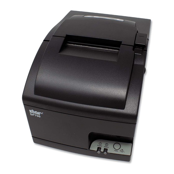
Star SP742 Series Hardware Manual
Dot printer
Hide thumbs
Also See for SP742 Series:
- Specifications (2 pages) ,
- Hardware manual (40 pages) ,
- Hardware manual (56 pages)
Table of Contents
Advertisement
Advertisement
Table of Contents


Need help?
Do you have a question about the SP742 Series and is the answer not in the manual?
Questions and answers
We have a sp742 printer and it now only prints in red. I have changed the ink and still red.
The Star SP742 printer may only print in red after changing the ink if a black/red ribbon (RC700BR) is installed and the ribbon is not correctly positioned. If the ribbon is misaligned or stuck in the red section, the printer will only use the red ink. Adjust or reinstall the ribbon to ensure proper positioning between the black and red sections.
This answer is automatically generated